|
|
|
|
|

|
|
Germany WWII Abwehr OG
The complete radio set (transmitter and receiver) is housed inside
a medium-sized tin case, much like a biscuit tin of the era, which is why
the set is often referred to as Keksdose (biscuit tin), just like its
3-piece predecessor, the SE 108/10. 2
The set is powered by an external battery pack
that provides 1.2V (LT),
90V and 270V (HT), but can also be used with an (optional)
power supply unit (PSU)
that is coupled directly to the power socket
at the rear.
The 3 Watt crystal-operated transmitter can have up to
two fixed channels
in addition to a flexible one with a plug-in crystal.
|
|
|
The receiver is freely adjustable over the entire frequency range, but
has a somewhat limited span (3.2 to 6.5 MHz) compared the transmitter
(3.3 - 7.5 MHz). 3 The transmitter is suitable for CW only and was used
for sending messages in morse code,
using the built-in removable morse key.
Note that all text on the top panel and the knobs is in English.
This was done to hide the actual (German) identity of the equipment,
and to assist any non-German-speaking Abwehr operators.
Each radio came with a 2-page instruction sheet
that was available in multiple languages. The sheet carried the serial
number of the radio and was accompanied by a calibration sheet that converts
the linear scale of the receiver into frequencies. The sheet also contains
the (hand-written) frequency ranges of transmitter and receiver,
the frequencies of the (optional) internal crystals
and the required length of the antenna wires.
See for example the sheet for #580
[A].
Approximately 500 units were built during WWII [5], most of which
fell into the hands of radio amateurs once the war was over.
Shortly afterwards however, in 1946, the Americans established a
new German intelligence agency that became known as
Organisation Gehlen (OG).
The new OG subsequently recruited old Abwehr personnel, most of
which were radio amateurs, and tried to re-activate the wartime
agents in the Eastern Block. As the OG urgently needed radio equipment,
they tried to buy back as many SE 109/3 (and other) sets as possible,
which is one of the reasons why Abwehr spy radio sets
are so rare [5].
The SE-109/3 was succeeded in 1953 by the 12WG.
|
 |
-
OKW = Oberkommando der Wehrmacht (Supreme Command of the Armed
Forces) in Nazi Germany during the Second World War.
Aussenstelle = Outpost.
-
In Louis Meulstee's book Wireless for the Warrior Volume 4, the SE-108/10
is referred to as SE-100/11 [1]. Both names are believed to be correct,
and are believed to be related to manufacturing changes only.
-
Note that different frequency ranges were used for specific missions [1].
|
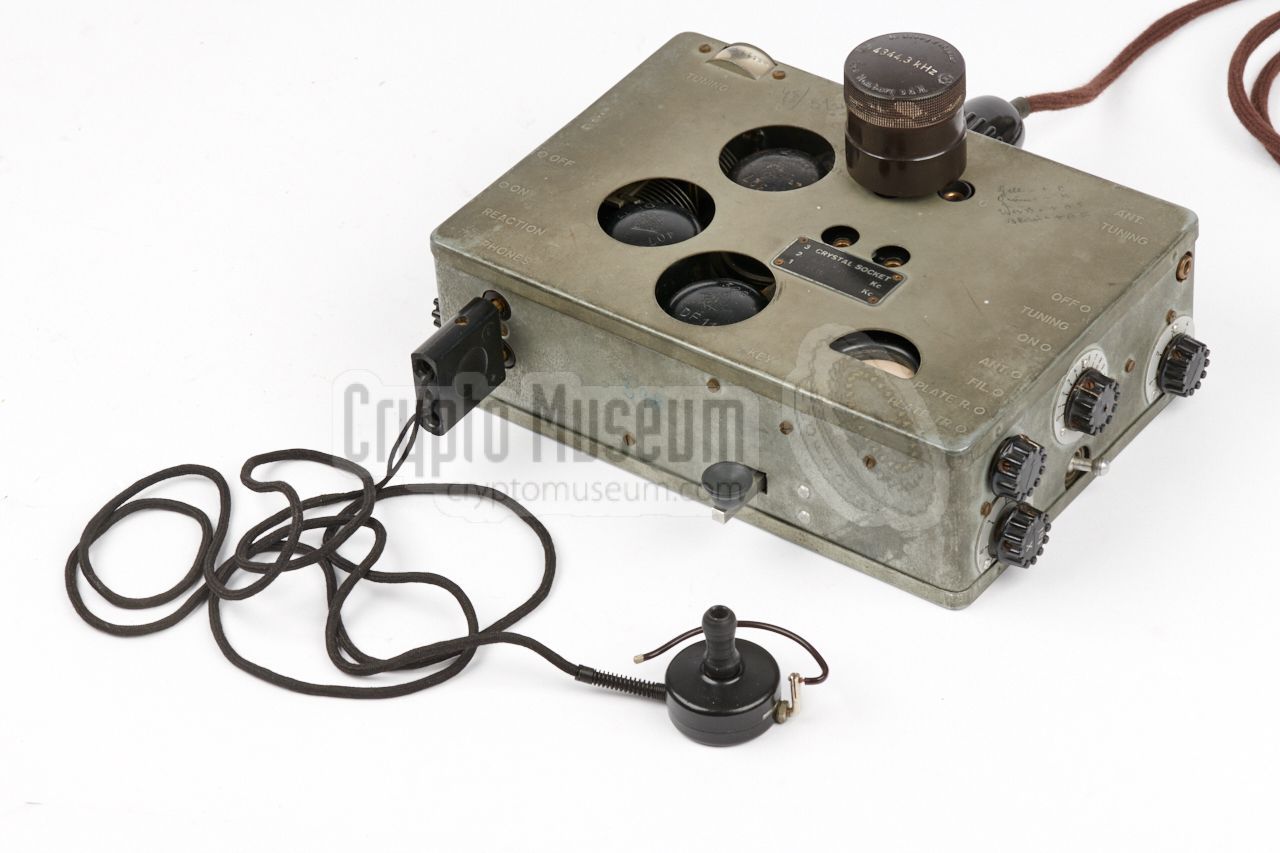
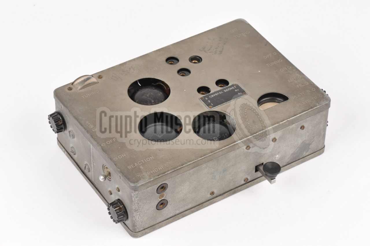
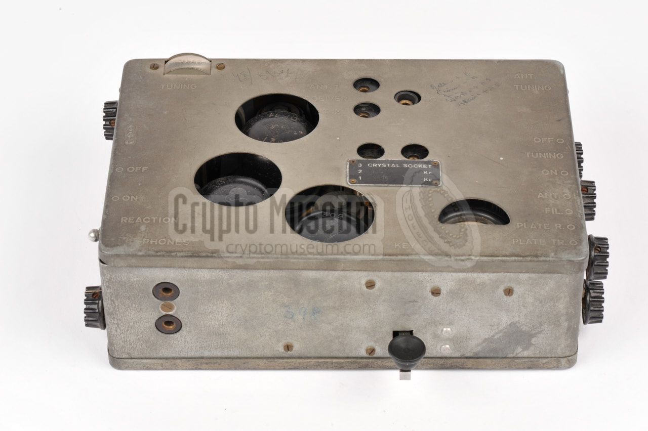
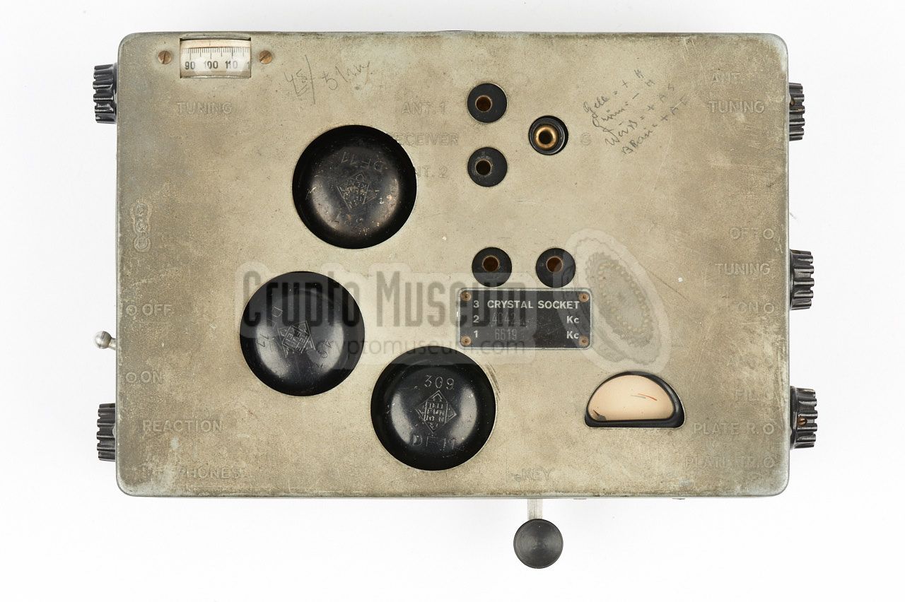
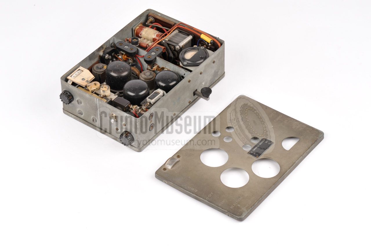
The SE 109/3 measures 20 x 14 x 6 cm and weighs just 1.7 kg.
It has controls and connections at all sides, except for the bottom.
The case consists of a rectangular tin frame with rounded corners and
easily removable top and bottom panels.
The left 2/3 is occupied by the receiver,
whilst the remaining 1/3 houses the transmitter. The top panel has three
large holes through which the black metal DF11 valves of the receiver
are visible. The holes provide their cooling.
Antenna and counterpoise for the receiver should be
connected to the banana sockets at the top panel.
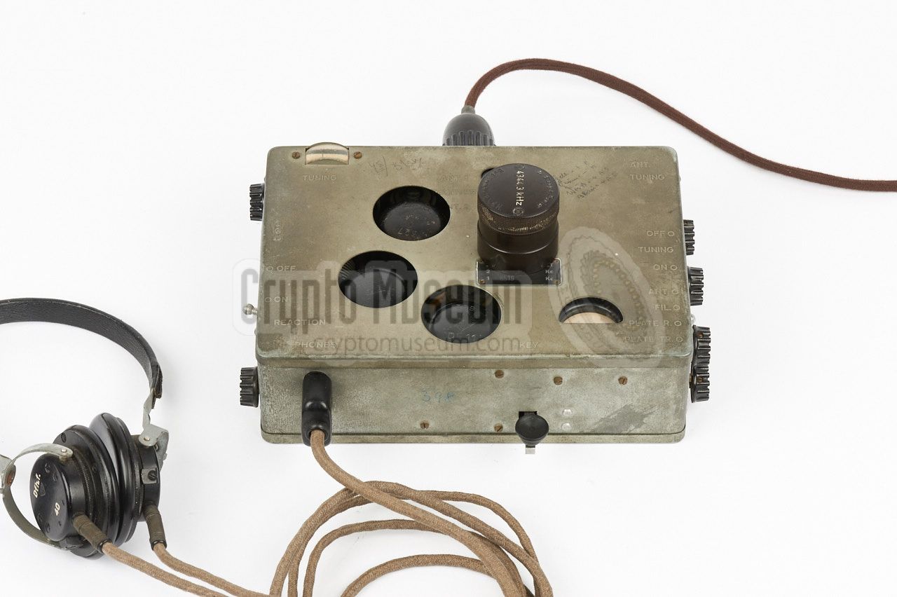
A dynamic 4000Ω earpiece,
or a pair of 2 x 2000Ω headphones should be connected
to the banana sockets at the left of the front panel.
A suitable Rosinski Kleinhörer was supplied.
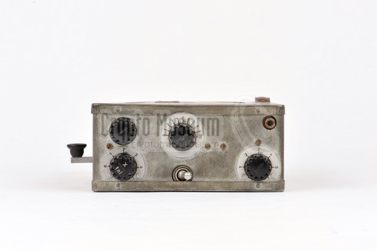
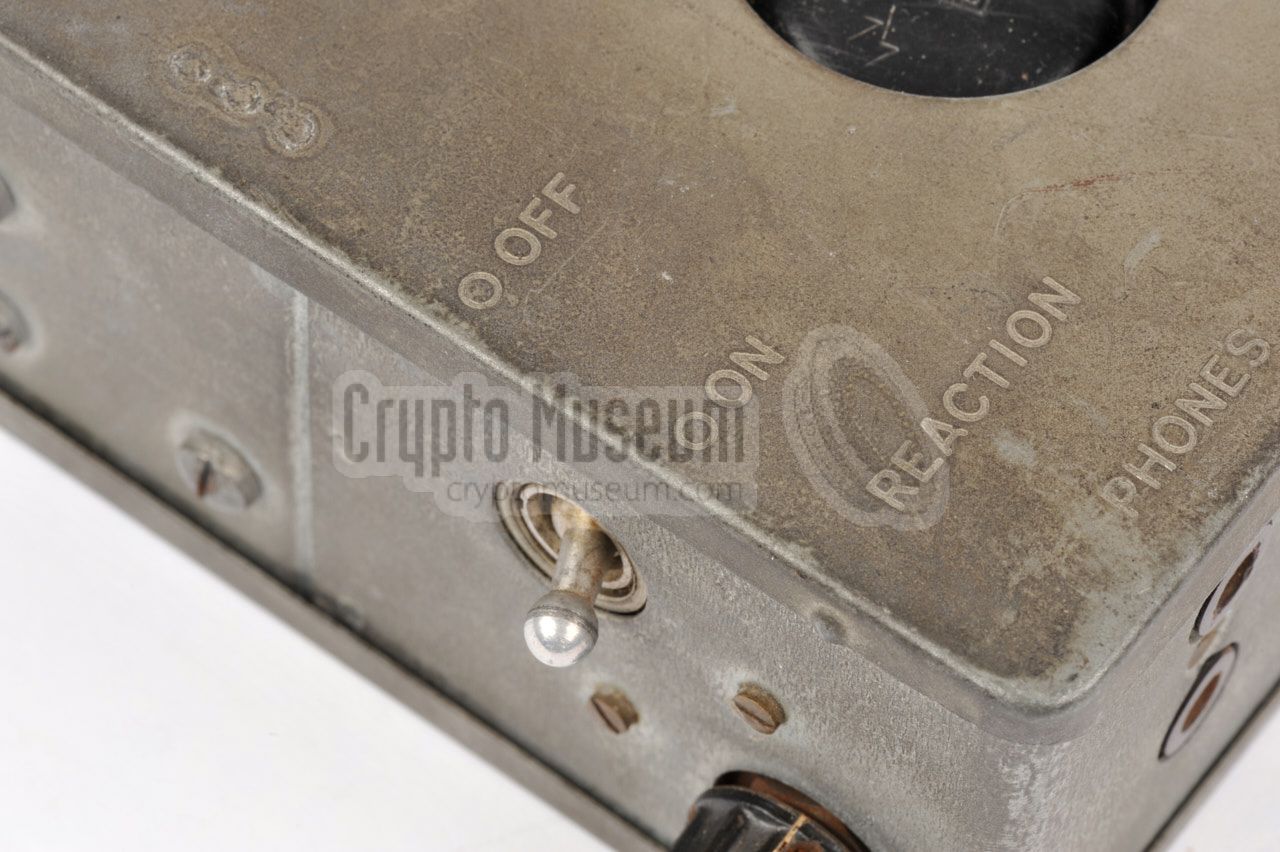
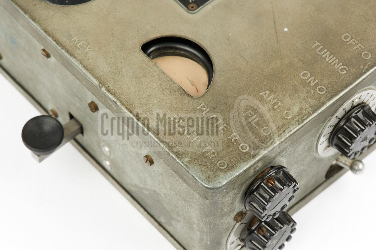
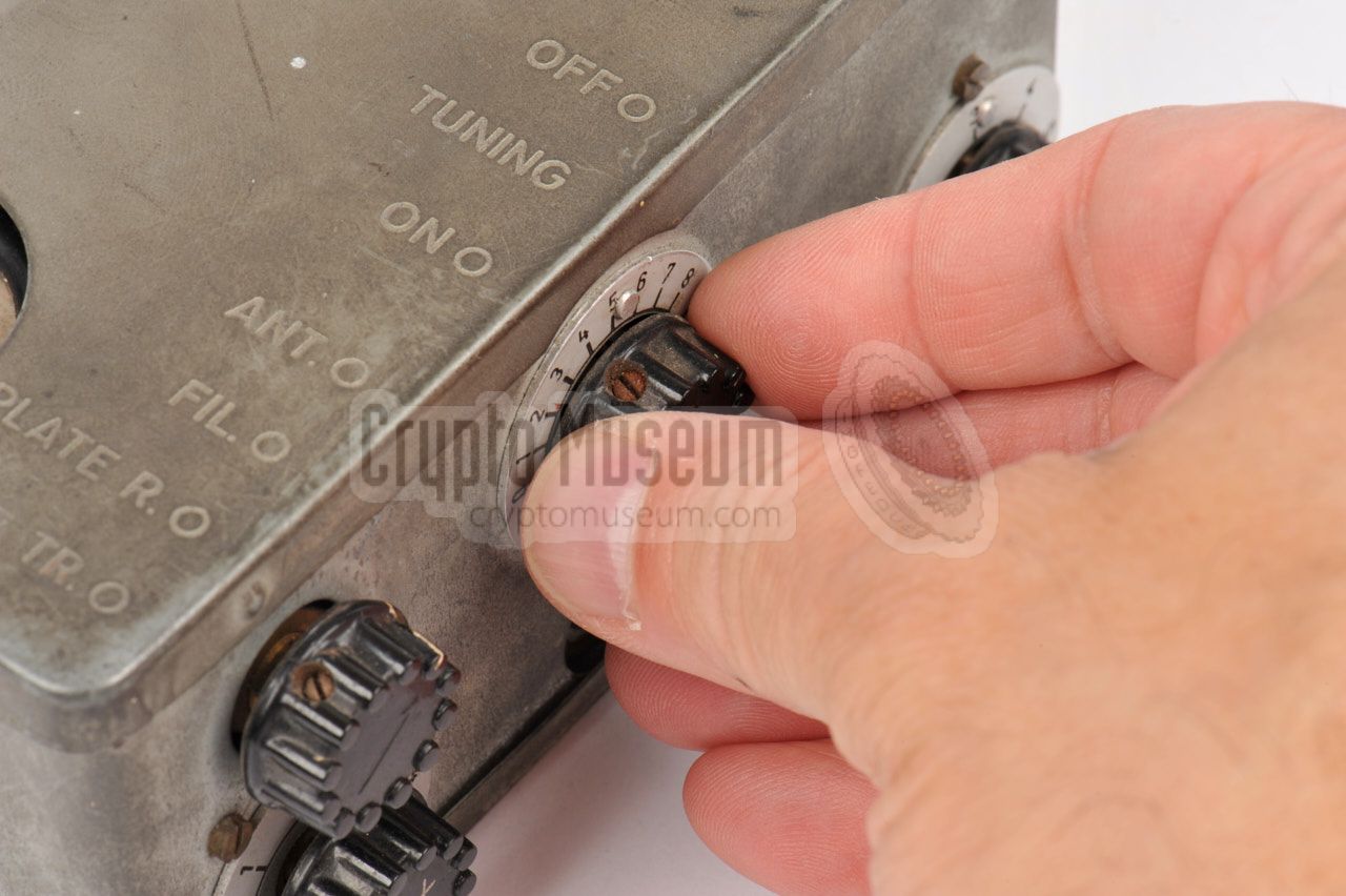
All controls of the receiver are located at the left side panel.
The ON/OFF switch is used to enable the LT voltage for the filaments.
The knob closest to the rear, is used for adjusting the receive
frequency between 3.2 and 6.5 MHz. 1 When tuning, the current
setting can be read from the linear index scale at the top panel.
Reaction is controlled with
the knob closest to the front.
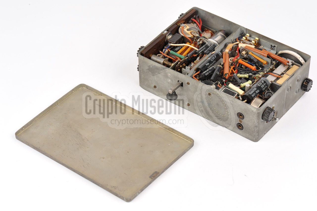
All controls of the transmitter are located at the right side
panel, where also a suitable transmit antenna should be connected.
The transmitter can have up to two built-in crystals
with a fixed frequency, selectable with a
rotary selector at the right.
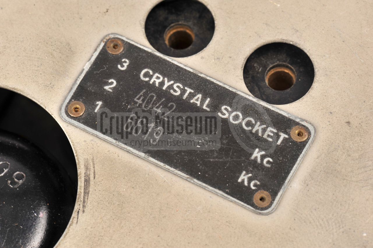
In addition, an external crystal may be inserted in the crystal
socket at the center of the top panel
(set the Xtal selector to position 3).
The ON/OFF switch is used to
enable the LT voltage to the filaments of the DLL22T valve.
The transmitter is only suitable for CW transmissions (morse),
using the internal morse key at the front. When in transit,
the morse key can be removed and
stored inside the device.
There is no connection for an external morse key.
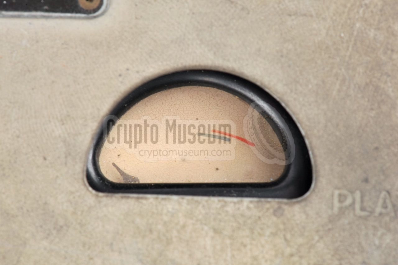
When transmitting, the antenna-coupling knob and the oscillator
tuning should be adjust for maximum output, using the
indicator
at the top right.
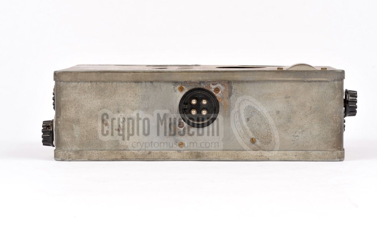
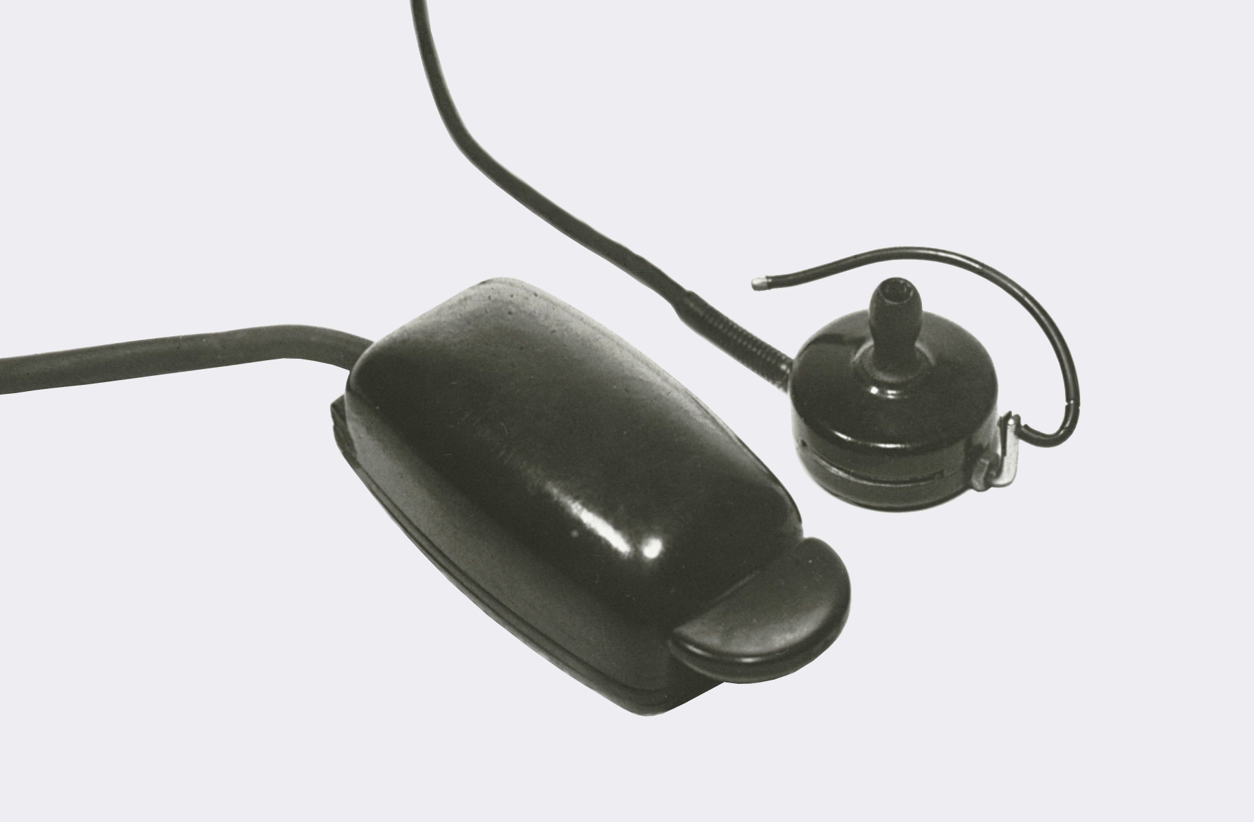
The SE-109/3 is powered by external batteries, or an
external Power Supply Unit (PSU),
that should be connected to the 4-pin socket
at the rear.
The image above shows the position of the power socket,
which is a so-called break-connector (German: Brechkupplung) that
was commonly used by the German Luftwaffe (Air Force).
The radio needs three voltages: 1.2V, 90V and 270V.
|
|
-
Note that different frequency ranges were used for specific missions [1].
|
|
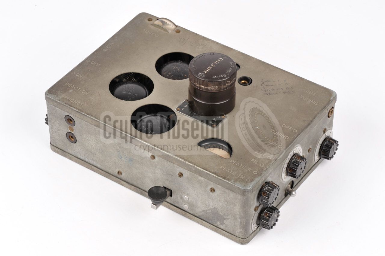
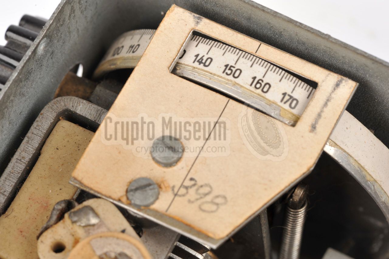
Most SE-109/3 radios have a serial number that consists of 3 or 6 digits.
This serial number is somehow 'encrypted', so that it is not possible to
determine from the surviving samples how many devices were manufactured.
However, from talks with the person who was responsible for the tin
enclosures,
Rudolf Staritz determined that approx. 500 units were made
[5].
|
If the serial number is present, it is usually written on the receiver's
tuning scale with a pencil, as shown in the example on the right.
The serial number of this device is 398.
Furthermore, the serial number may also be written on the front panel
of the device (or in fact anywhere else on the radio's body)
either with a black or a blue pencil. In our case, the serial number is
also present on the front panel.
|
|
|
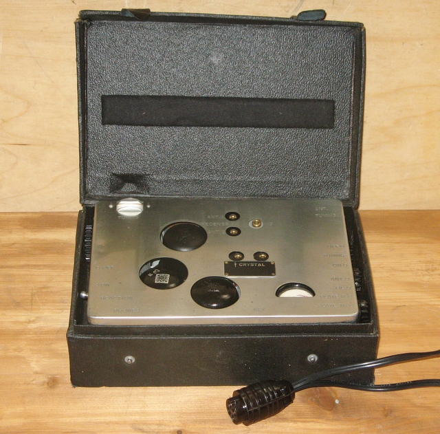
When in transit, the SE-109/3 was usually stored in a small plywood
case that was covered with black faux leather. It had two leather straps
to keep it closed. A similar box was available for the
battery pack that housed the 1.2V battery for the
filaments and three 90V anode batteries.
The image on the right shows an SE 109/3 outside its storage case.
The battery case has extra space for the cables, ear piece and crystals [11].
In this case, the battery box has been converted into a mains
power supply unit (PSU).
|
|
|
The image on the right shows a near-mint SE 109/3 radio inside an original
storage case. Note the small cut-out in the top lid that accomodates the
lens of the receiver's tuning scale. Als note that the case has no room for
the cables, earphone, crystals or any other accessories.
Photograph kindly supplied by anonymous collector. Click the image for a closer view.
|
|
|
|
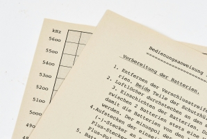
The SE 109/3 was usually supplied with a four page instruction guide.
On the first two pages, it is explained how the radio and its batteries
are to be connected and operated. The frequency range of the radio and
the frequencies of the enclosed crystals are hand-written on the second
page.
|
The third page shows the position of
the various controls and connections on the radio's body, whilst
the last page shows a personalised curve that translates the receiver's
linear tuning scale (0-180) to actual frequencies (2900-5600 kHz).
A copy of an original SE 109/3 instruction sheet is available for
download below [A]. As these sheets were probably individually
hand-typed at the time, or perhaps three simultaneously by means of carbon
paper, the text contains many typographical and lingual mistakes.
It is very likely that most, if not all, sheets are unique.
|
|
|
As the original (scanned) instruction guide is barely readable, we have
made a reproduction of it, in which we have also corrected some obvious
errors and spelling mistakes. The editable fields and the frequency
chart have been left blank, so that it can be tailored for a specific
radio.
➤ Reproduction of the original instructions
|
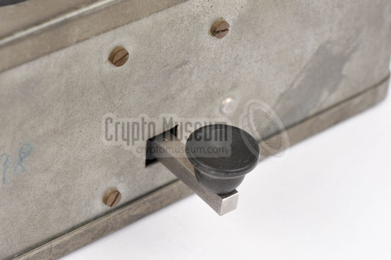
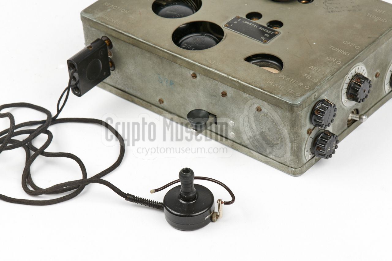
The SE-109/3 has a built-in key that is located at the front side of the
radio at a convenient hight. The arm with the black bakelite knob is
removable
and can be stored inside the device,
in a small brass bracket that is attached to the panel between
the transmitter and the receiver.
The radio was originally supplied with two arms for the morse key:
one inserted at the front,
and a spare one inside the radio [A]. In most cases however,
one of them has been lost over time.
Note that, unlike on earlier devices, there is no connection or socket for an
external morse key.
|
|
|
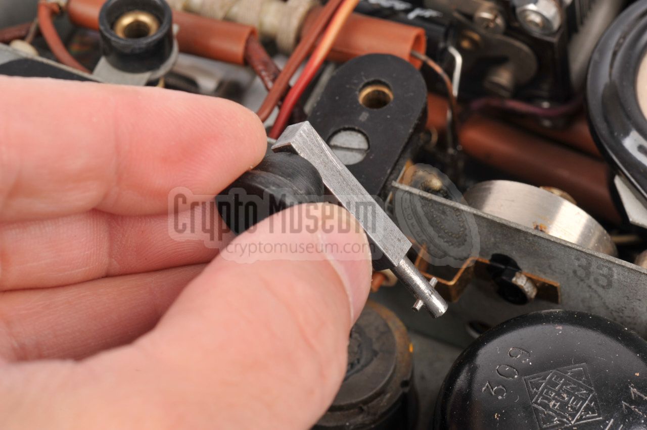
In case the morse key of your SE-109 radio is missing, the drawing below should
provide enough information to create a suitable replacement. The arm
consists of a square shaft with a circular Ø 3 mm stub at the end that is
inserted into the radio. A hardened Ø 1 mm pin keeps it straight up.
The arm is made of steel, whilst the knob is made of black bakelite.
➤ Download as PDF file
|
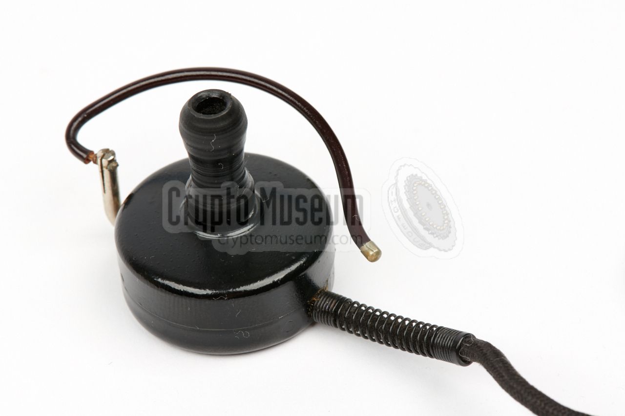
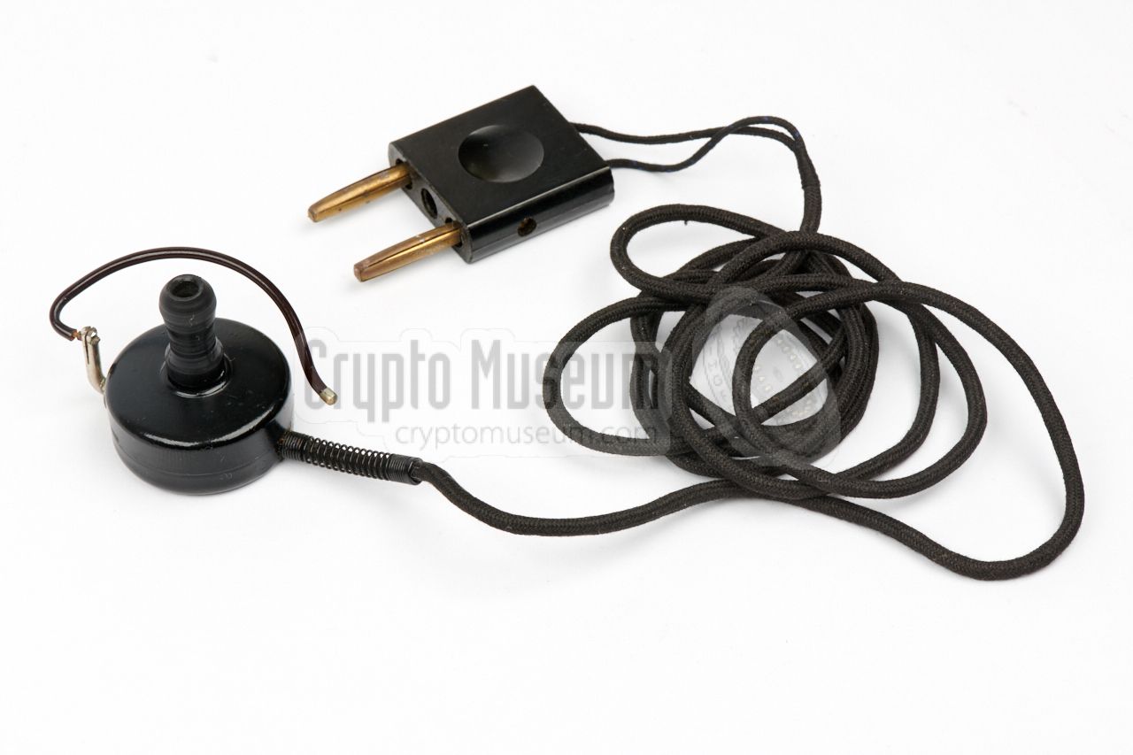
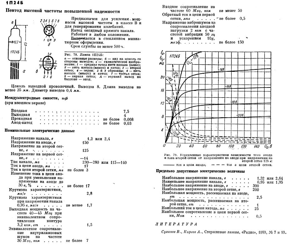
Although the receiver is suitable for connection of virtually any
type of high-impedance headphones, it was originally supplied with a small
2000 Ω dynamic earphone, known as Ohrhörer or Kleinhörer, supplied
by K. Rosinski in Berlin.
This earphone has a diameter of 34 mm and weighs just 35 grams.
To accomodate the user, it was supplied with three different olive-shaped
in-ear pieces. The Rosinski Kleinhörer was available from 1937 onwards.
The one shown in the image on the right was made during WWII by
Ideal (later: Blaupunkt).
|
|
|
Alternatively, the SE 109/3 could also be used with a
common pair of high-impedance headphones,
that were also used with Wehrmacht equipment of the era.
The headphones shown here are the Dfh.f. 40.
The headset consists of two speakers with an impedance of 2000 Ω each.
Note that the headphones are connected in series with the anode of the
DF11 AF amplifier valve, and carry a +90V DC voltage.
This means that the wires should be properly isolated.
|
|
|
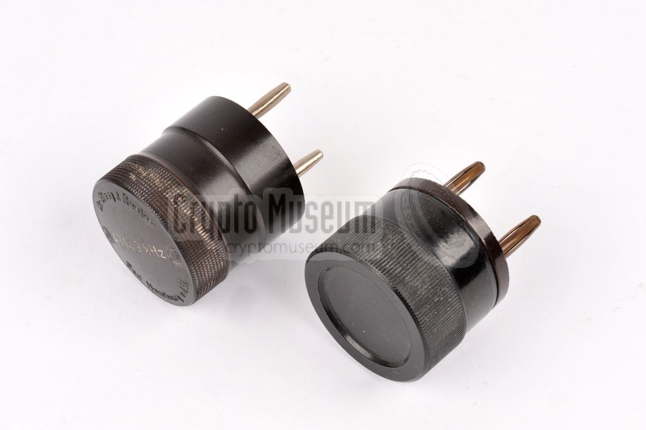
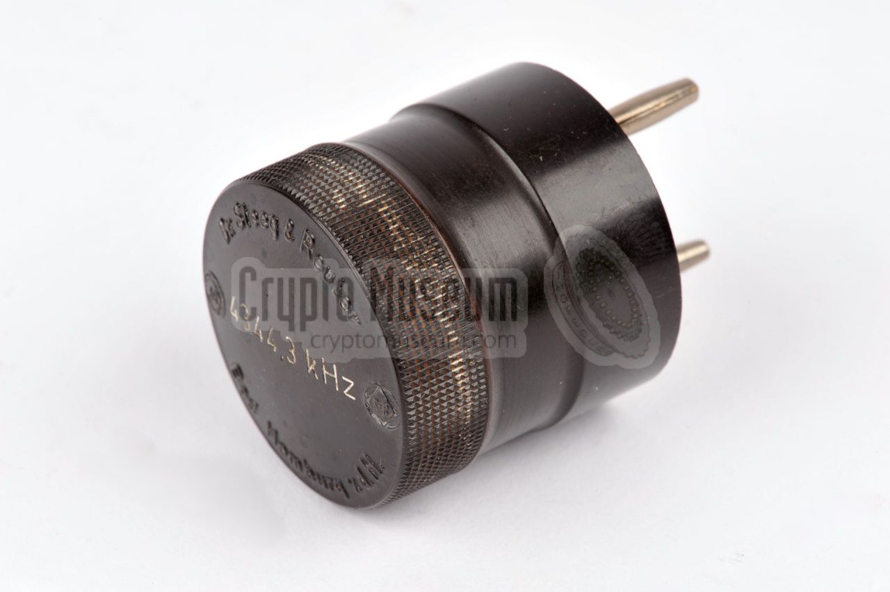
The transmitter is crystal operated in the range 3.3 - 7.5 MHz. 1
A suitable crystal with a
pin distance of 19 mm 2
should be installed in the crystal socket at the center of the top surface.
Note that for this, the crystal selector at the right side (marked Xtal),
should be set to position 3.
Although virtually any type of quartz crystal with the appropriate
base can be used, the radio set was commonly supplied with cylindrical
plug-in crystals, such as the ones shown in the image on the right.
The left one is for 4,3443 MHz and is made by Steeg und Reuter 3
in Bad Homburg.
➤ More about crystal shapes
|
|
|
-
Alternative frequency ranges are known to have existed.
-
The socket's pin distance is 19 mm, but crystals with a pin distance
of 20 mm will often fit.
-
Dr. Steeg & Reuter is now part of Jenoptik AG.
|
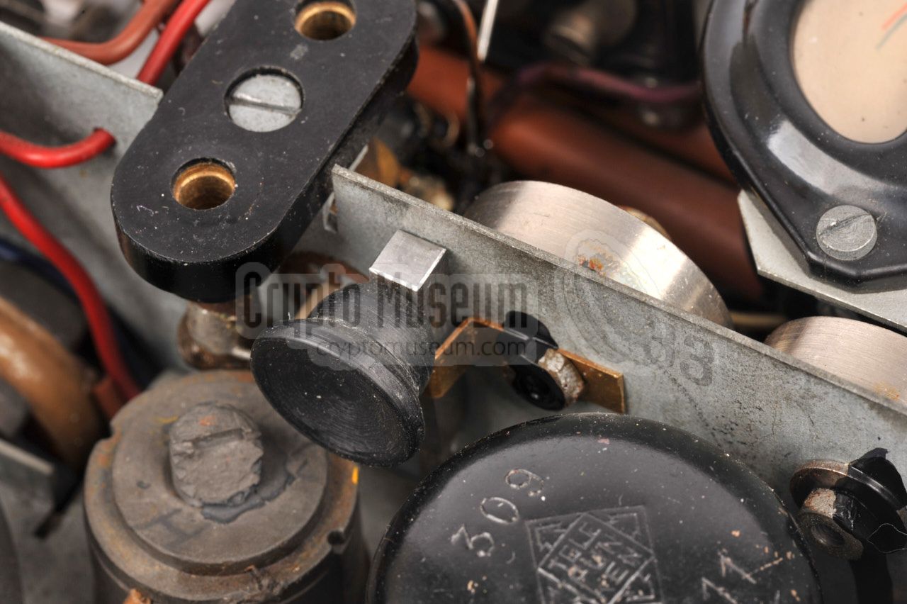
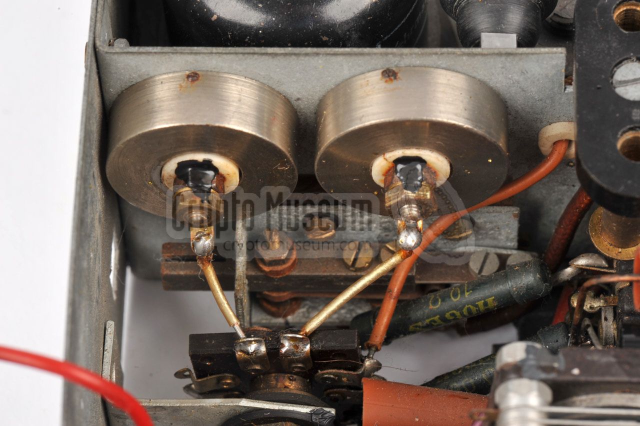
In additon to the external crystal that is installed on top of the device,
as described above, it was also possible to (optionally) install two
internal crystals for fixed channels. These crystals were permanently
installed and wired, and could not be swapped easily. They were mounted to
the panel between the transmitter and the receiver.
The image on the right shows the two internal crystals.
When present, they are available at settings 1 and 2 of the
crystal selector 1
(Xtal).
Furthermore, their frequencies were engraved in the
black plate below the
external crystal socket.
|
|
|
-
Note that the Xtal selector has four usable settings, but that only
positions 1, 2 and 3 are used. Position 4 is unwired. Also note that
positions 5-8 are mapped to positions 1-4.
➤ More...
|
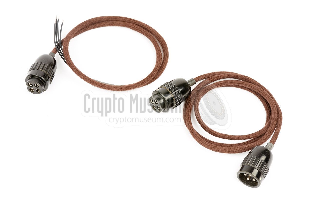
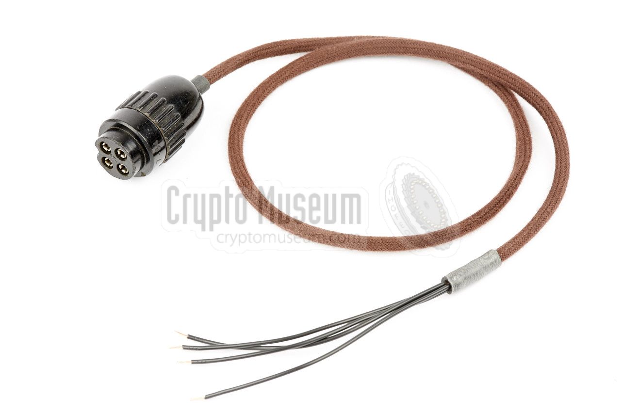
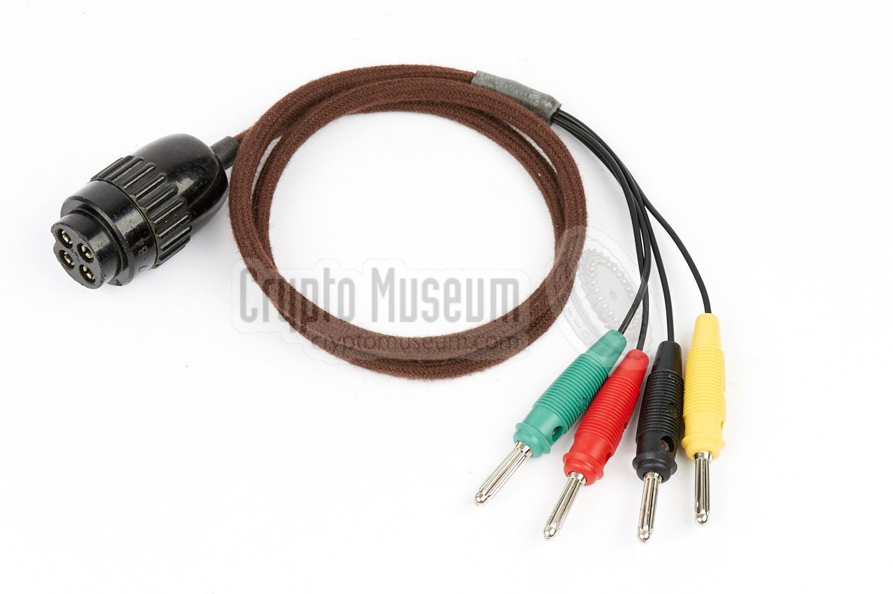
The cable with the loose
ends should normally have four 3.5 mm screw-in plugs that fitted the
batteries of the era. We have temporarily
fitted 4 mm banana plugs
in order to test the device.
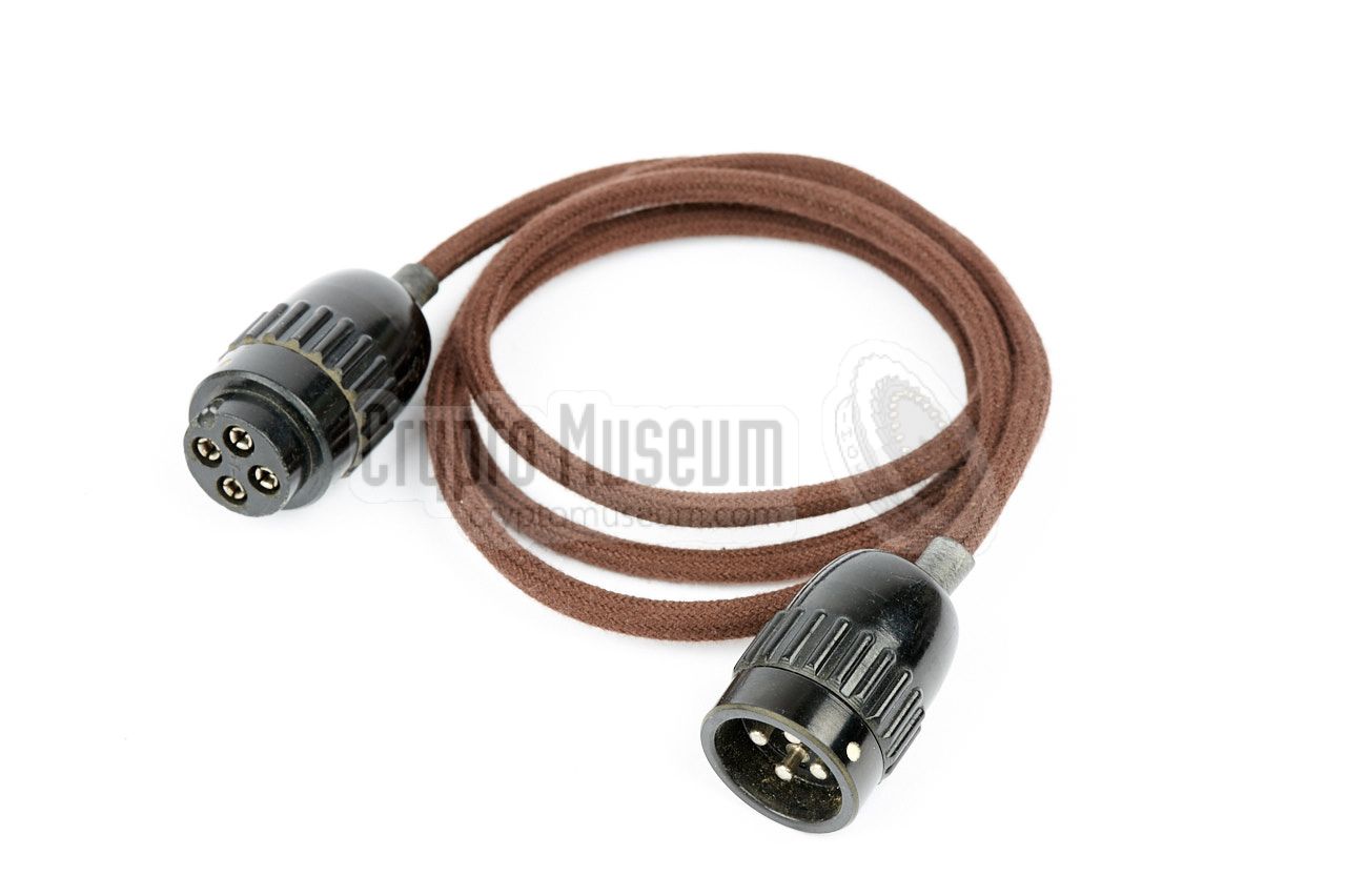
The other one is an extension cable that has a male plug at one end
and a female plug at the other end. This cable was used for connection
between the radio set and the battery case or for connection of
an external power supply unit.
The plugs that are used here, are so-called break-connectors
(German: Brechkupplung) that were commonly
used by the Luftwaffe (Air Force).
|
|
|
There are two known battery arrangements that were used with the
SE 109/3. The first one (A) is shown below. It is similar to the
battery arrangement of the SE 98/3,
with the exception that the LT voltage is 1.2V rather than 3V.
The HT voltages are made with three 90V anode batteries that are
connected in series, with a tap after the first battery.
This produces +90V and +120V HT.
There was also an arrangment (B) that consisted of two external
battery cases, one for the LT voltage and one for the HT voltages.
The LT battery case housed five large heavy-duty 1.2V dry batteries
that were connected in parallel. The HT battery case accomodated
five LS-Zwerg batteries of 60V each, that were connected in series,
with a tap after the second battery. Each of the battery cases had
a male and a female socket that was fully wired, so that they could
be connected to the radio in any order using two of the
male/female extension cables shown above.
Note that in this arrangement the HT voltages are somewhat higher
than with arrangement (A):
+120V for the receiver and +300V for the transmitter. The higher
voltage for the receiver should not cause any trouble. For the
transmitter it means that the DLL22T valve was operated outside
its specifications. It would produce more power, but would also
be more vulnerable to antenna mismatches.
This is probably one of the reasons why very few DLL22T valves
have survived.
The diagram above shows how in the case of arrangement (B)
the battery cases were cascaded. The LT and HT cases could be
swapped as they were both fully wired. Furthermore, the battery
cases could be connected directly to the socket of the radio
without any cables being used, as the connectors are at the same
height. Move the mouse over the image to see the alternative
setup.
|
The radio can also be powered by an optional external power
supply unit (PSU) that is housed in a small tin box, similar to
the SE-108/10 PSU.
The PSU can be placed behind the radio set and is
plugged straight into
the break-connector at the rear. Alternatively,
it can be connected via an optional
extension cable.
Note that the PSU of the earlier
SE-108/10 radio can not
be used, as it has a different pinout.
|
|
|
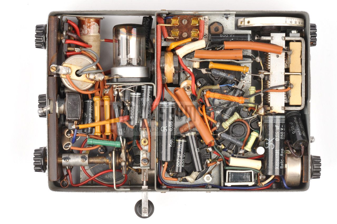
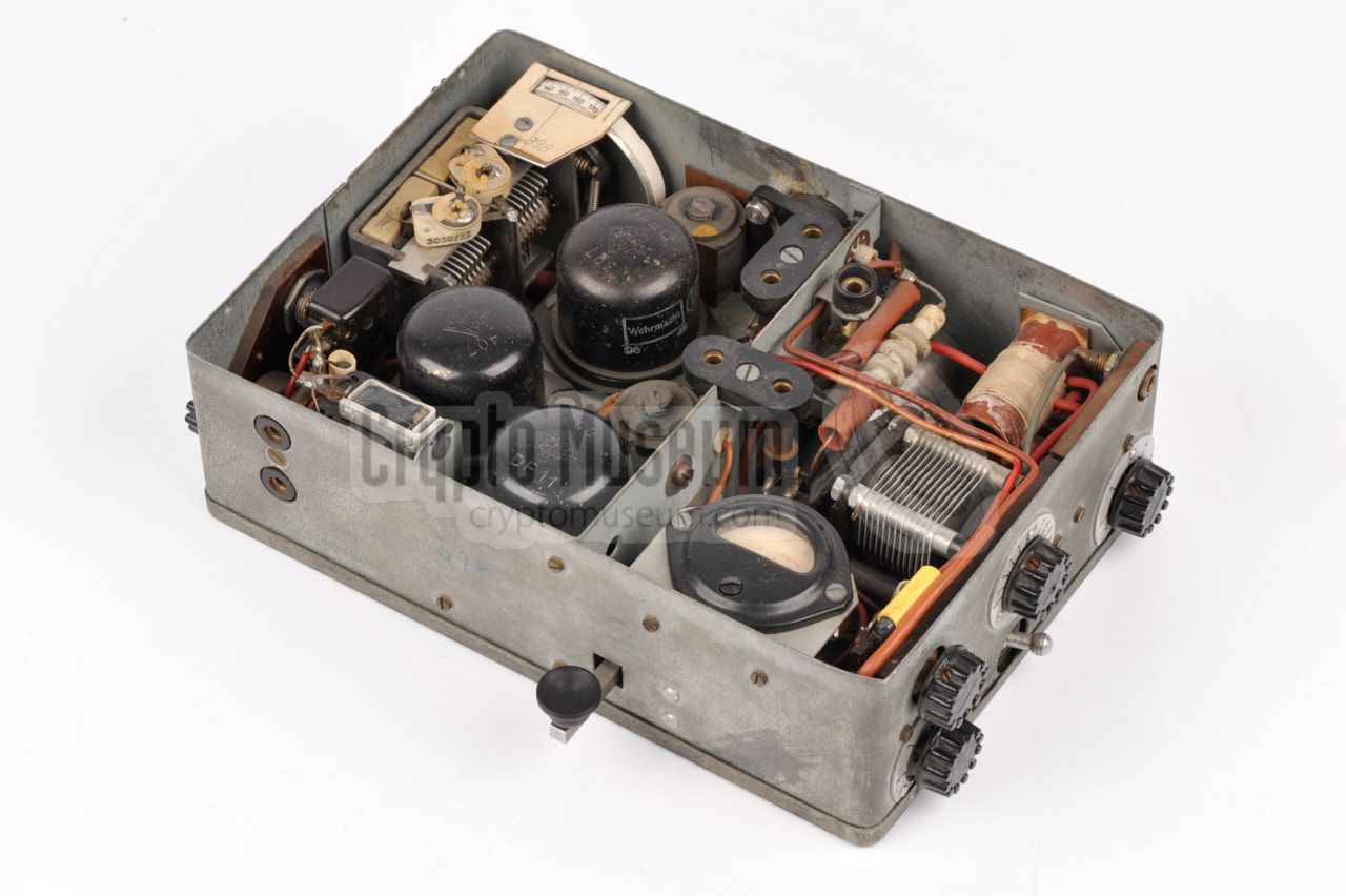
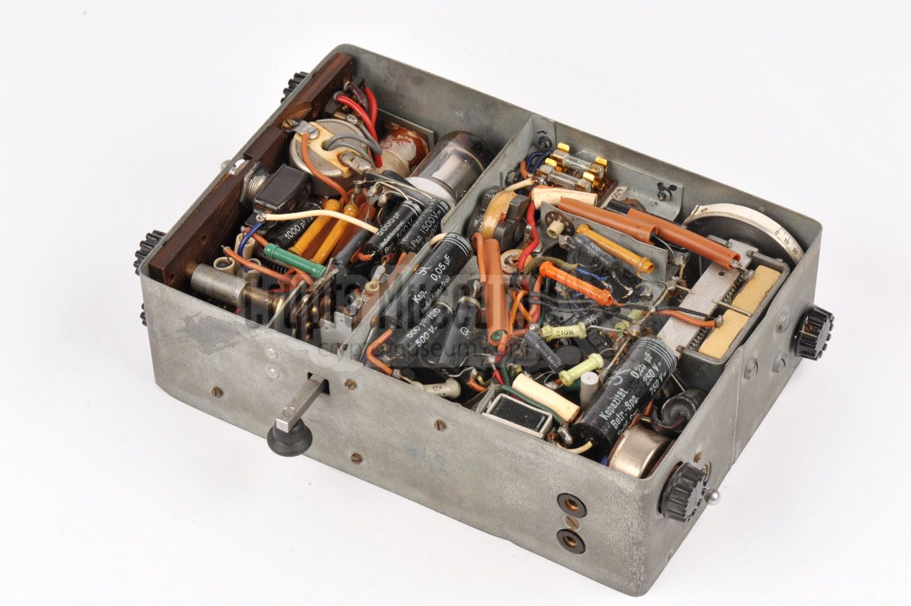
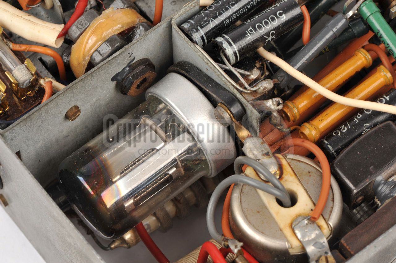
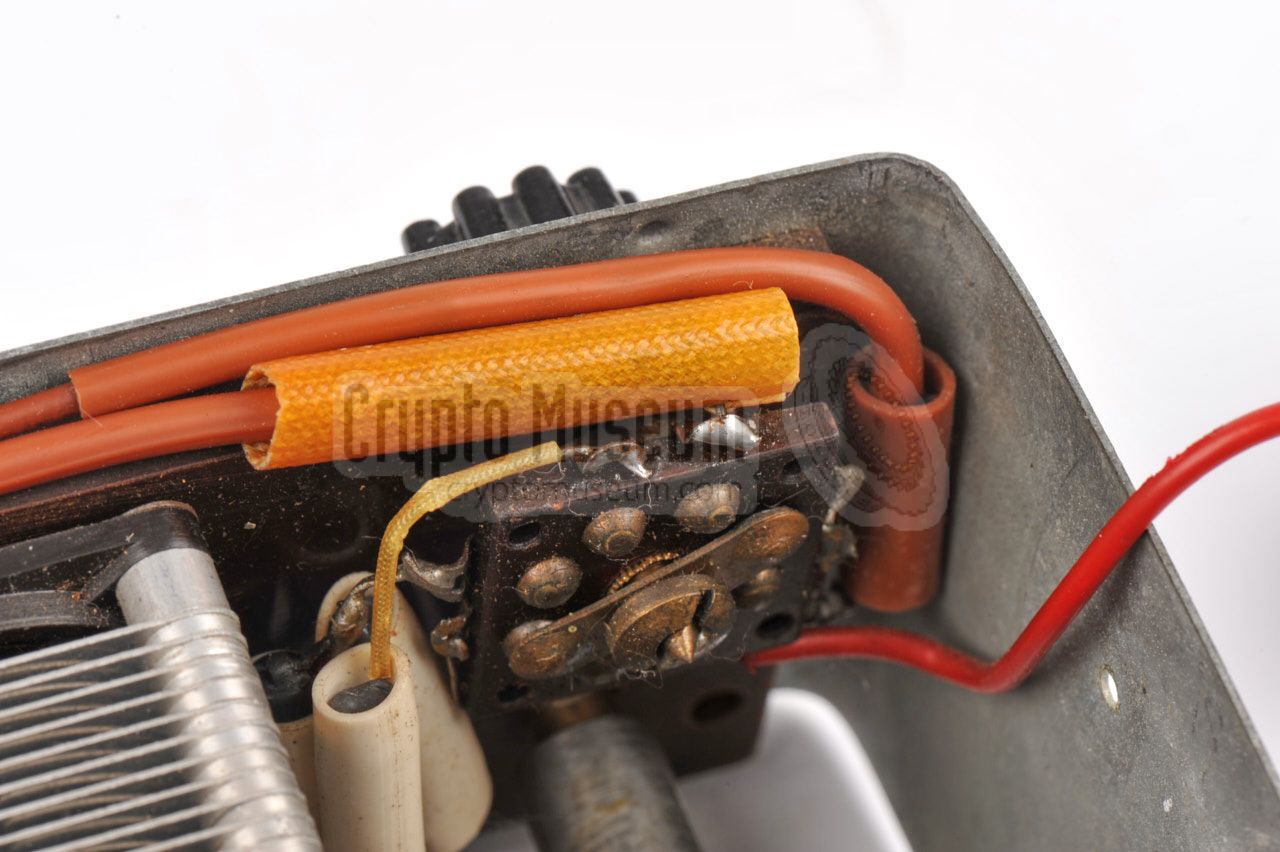
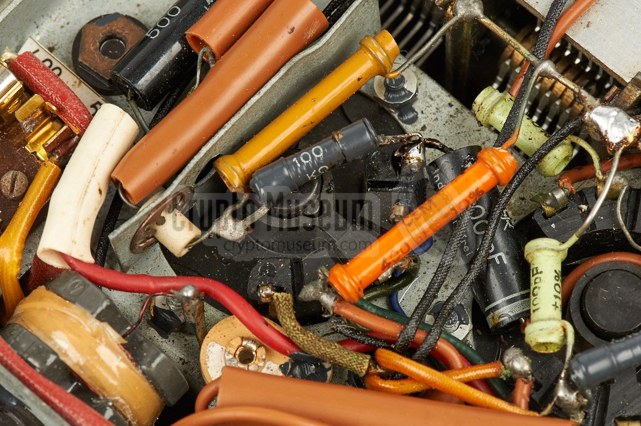
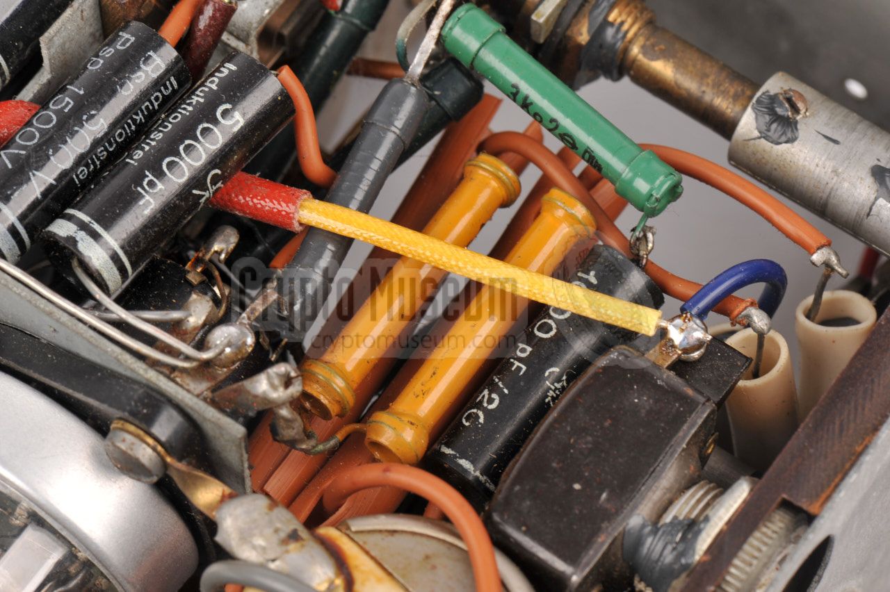
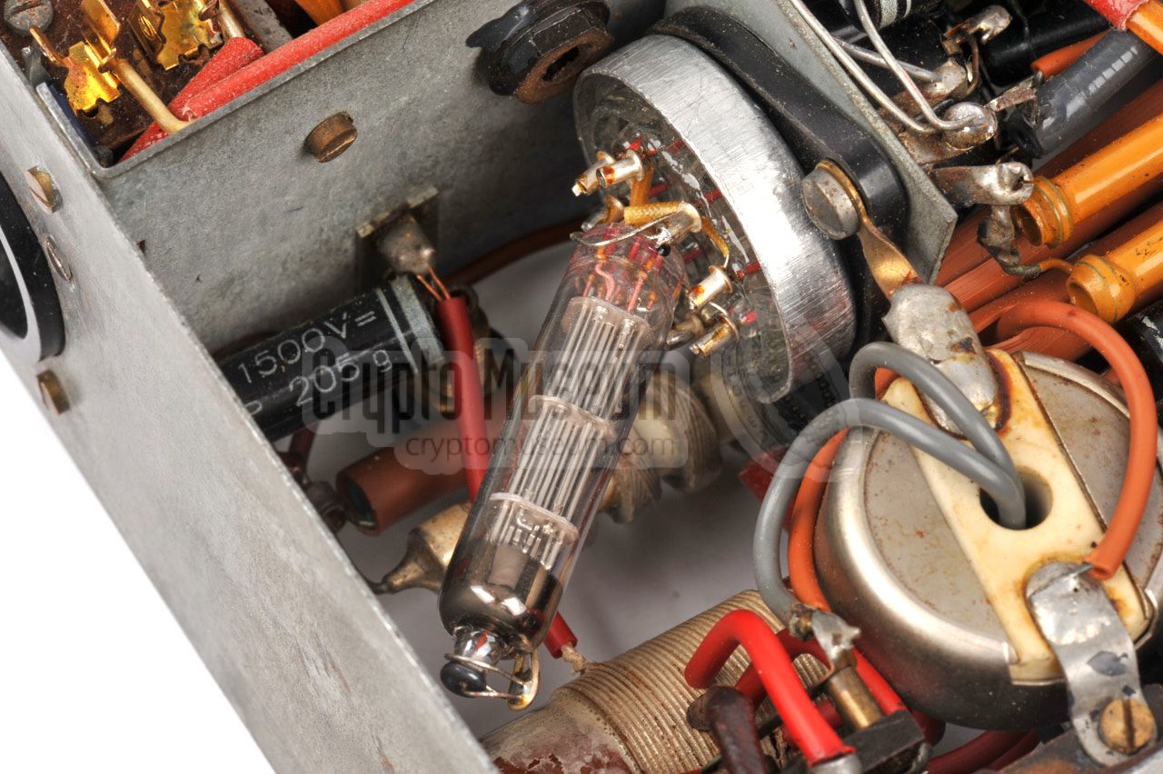
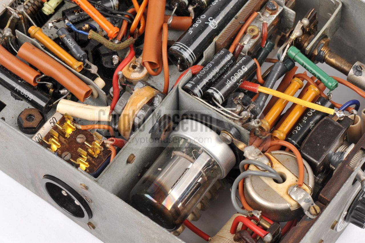
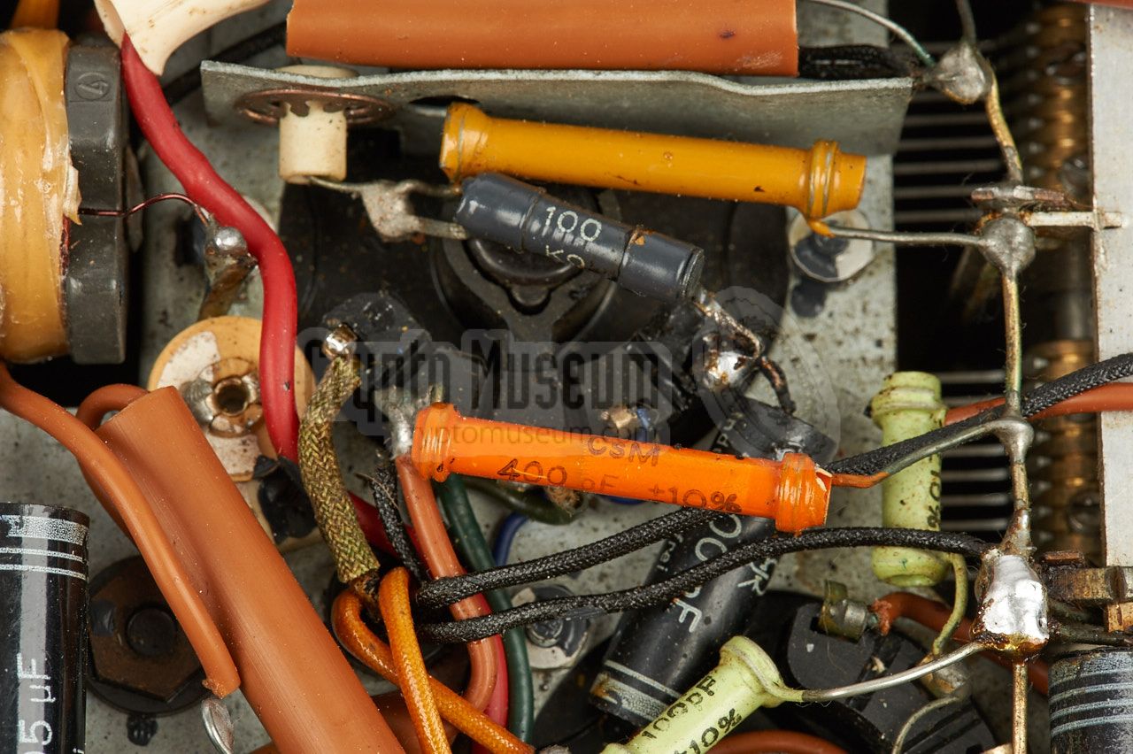
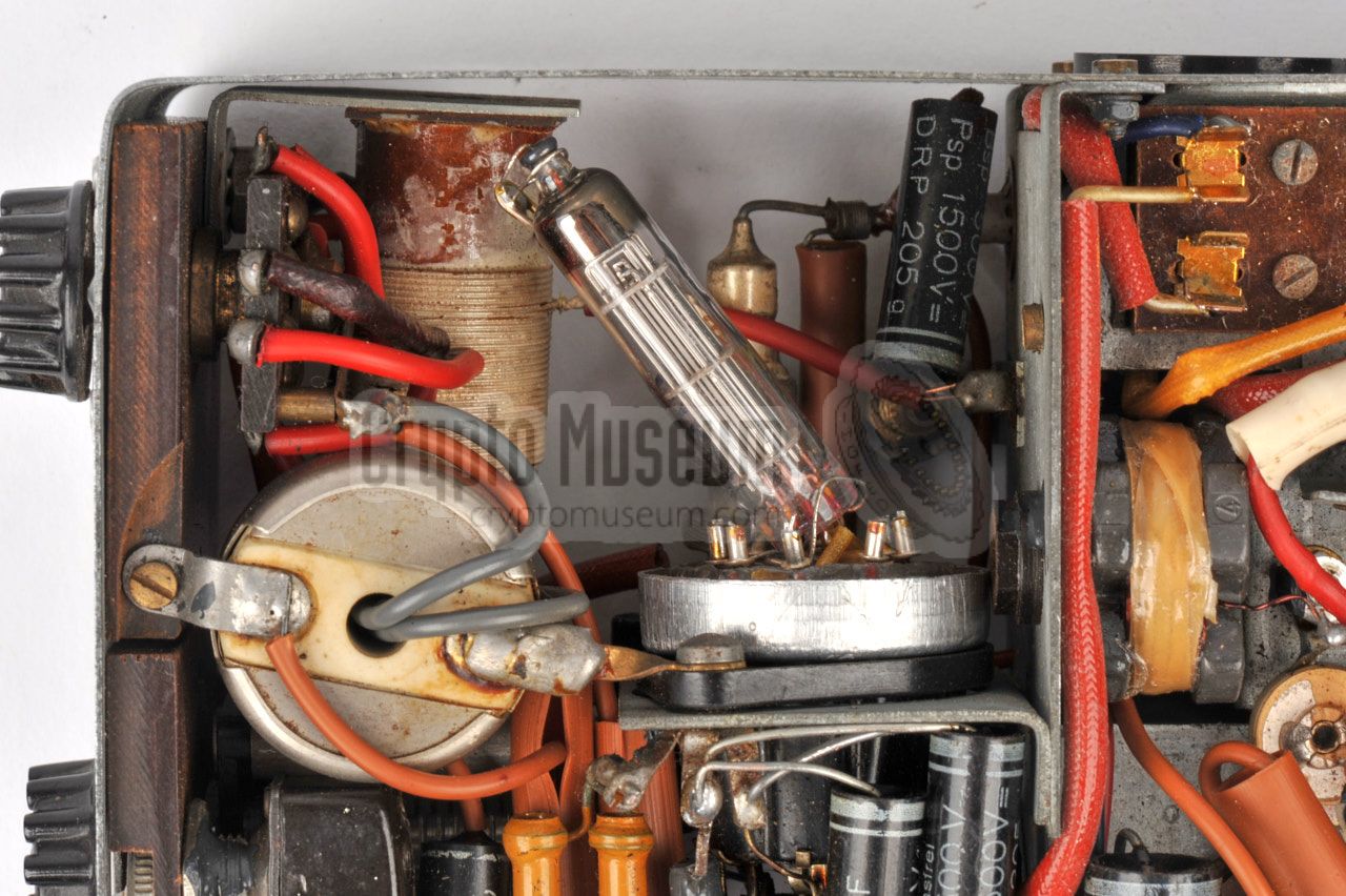
The interior of the SE-109/3 is easily accessible for repair, inspection
of the valves, swapping the fuses and for
storing the arm of the morse key
when transporting the radio set. Both the top and bottom panels can be
removed easily
like the lid of a biscuit tin, giving access to the interior.
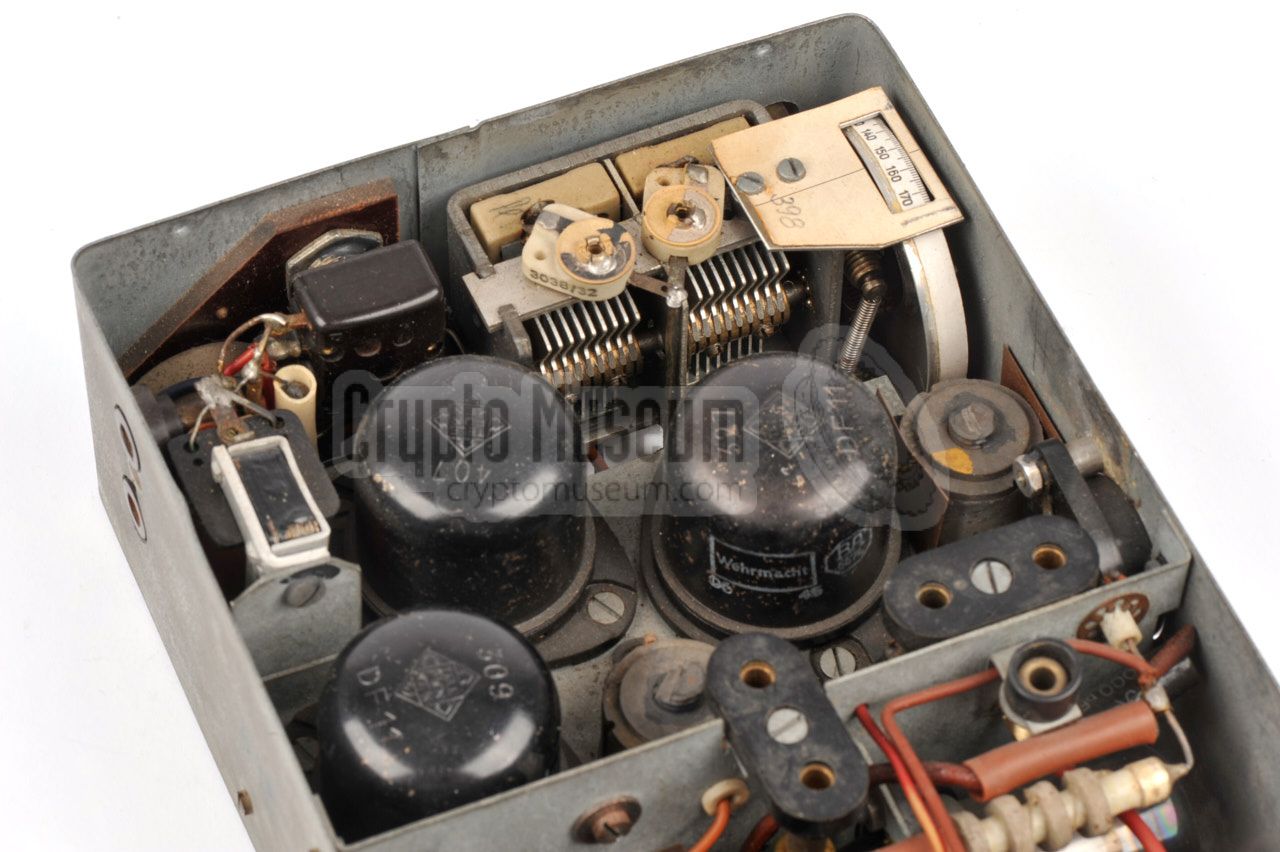
The image below shows the interior of the SE-109/3 as seen from the top.
About 2/3 of the space is taken by the receiver (left). The three large black
DF11 valves of the receiver are clearly visible.
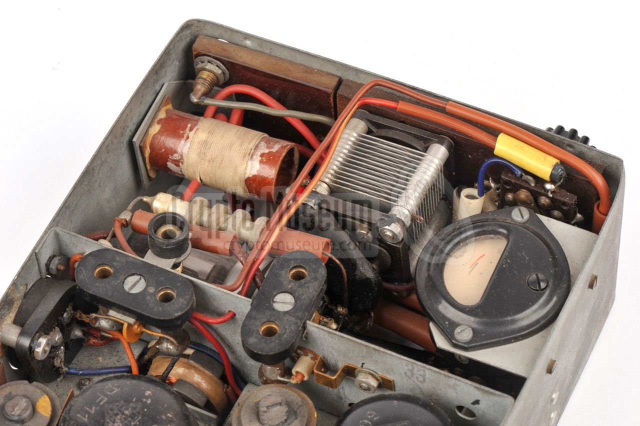
The remaining 1/3 (right) is taken by the transmitter.
This compartment also contains the indicator that is used to check the
voltages and the transmitter's output power. Receiver and transmitter
are separated by a tin panel that also accomodates the two internal
crystals (when present). The transmitter's tuned circuit consists of
a large variable capacitor at the center, and a coil with multiple
taps in the top right corner. The antenna socket is also at the top right.
The transmitter is built around one
DLL22T double-penthode valve,
that is clearly visible from bottom side of the unit. This side also
houses the passive components that are soldered directly to the valve
sockets. At the top left is the circular current transformer that
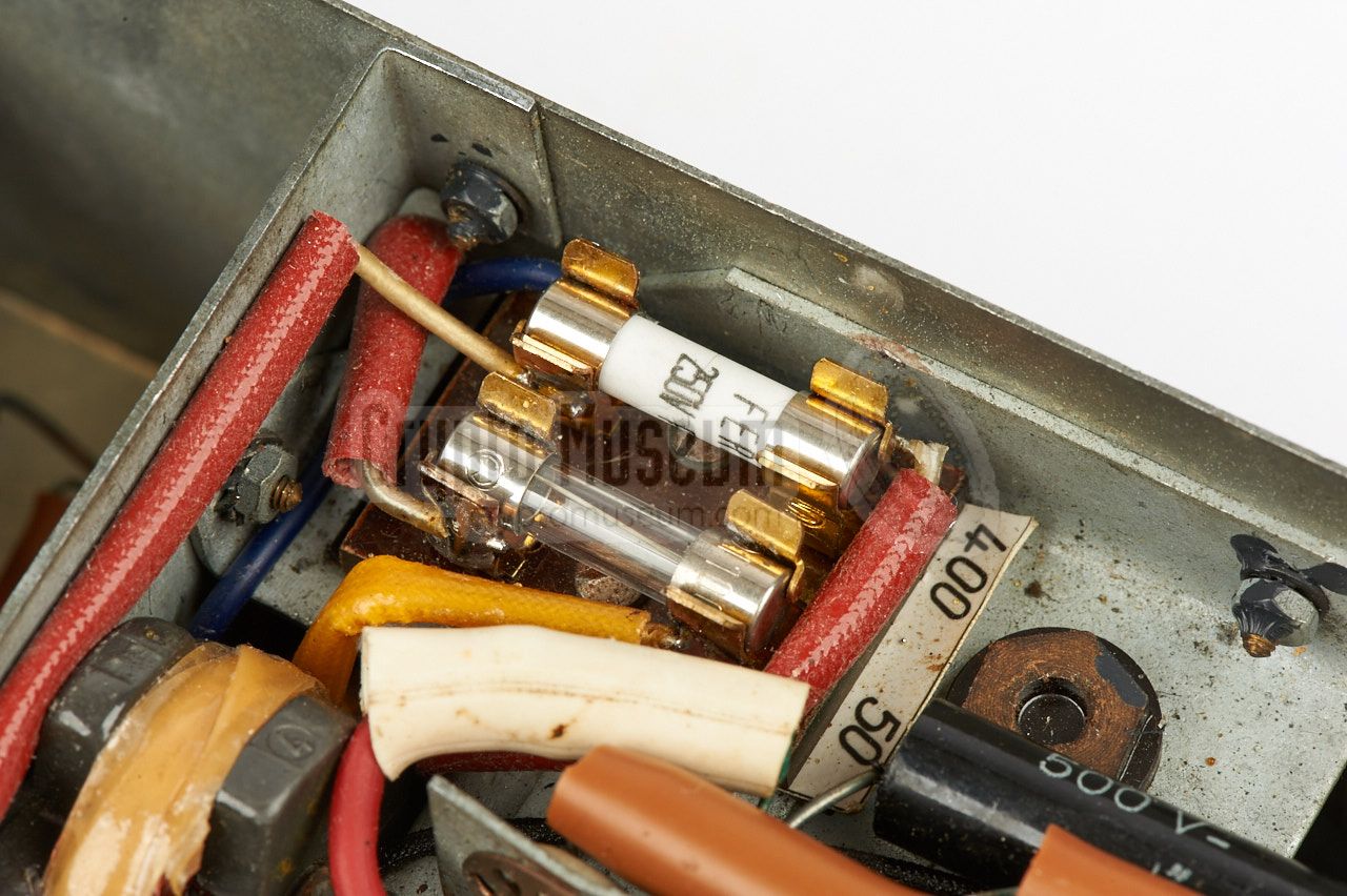
is used to measure the transmitter's output power.
The fuses for the 1.2V and 270V lines are located at the top centre.
|
The circuit diagram of the SE-109/3 has been published in Louis Meulstee's
excellent book Wireless for the Warriour Volume 4 [1], and also in
a number of publications in Radio Amateur magazines. This circuit diagram
was taken down by Gerhard Salzmann (DL2IE) from a genuine sample in 1984 [5].
Unfortunately, the transmitter had been removed from the sample from which
he took down the circuit diagram, as transmitters were illegal in post-war
Germany. He therefore made a few educated guesses, based on the design of
the transmitter of the SE-98/3.
Because the circuit of the surviving SE-109/3 radio sets, and the transmitter
in particular, is significantly different from the published circuit diagrams,
we will be discussing both variants below. We have created new circuit diagrams
that reflect the actual situation. Many thanks to Günter König (DJ8CY),
who took down the actual circuit diagrams for a presentation in 2006 [5].
|
Below is the circuit diagram of the E-109 receiver. The design is based on that of
its predecessor, the E-108, but rather than using three different valves,
the receiver of the E-109 is built with three identical DF11 valves.
As the 4-pin power socket
is inside the receiver's compartment, it is shown here as well.
The power lines to the transmitter section are at the bottom right.
|
| |
Original receiver circuit diagram [1]
|
Please note that the actual circuit and the value of some components,
differs from the original circuit diagram shown above. In 2006, German
collector Günter König recreated the
actual circuit diagram from the
device in his collection [5]. His corrected circuit diagram is shown here:
|
| |
Corrected receiver circuit diagram [5]
|
The receiver is powered by two voltages: +1.2V for the filaments (LT),
and +90V for the anode voltage of the DF11 valves (HT). Both power lines
are interrupted by the main switch (S1), but note that the +90V line
is not protected by a fuse. The +270 line is used only by the transmitter.
The circuit consists of three stages, each of which is built around
a DF11 valve. The first stage is a so-called reflex receiver [7],
which acts as the RF-stage, but also as the first AF-stage.
The second valve is the Audion stage [8], which acts as a detector.
The third valve amplifies the audio signal to headphones level and has
a 4000 Ω ear piece connected in series with the anode of V3.
Note the presence of an audio filter to improve the sound quality
of the CW tone. It consists of a 40H coil (L3) in the anode line
of V1 in combination with a 400 pF capacitor to ground, and an
LC circuit around L4 in the output stage of V3. This combination
results in the audio response that is shown in the diagram above.
The curve has its optimum around 800 Hz [5].
|
Below is the original circuit diagram of the transmitter as it has been
published over the years in a number of magazines.
This is also the circuit diagram that
is shown in Louis Meulstee's book Wireless for the Warrior Volume 4
[1]. It is uncertain whether any of surviving the SE-109/3 unit are built
according to this circuit diagram, as the ones that have been found, all have
a crystal selector. It is our impression that this circuit diagram was only
used during the development.
|
| |
Original transmitter circuit diagram as published
|
The actual circuit of the S-109/3 transmitter featured on this page,
differs significantly from the circuit diagram above. First of all, the transmitter
has two (optional) internal crystals
in addition to the external one,
plus a rotary switch to select between them (S5).
The circular internal crystals
are mounted to the panel
between transmitter and receiver and are connected
with one side to ground. As a result, the oscillator feedback loop is different.
Furthermore, the tuned circuit does not contain a transformer but consists
of a single coil with 8 output taps to match the impedance.
|
| |
Actual transmitter circuit diagram
|
The power switch is not in the 270V rail as shown in the
original diagram, but in the 1.2V rail.
It switches the filaments of the DLL22T valve and allows the transmitter
to be turned OFF to save power.
The 270V is always present and is protected
by a 50mA fuse in the receiver section.
The morse key does not
switch the anode current of the DLL22T, but controls the g2 voltage.
Another difference with the original diagram is the position of the antenna
current transformer and the addition of a second circuit to measure the
antenna output level. The first circuit (built around D1) measures the
antenna current when using a low-impedance antenna, whereas the second
circuit (D2) measures the antenna voltage in case a high-impedance antenna
is used. Both diodes, D1 and D2, are Siemens Sirutors, which are basically
stacks of copper-oxide tablets [9].
The circuit diagram above is thought to be the correct one. It has been
verified against the circuit diagram that was taken down in 2006
by Günter König, who went through the same exercise and used his diagram in a
presentation [5]. Both diagrams are identical (but have a different layout).
|
|
|
About the rotary selectors
|
|
|
The SE-109/3 has three rotary selectors that each have eight positions.
The eight positions cover the entire circle, so that each position
represents a step of 45°. The selectors have no end stop. Due to
the symmetrical layout
of two of the these switches, only four positions can be used.
The leftmost drawing above shows the internal construction of these selectors,
as seen from inside the device. A contact strip that is attached to the
shaft, connects two opposite contacts. In the example,
points 1 and 5 are connected. The next position connects 2 and 6, etc.
In order to use the switch as a 4-position selector, contacts 5, 6, 7 and 8
are usually wired together.
The transmitter's antenna selector is the only one that actually uses
all eight positions of the rotary selector. It is constructed differently
and does not interconnect the opposite contacts. The rightmost drawing shows
the construction of the antenna selector. All eight positions are used.
|
|
Just like any other Abwehr spy radio set,
the SE-109/3 is an extremely
rare find. Most radios were destroyed by RSHA personnel at the end of
WWII, and the ones that have survived may have been used by radio amateurs
(HAMs) and have probably been modified. But even if you find one that is
in near original condition, it is wise to check the circuits and the wiring
before powering it up.
|
The SE-109/3 in our collection was found in near-original condition.
No modifications were made, but a previous owner had attempted
to restore the unit and replace some of the internal power lines
that had become brittle over time.
Although proper vintage wires had been used to replace the old brittle ones,
a mistake was made when reconnecting them, probably as a result of
the differences between the circuit diagram and the actual
circuit. As a result, the +270V line was connected to the filaments
of the DLL22T transmitter valve, causing its premature death.
|
|
|
Sadly, the DLL22T is an extremely rare valve, so finding a replacement
will be very difficult if not impossible.
Furthermore, there are no plug-in compatible alternatives that have
the same form factor. Luckily, Günter König (DJ8CY) has developed a very
good temporary solution by using a Russian subminiature valve with the
same specifications. This solution is further described below.
|
Before applying the necessary voltages to the device, check the power
lines carefully to see if they are connected to the appropriate parts.
It is quite possible that a mistake has been made in an earlier restoration
attempt. Also check the 1.2V lines for short circuits and for open lines.
At this stage it might be a good idea to test only the receiver or the
transmitter, but not both. In case of the transmitter, supply the HT
voltage to the device, but leave the 1.2V line switched OFF. No current
should be drawn via the HT line. Now lower the HT voltage from 270V to
just 150V.
|
|
|
This will help to avoid any damage when things go wrong later. It also
reduces the output power of the transmitter valve. Next, apply 1.2V to
the LT line and switch ON the transmitter. The 1.2V LT line may draw up
to 200 mA. At this point, the (150V) HT line should still draw no current.
|
Ensure a proper crystal is installed in the crystal socket on top of the
device, and set the crystal selector to position 3. Connect a wire antenna
to the transmitter's antenna socket, and connect a proper counterpoise
to the G-socket at the top.
Set the meter-selector to PLATE TR. so that the transmitter's
output power can be measured.
Once the valve has heated up, press the morse key and check the currents.
The HT line should now draw a modest current in the 40 mA range. If this is
the case, carefully tune the oscillator tuning knob so that the system starts
oscillating.
|
|
|
If this is the case, you should see a reading on the meter. Note that you
may have to select a different tap on the tuning coil in order to properly
match the impedance of the connected antenna. In any case, find the combination
of the antenna matching selector and the oscillator tuning
that gives a maximum reading on the meter. You should now be able to transmit.
|
If all goes well, you may now raise the HT voltage to +270V. The transmitter
should then produce an output power of 2 - 3 Watts. When using a replacement
valve (see below), it might be wise to use a maximum voltage of, say, 200V.
With the receiver, we follow the same procedure. First apply the 90V HT
voltage and verify that some of that voltage arrives at the anode of each
DF11 valve.
In our case we had to restore the wiring around the socket of the first valve,
i.e. the reflex stage, as someone had mirrored the connections in a previous
restoration attempt.
|
|
|
At this stage the HT line should not draw any current. If this is the case,
connect a pair of 4000Ω headphones and apply 1.2V to the LT line
by switching ON the receiver. The LT line should now draw 60-75 mA.
At the same time, you should hear some noise in the headphones. Note that
you may have to turn the REACTION knob for the optimum noise level.
Now connect an appropriate antenna and counterpoise and try to tune-in
to a signal, whilst readjusting the REACTION knob.
|
|
|
Making a replacement for the DLL22T
|
|
|
|
The DLL22T is extremely rare and there are no plug-in
compatibles with the same form factor. In 2006 however, collector
Günter König [5] developed a gap-fill solution by using a
Russian 1P24B
(1П24Б) miniature pencil valve and soldering it to the base of
a broken or dismantled octal valve.
|
The 1P24B is used in Cold War
Russian spy sets
like the R-353.
It has the same specifications as the DLL22T, but is much smaller,
allowing it to be mounted in the existing space without any modifications
to the wiring of the SE-109/3.
And more importantly: the 1P24B is widely available.
If you have a similar radio set with a broken DLL22T, you might want to
build a functional replacement for it. Here is how to do it.
First find a Russian 1P24B pencil valve, plus an old valve with
a loctal base, such as the Russian 2Ж27Л,
that will be disassembled as we need its base.
|
|
|
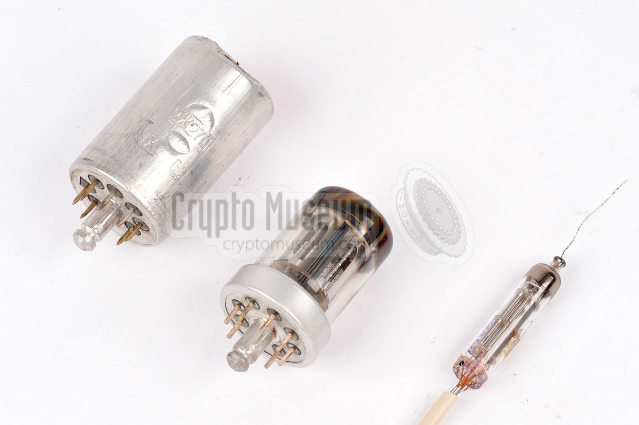
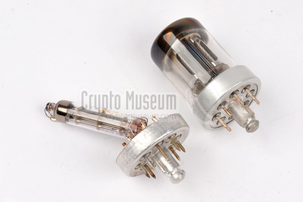
The image above shows the original DLL22T valve (centre), the miniature
1П24Б (right)
and the 2Ж27Л in its aluminium enclosure (left). Inside this
enclosure is a common glass valve. Use a small saw to cut off
the base of the aluminium cylinder, approximately 5 mm from the bottom.
|
Now comes the tricky part:
cut off the base of the glass valve,
approx. 5 mm from the bottom. This can best be done with a rotating
saw blade such as a Dremel. Once this is done, remove the interior from the
demolished valve, but leave the contact pins at the base
intact, as we will need them later for mounting the replacement valve.
The contact pins on which the old valve interor was mounted,
should now be made solderable. This means that a thin layer has to
be milled-off from each pin. This can be done with a dental drill.
Try whether the pins can be soldered.
|
|
|
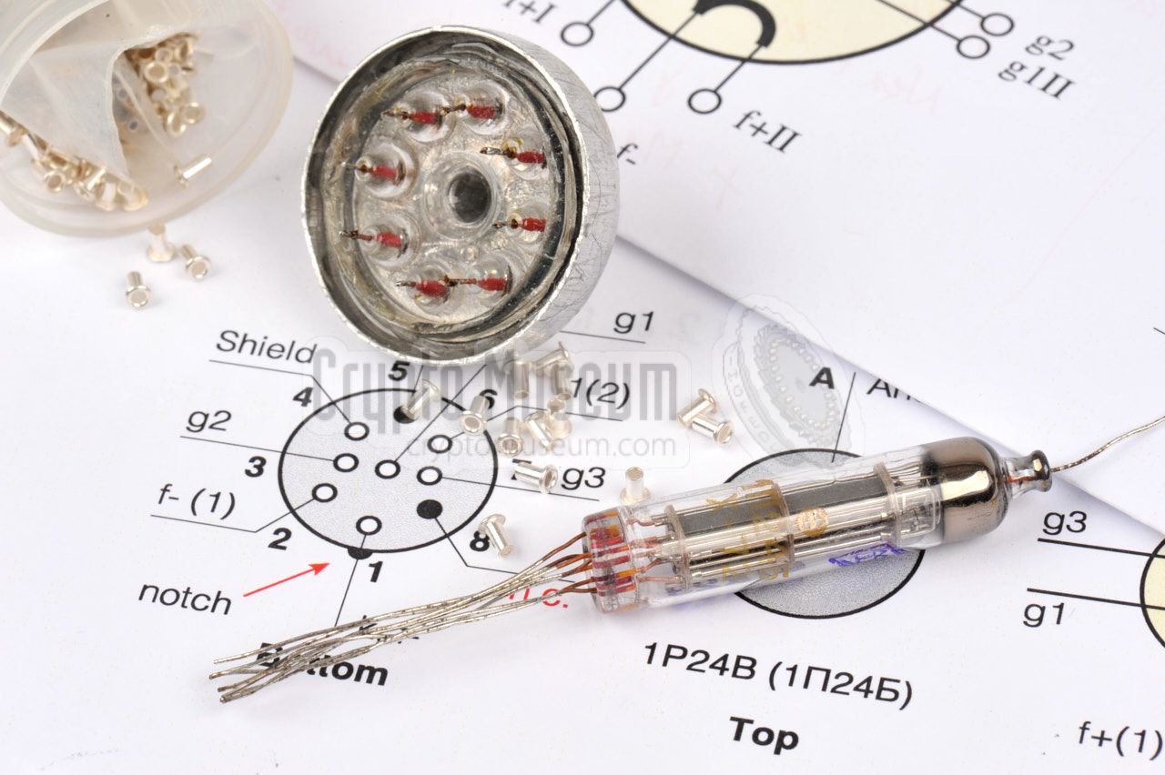
This leaves us with a glass base with contact pins on both sides,
and a aluminium holder in which the glass base can be fitted.
Affix the glass base inside the aluminium holder using a strong
two-component adhesive and wait until it is hardened. This may
take up to 12 hours or even longer.
|
Once the adhesive has hardened, we can build up the replacement
valve. Place the newly made base in a small vice and prepare the
base for soldering. At this point it might be a good idea to
solder a bridge between the pins a(1) and a(2) and between
pins g1(1) and g1(2) of the base.
When Günter König built his replacement valve in 2006, he
mounted the 1P24B pencil tube as deep inside the new base as
possible. However, as the 1P24B is a rather long valve, we
decided to mount it under a 45° angle, giving it a bit more
space and protecting the anode at the top.
|
|
|
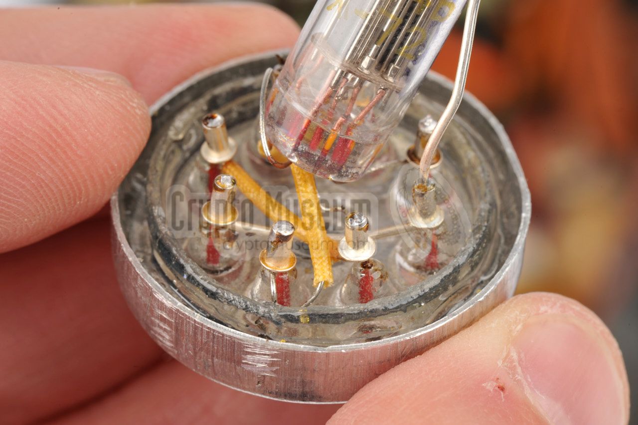
Now solder the relevant wires of the russian pencil tube onto
the pins of the base. In our case, we have used
small silver-plated rivets in which the wires of the valve are
joined with a contact pin of the base. This makes soldering much
easier and adds to the overall strength of the construction.
|
The image above shows how this can be done. The wires of the
1P24B are very thin and are very close together, so be careful
not to cause any short circuits. Use insulation where necessary.
The last wire to be connected is the anode of the 1P24B, which
is at the valve's top. To make the construction stronger,
a thicker wire is used.
When you are finished, check and re-check all wires to ensure
that the correct lines of the 1P24B valve are connected to the
appropriate pins of the base. After that, check it again.
|
|
|
If the base is correctly wired and no shorts are found, your
replacement valve is ready for use. Install it in the socket
and turn on the power. Ensure that you use
a proper laboratory power supply unit with a current limiter,
to avoid damage in case you made a mistake.
Furthermore, it might be wise to reduce the HT voltage to around
+150V, which is the nominal voltage of the 1P24B.
This will protect the valve against excessive dissipation
caused by antenna mismatches.
If all goes well, you should now be able to demonstrate the transmitter
of your SE-109/3 again.
In case you want to give this method a try, the above diagram shows how
the replacement valve should be wired to the existing socket. Note that
both sockets are seen from the bottom of the valves. Do not use the
original DLL22T valve as the base for the construction, as it is too rare.
Instead, use a cheap Russian surplus valve with a loctal base,
like the 2Ж27Л that we used here.
➤ Pinout of the 1P24B valve
➤ Pinout of the DLL22T valve
|
|
|
Comparison of the two valves 1
|
|
|
| | DLL22T | 1P24B | Remark |
|
|
| Uf | 1.2 ··· 1.4 V | 1.08 ··· 1.34 V | Both filaments connected in parallel |
| If | 0.2 A | 0.255 A | Both filaments connected in parallel |
| Ua | 120 / 150 V | 150 / 300 V | Nominal / Max |
| Ug2 | 120 V | 125 / 200V | Nominal / Max |
| Ia | 15 mA | 17 mA | DLL22T: 2 x 7.5 mA |
| Ig2 | 4 mA | 3 mA | DLL22T: 2 x 2 mA |
| S | 1.5 mA/V | 2.8 mA/V | Slope |
| Pa | 1.5 W | 2.5 W | Nominal values. DLL22T: 2 x 0.75W |
| J | ? | < 3 µS | Impulse @ Ua = 400 V, Ug2 = 300 V, Ik = 800 mA |
|
From the above table it is obvious that the DLL22T is driven well beyond its
maximum ratings. Although this is common practice with transmitter valves, it
significantly reduces the valve's life. Furthermore, this can only be done
when the circuit is actually oscillating (i.e. when a crystal is present and
the tuned circuit is in resonance), as otherwise there will be no current
limiting.
The same is true for the russian 1P24B valve that was used in Cold War
Soviet spy radios sets like the R-353
and the R-354.
In the R-353 it is used
in one of the transmitter's driving stages,
and in the R-354, three of them are
used in parallel in the PA stage to produce 10 Watts of RF power.
|
-
Table kindly supplied by Günter König (DJ8CY) [5].
|
|
|
Demonstration of the SE-109/3
|
|
|
|
In this video, Norwegian collecor
Helge Fyske
demonstrates how the SE-109/3 can be operated in the field
with a simple antenna, by taking the device to a park
near his museum
and operating it on one of the amateur radio bands, using his amateur
callsign LA6NCA. Another radio amateur – callsign LA5FH – answers the call
and confirms that he receives a loud and clear signal from him.
|
|
The SE-109/3 is powered via the 4-pin circular male socket at the rear.
This is a so-called break connection (German: Brechkupplung), that
was also used by the German Luftwaffe (Air Force) during WWII.
Below is the pinout when looking into the male socket, from the rear of the device.
|
- HT +270V TX (via 50 mA fuse)
- 0V (Ground)
- LT +1.2V filaments (via 400 mA fuse) 1
- HT +90V RX (unprotected)
|
|
-
In some publications this line is erroneously designated as +12V.
|
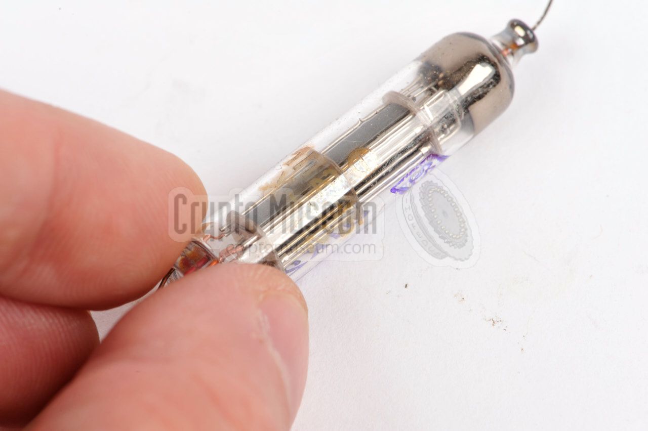
The DLL22T valve that is used in the S-109/3 transmitter,
was manufactured during World War II by Tungsram in Budapest (Hungary).
The suffix 'T' denotes that it was made by Tungsram. It was also
made by Philips/Valvo as the DLL22, but without the 'T' suffix. 1
Below is the pinout of the Tungsram DL22T. At the left is the circuit symbol.
At the right is the bottom view of the valve [6].
|
-
The pinout of the Philips/Valvo DLL22 should be identical to that of
the the Tungsram DLL22T, but the information in the surviving valve
databooks is conflicting [6]. Furthermore,the Philips/Valvo variant
might be higher, and may not fit inside the SE 109/3.
|
The DF11 is a black metal German valve, made by Telefunken, of which
three are used in the receiver. It is a directly heated Penthode that
is suitable for RF, IF and AF applications. It has an LT voltage of
1.2V and a typical Anode voltage of 90V.
Below is the pinout of the DF11.
Note that the terminals of the unused pins (marked n.c.),
are used as a mounting hub for other components.
➤ DF11 datasheet
|
The Russian valve 1P24B (1П24Б) is not used in the SE-109/3 radio set,
but is shown here as a possible replacement for the extremely rare DLL22T.
The 1P24B is very similar to the DLL22T, but has a different anode voltage
and different maximum ratings. The pinout is given below.
➤ 1P24B datasheet
|
Model SE-109/3 Dimensions 6 × 14 × 20 cm Weight 1.7 kg
|
Model E-109 Frequency 3.2 - 6.5 MHz 1 Modulation AM, R/T (A1, CW) Valves (tubes) DF11 (3x) Sensitivity < 2µV
|
Model S-109/3 Frequency 3.3 - 7.5 MHz 1 Modulation CW Valve (tube) DLL22T Output 3W
|
-
This is the standard frequency range. Other ranges were used for
specific missions [1].
|
- Louis Meulstee, SE 109/3
Wireless for the Warrior - Volume 4.
ISBN 0952063-36-0. September 2004.
- Arthur Bauer, Some Aspects of the German military Abwehr wireless service...
...during the course of World War Two
15 September 2003. p 10. 1
- CQ-MB, Description of the K. Rosinski Kleinhörer
DASD club magazine (German). August 1937. Page 125.
- CQ-MB, Advert of the K. Rosinski Kleinhörer
DASD club magazine (German). Date unknown. 2
- Günter König (DJ8CY), Das Agentenfunkgerät SE 109/3
Power Point Presentation. Langebrück/Dresden, 28 April 2006.
Personal correspondence September 2016. 3
➤ SE 109/3 Circuit diagram
- Radiomuseum and contributors, DLL22T
Website. Retrieved September 2016.
→ See also DLL22
- Wikipedia, Reflex receiver
Retrieved September 2016.
- Wikipedia, Audion receiver
Retrieved September 2016.
- Radio Museum and contributors, Siemens Sirutor
Retrieved September 2016.
- Archiv Rudolf Staritz, various photographs, circuit diagrams and descriptions
Obtained from the Heinz Lissok Archive, June 2012. #CM301583.
- Rudolf F. Staritz, Image of Maus morse key and Rosinski Kleinhörer
Reproduced here by kind permission of the author.
Retrieved October 2016 via Arthur Bauer [2].
- Various collectors, personal correspondence
The following collectors have contributed to this page:
Manfred Bauriedel, Helmut Fünfgelder, Thomas Höppe, Günter Hütter,
Günter König, Rudolf Staritz.
|
|
-
Note that in this document the SE-109/3 is erroneously called SE-108/3.
-
Document kindly supplied by Thomas Höppe.
-
Reproduced here by kind permission from the author.
|
|
|
|
Any links shown in red are currently unavailable.
If you like the information on this website, why not make a donation?
© Crypto Museum. Created: Tuesday 27 September 2016. Last changed: Tuesday, 28 April 2026 - 10:30 CET.
|
|

|
|
|
|


![SE-109/3 with serial number 683, with storage case and PSU [10]](img/se109_case_psu.jpg)


![K.Rosinski Kleinhörer in an advert of 1937 in the DASD amateur magazine CQ-MB [3][4].](img/rosinski_thumb.jpg "image # rosinski_adv.jpg")

![K.Rosinski Kleinhörer in an advert of 1937 in the DASD amateur magazine CQ-MB [3][4].](img/rosinski_adv.jpg)


![Audio response of the E-109 receiver [5]](svg/e109_audio.svg)


