|
← Germany WWII Abwehr
Abwehr spy radio set
The SE 98/3 was an
espionage transmitter/receiver
developed during WWII by OKW-Aussenstelle Berlin-Stahnsdorf 1
for use by the German Security Service,
the Abwehr, mainly in the Eastern war
theatre.
The device was introduced in 1941 and was manufactured by OKW Stahnsdorf. From 1942 onwards it was made by OKW-Aussenstelle
Wurzen. It was one of the most widely used
Abwehr radio sets
during WWII and is in fact the container version of the
SE-97/3 suitcase radio.
|
The radio set consists of a small 3 Watt
S-98/3 crystal-operated transmitter
and an adjustable E-98 receiver that are mounted on
a subframe
together with a small power connection block.
The subframe slides into a larger frame that also holds the
removable batteries.
The batteries are held in place by an elastic band at either side of
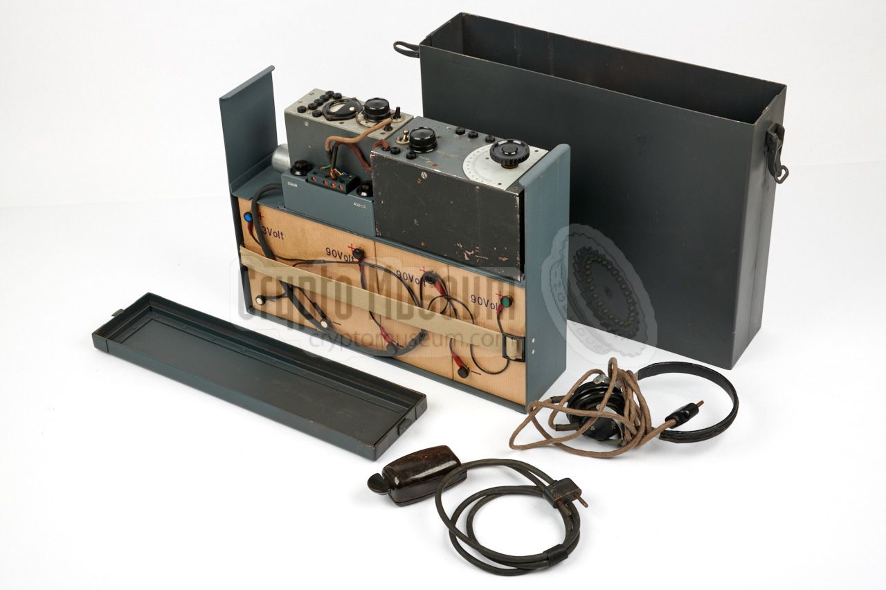
the frame. The complete assembly slides into a grey metal container with
a watertight top lid.
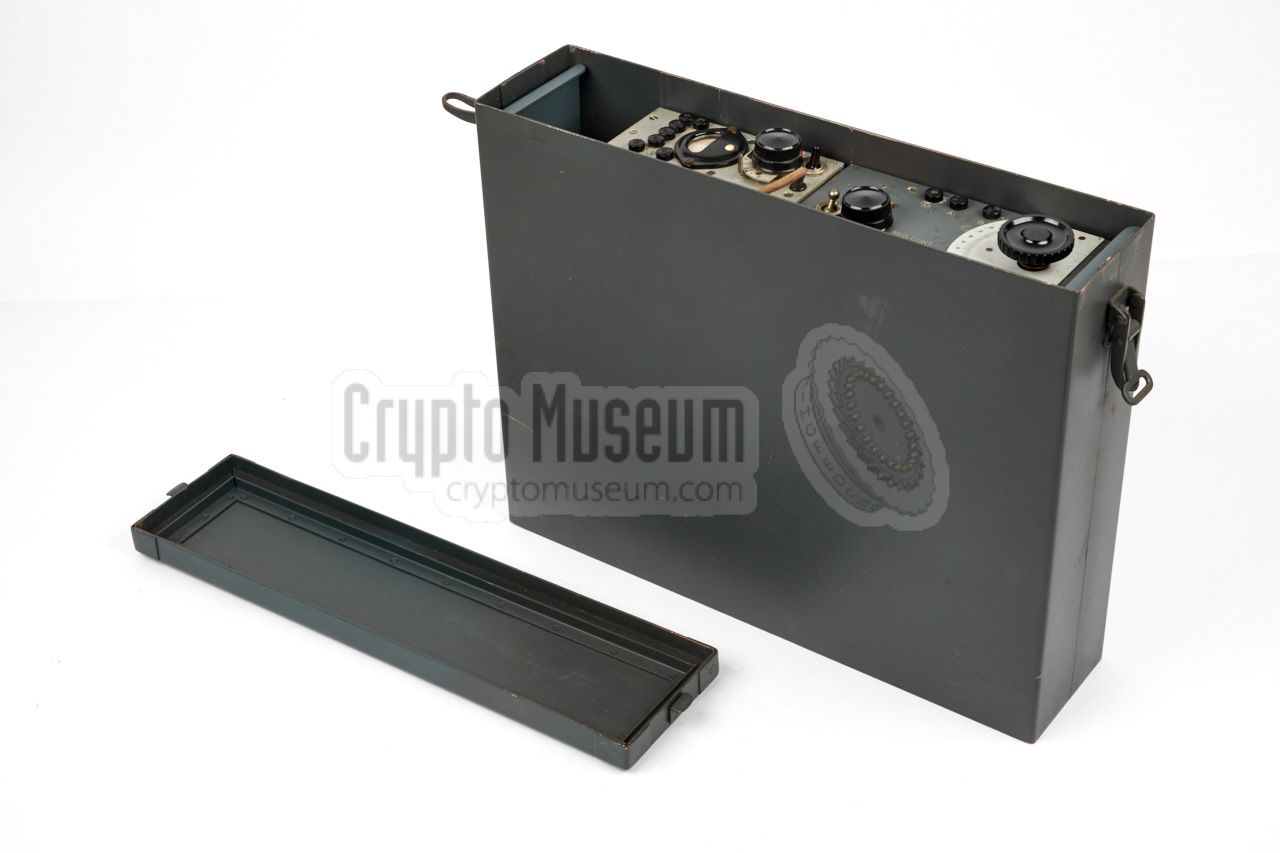
The image on the right shows a typical SE-98/3 set inside its metal
container with removed top lid, complete with morse key and headphones.
|
|
|
The radio is powered by four internal batteries
that last one full year when using it 15 minutes each day [2].
Despite the fact that the SE 98/3 was one of the most widely used
Abwehr radio sets,
only very few have actually survived. Most sets were lost during
the war, or were destroyed by its users at the end of WWII.
As a result it is arguably one of the most rare Abwehr sets today.
|
-
OKW = Oberkommando der Wehrmacht (Supreme Command of the Armed
Forces) in Nazi Germany during the Second World War.
Aussenstelle = Outpost.
|
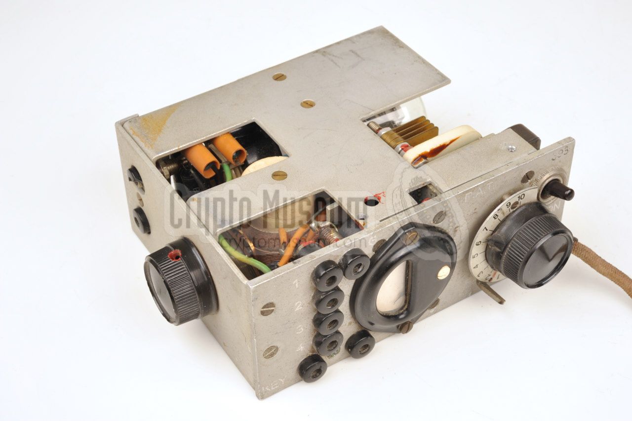
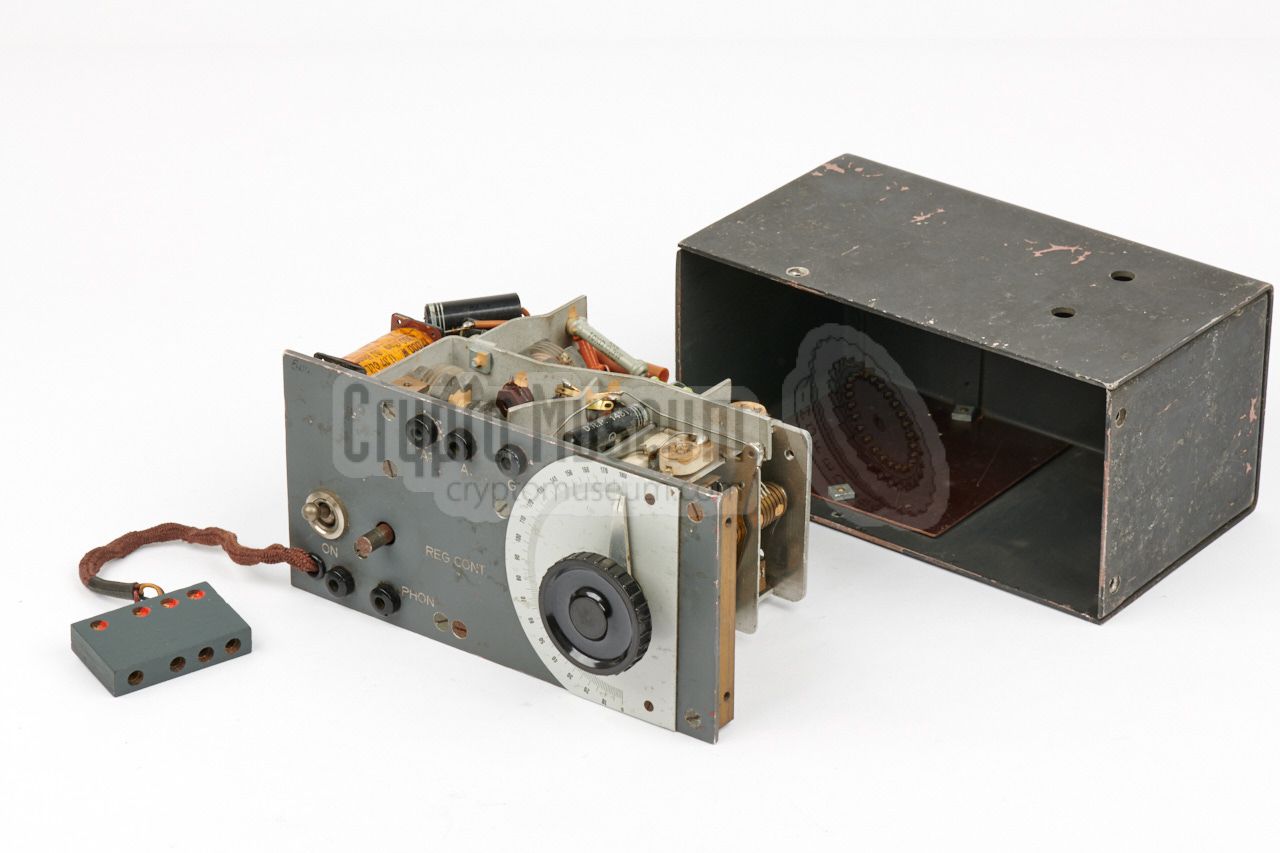
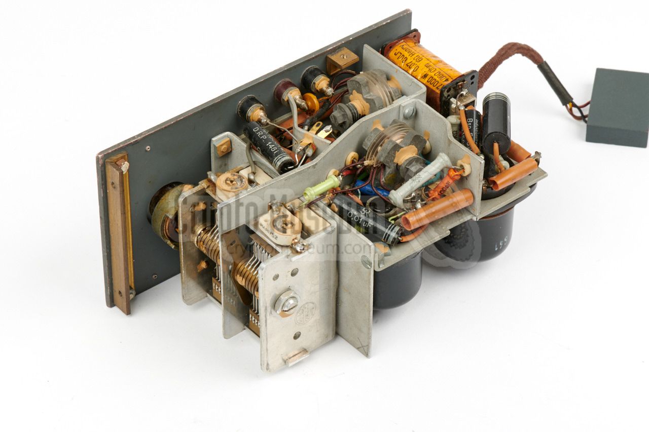
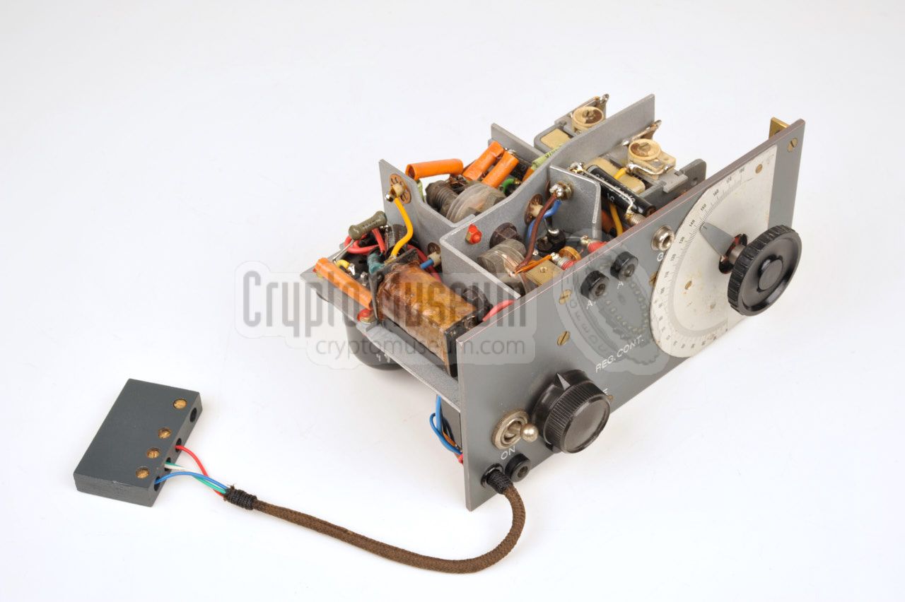
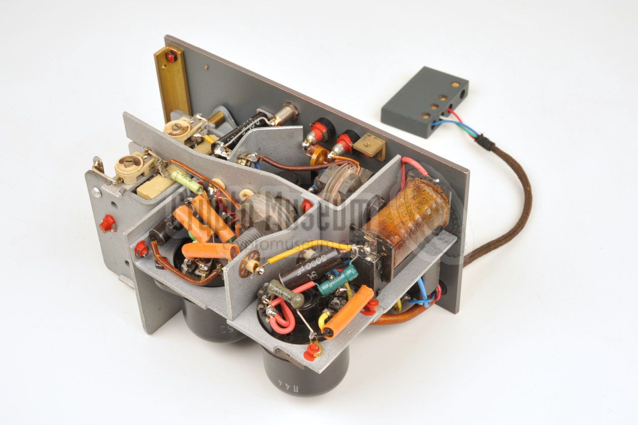
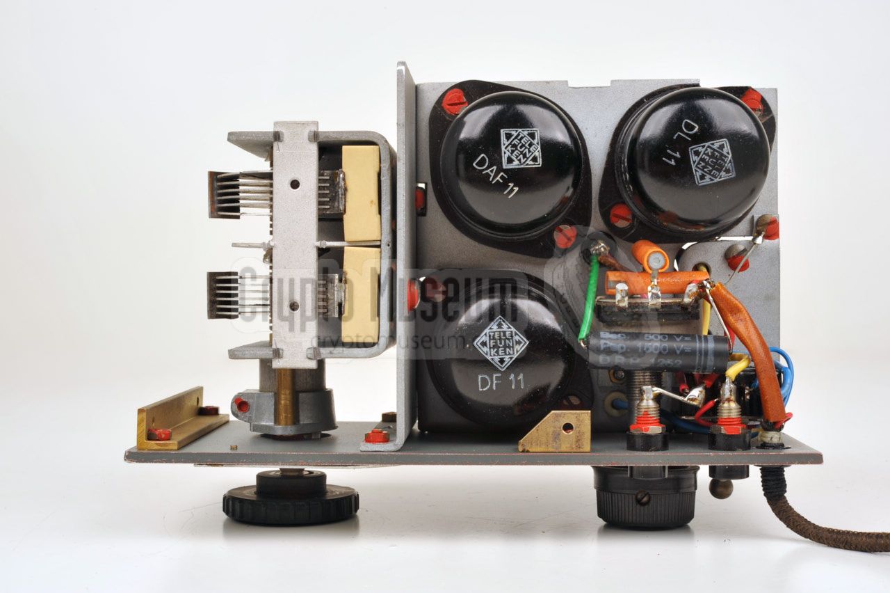
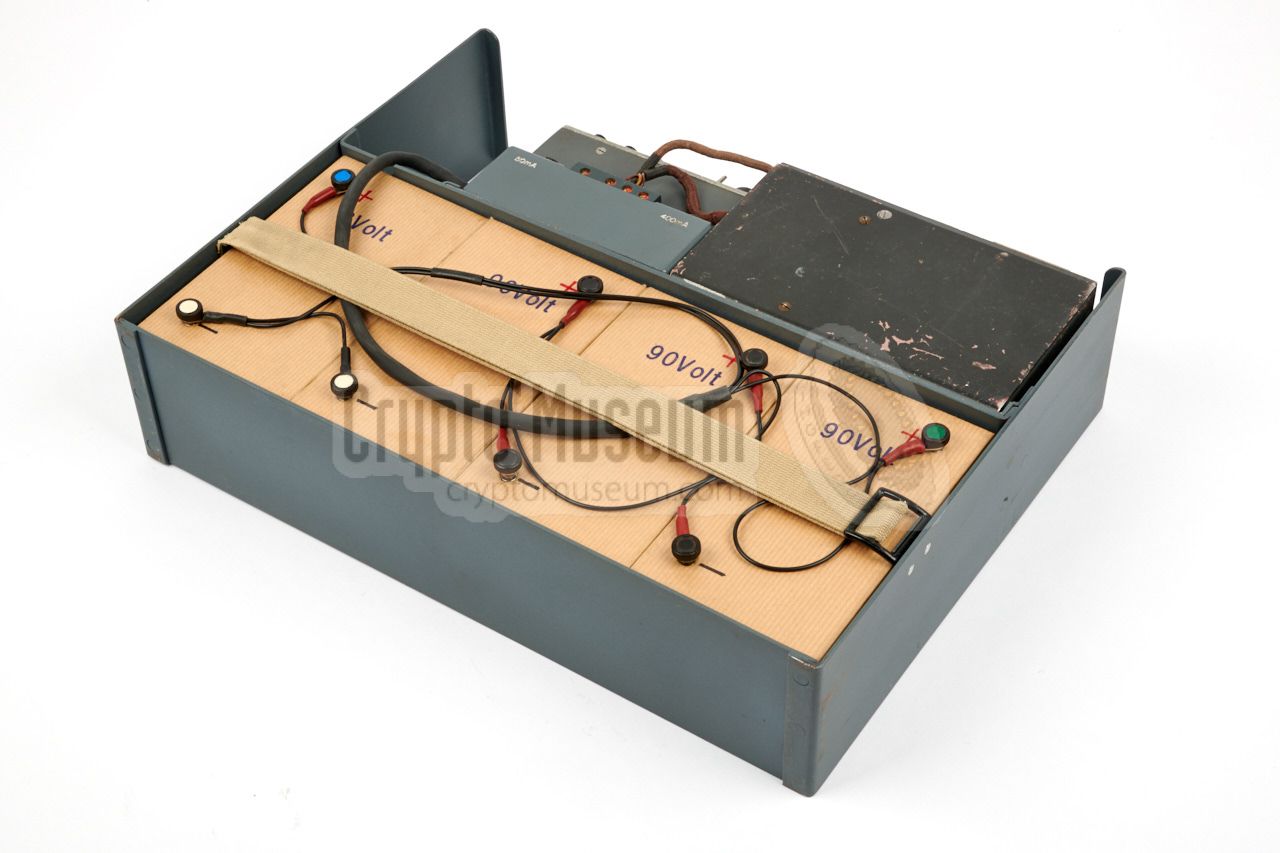
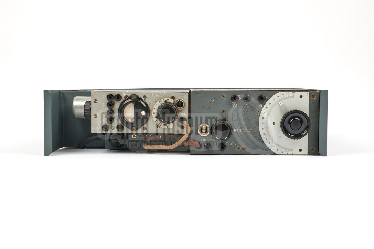
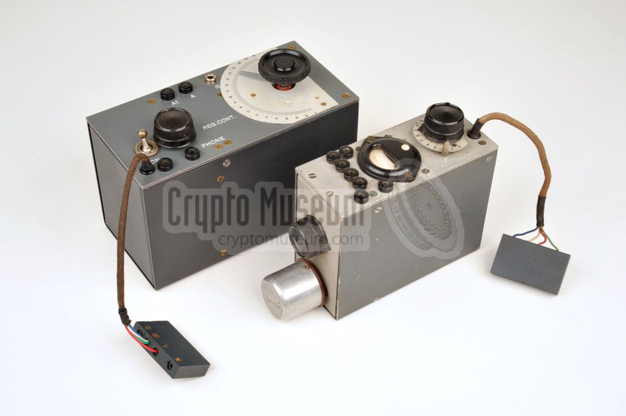
The diagram below shows the SE-98/3 after it has been removed from its
storage container. Although it can be used whilst seated inside the container,
we have removed it here to show the various features of the set, sitting on a
U-shaped sub-frame. The lower half of the frame is occupied
by the batteries that provide the LT voltage (3V)
and the HT voltages (90 and 270V).
The upper half of the frame holds a subframe with the receiver (right)
and a small transmitter, both of which are connected to the small
terminal block in front of the transmitter.
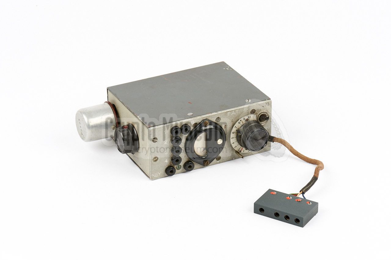
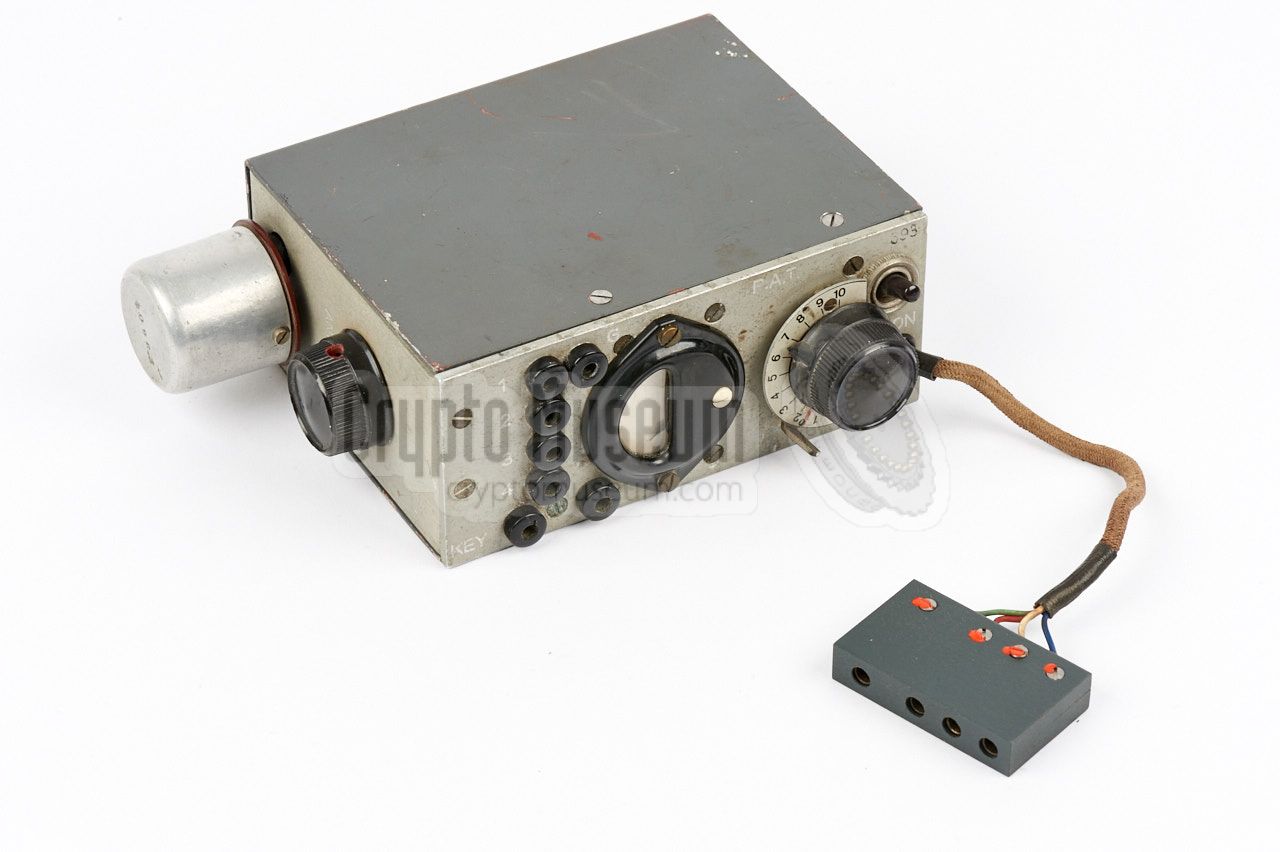
The S-98/3 transmitter is the smallest of the two units and is built
around a KL2 valve that delivers an RF output power of 3 Watts
in CW (A1).
It is shown below with a suitable crystal installed at the left.
The E-98 receiver is the largest unit of the set and is mounted at the right
half of the subframe. It is built around three metal valves
(DF11, DAF11 and DL11)
and has a frequency coverage of 2.1 to 8.2 MHz, whilst the transmitter covers 3
to 8 MHz. It has two antenna inputs, one of which is fed through an attenuating
capacitor, and a socket (ground) for connection of the counterpoise.
|
|
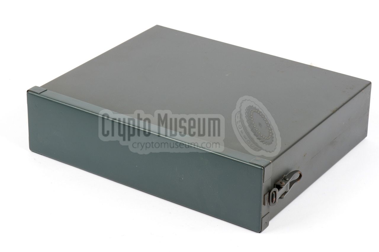
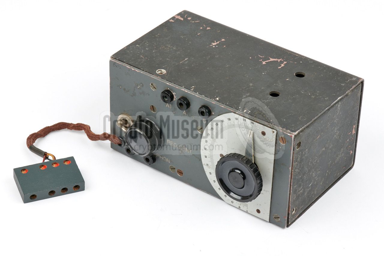
The SE-98/3 came pre-installed in a watertight grey metal container which
also holds the one year lasting batteries. The container was usually transported
inside an unobtrusive suitcase, along with ancillaries like
headphones, morse key, crystals,
antenna wires, spare parts and tools.
|
The SE-98/3 came in the grey metal container shown in the
image on the right, that also holds the batteries.
Transmitter
and receiver
can be accessed by removed the top lid of the case, which is held in place
by two clamp-locks at the short sides. It measures 38.5 x 28 x 10 cm and weighs
4000 g (including all parts).
After removing the lid, the radio set can be operated from within the container.
Although the case offers space for the ancillaries, such as the
morse key and
the headphones, those were commonly kept in a separate box.
|
|
|
The transmitter measures just 13 x 10 x 5 cm and weighs 750 grams.
It is housed in a metal enclosure that was available in several grey tones.
It is powered by 270V DC (HT) and 3V DC (LT),
which should be supplied via
a short fixed cable at one of the corners.
The image on the right shows a typical S-98/3 transmitter with a bright
grey front panel. It is shown here with a quarz crystal installed. At the
right is a rectangular 4-pin plug by which the device is connected to the
battery box.
➤ Look inside the transmitter
|
|
|
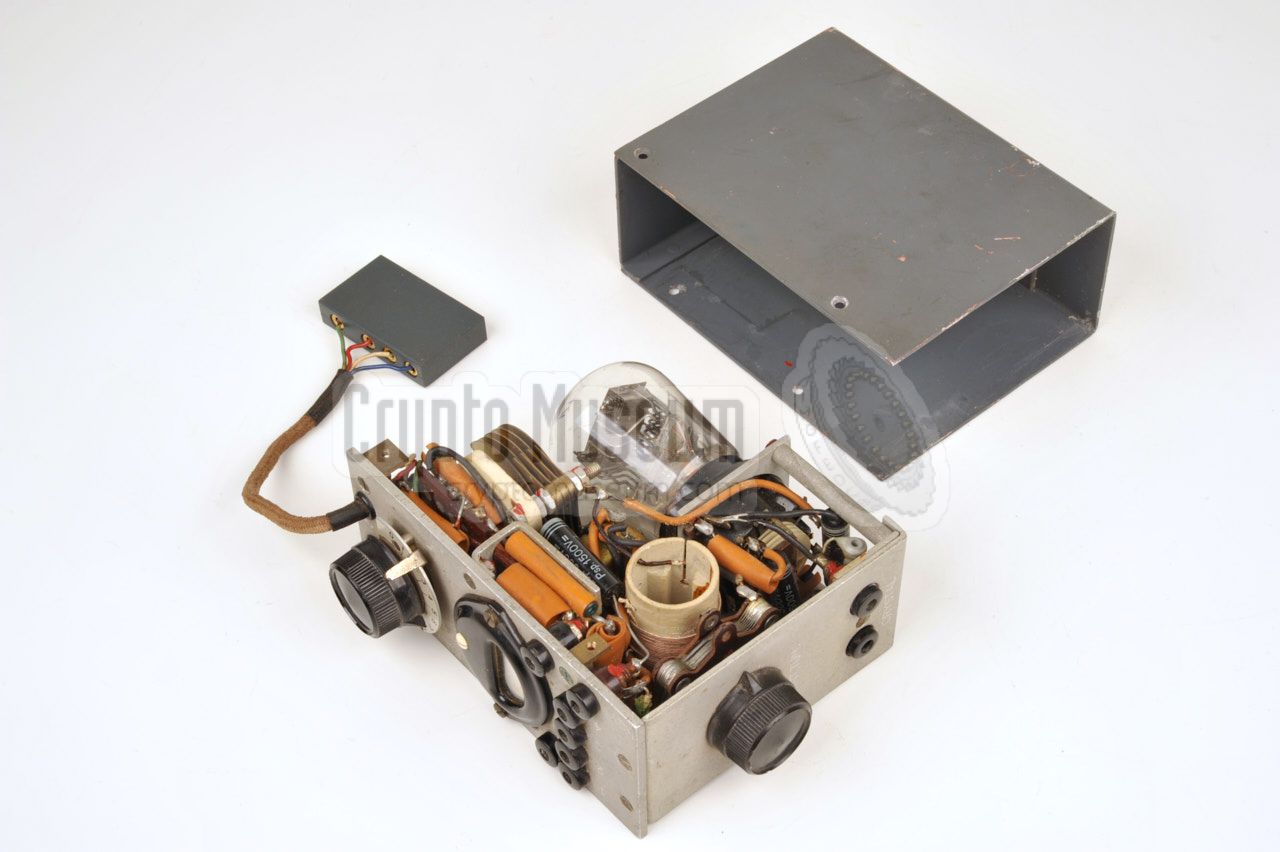
The receiver is roughly twice the size of the transmitter. It measures
17 x 10 x 8.5 cm and weighs ~ 1050 grams. Like the transmitter
it was available is several grey tones.
The receiver is powered by 90V DC (HT) and 3V DC (LT),
which are supplied via a short fixed cable with a rectangular 4-pin plug.
The pinout of this plus is identical to that of the transmitter.
➤ Look inside the receiver
|
|
|
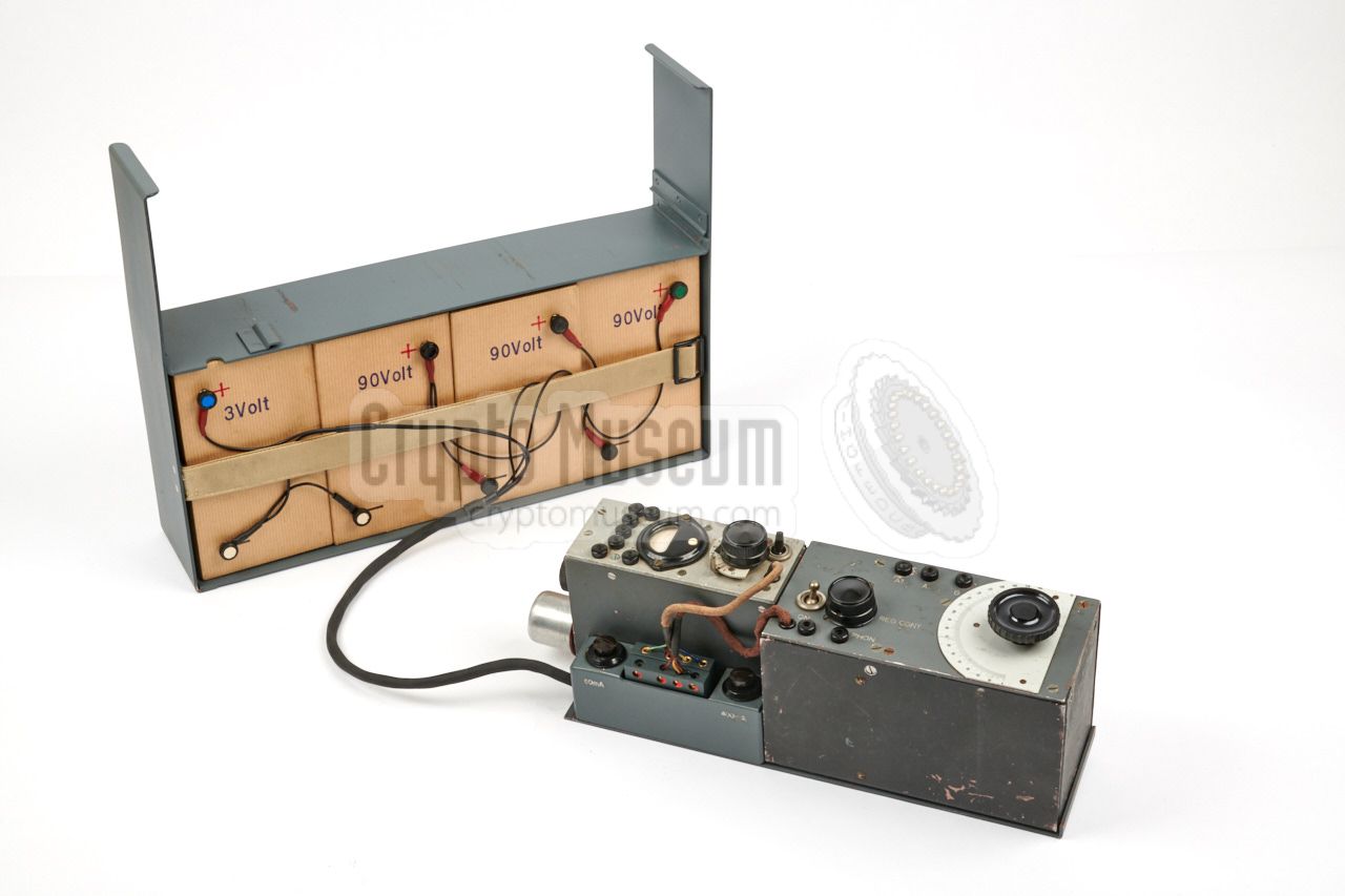
The exact types of batteries that were used with the SE 89/3 are currently
unknown. There are indications that a large 3V battery may have been used
in combination with a large 90/270V HT battery, or 3 smaller 90V HT batteries.
There are also indications however, that four equally sized batteries were used
as shown in the image on the right. The batteries shown here are reproductions
to visualize what they may have looked like. The can be filled with ordinary batteries so that the radio can be demonstrated.
|
|
|
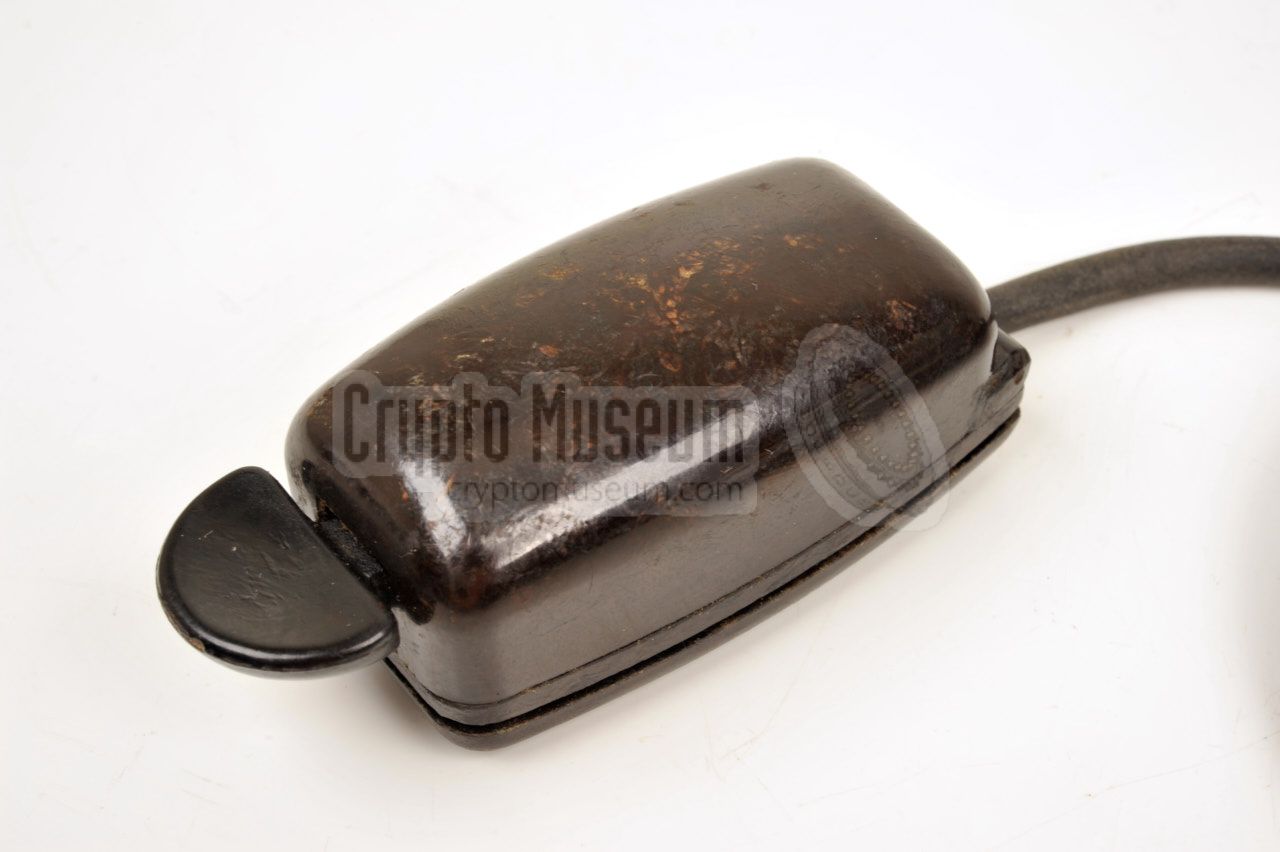
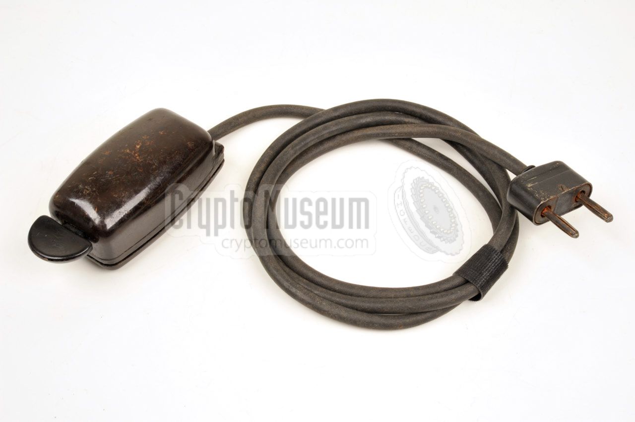
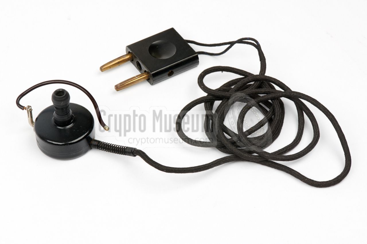
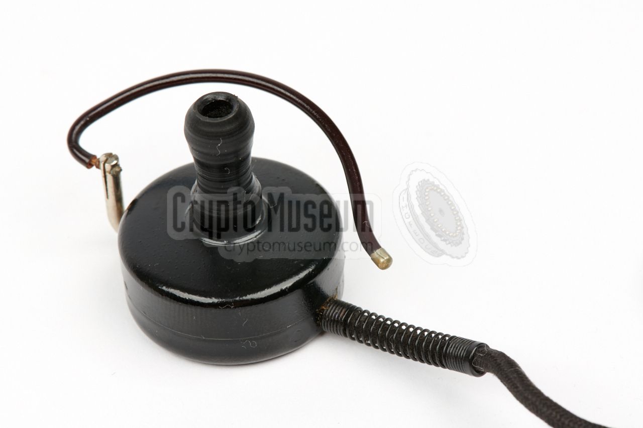
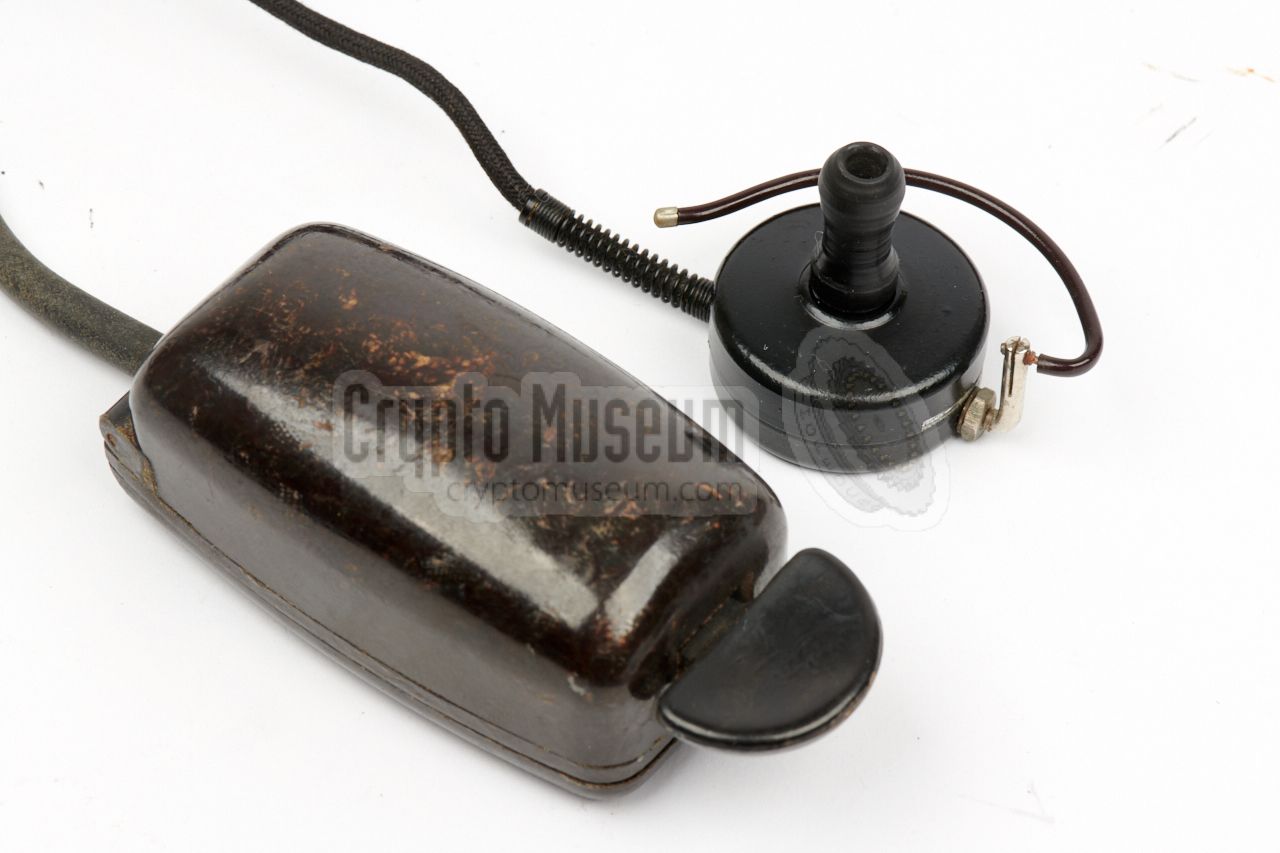
Virtually any type of morse key can be connected to the two banana sockets
at the bottom left of the transmitter. The SE-98/3 was normally supplied
with a small Bakelite® morse key that was nicknamed Maus (mouse).
The image shows a typical Maus with a 2-pin plug at the end of
its wire. Note the half-moon button at the front of the key, which
was often used for 'spy' equipment. Another type of Maus has a
circular button.
|
|
|
Although the receiver is suitable for connection of virtually any
type of high-impedant headphones, it was originally supplied with a small
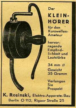
2000 Ω dynamic earphone, known as Ohrhörer or Kleinhörer, supplied
by K. Rosinski in Berlin.
This earphone had a diameter of 34 mm and weighted just 35 grams.
To accomodate the user's ear, it was supplied with three different olive-shaped
in-ear pieces. Two earphones were sometimes connected in series to obtain
4000 Ω. The image on the right shows an original Kleinhörer that was
made during WWII by Ideal. 1
|
|
|
-
After WWII, Ideal — based in Berlin (Germany) — became known as Blaupunkt.
|
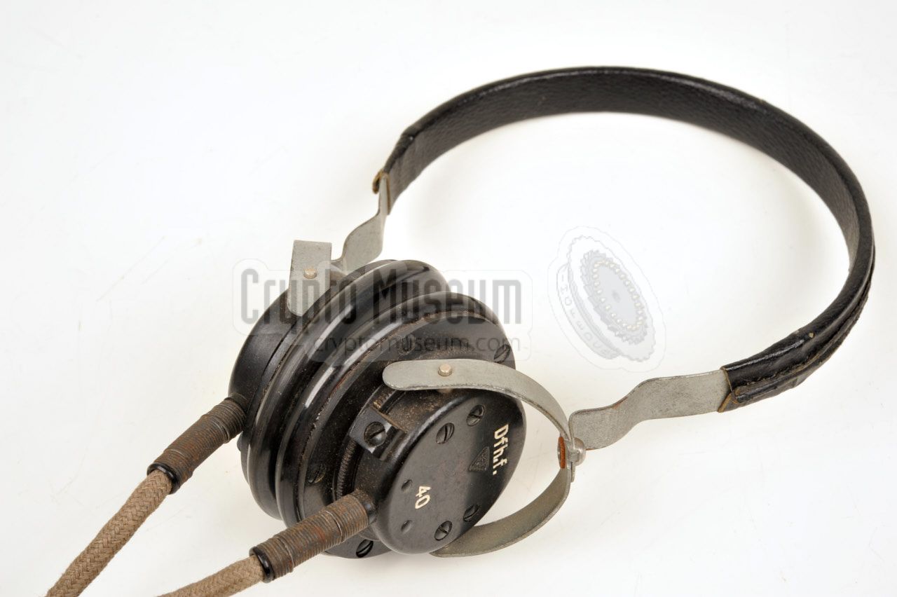
Alternatively, the SE-98/3 could also be used with a
common pair of high-impedance headphones,
that were also used with Wehrmacht equipment of the era.
The headphones shown here are the Dfh.f. 40.
The headset consists of two speakers with an impedance of 2000 Ω each.
Note that the headphones are connected in series with the anode of the
DL11 AF amplifier valve, and carry a +90V DC voltage.
This means that the wires should be properly isolated.
|
|
|
|
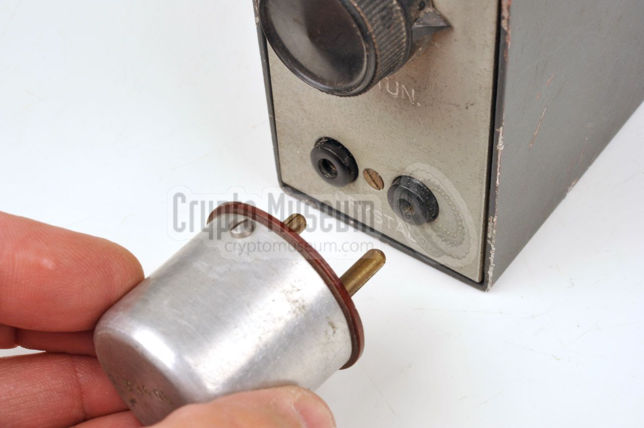
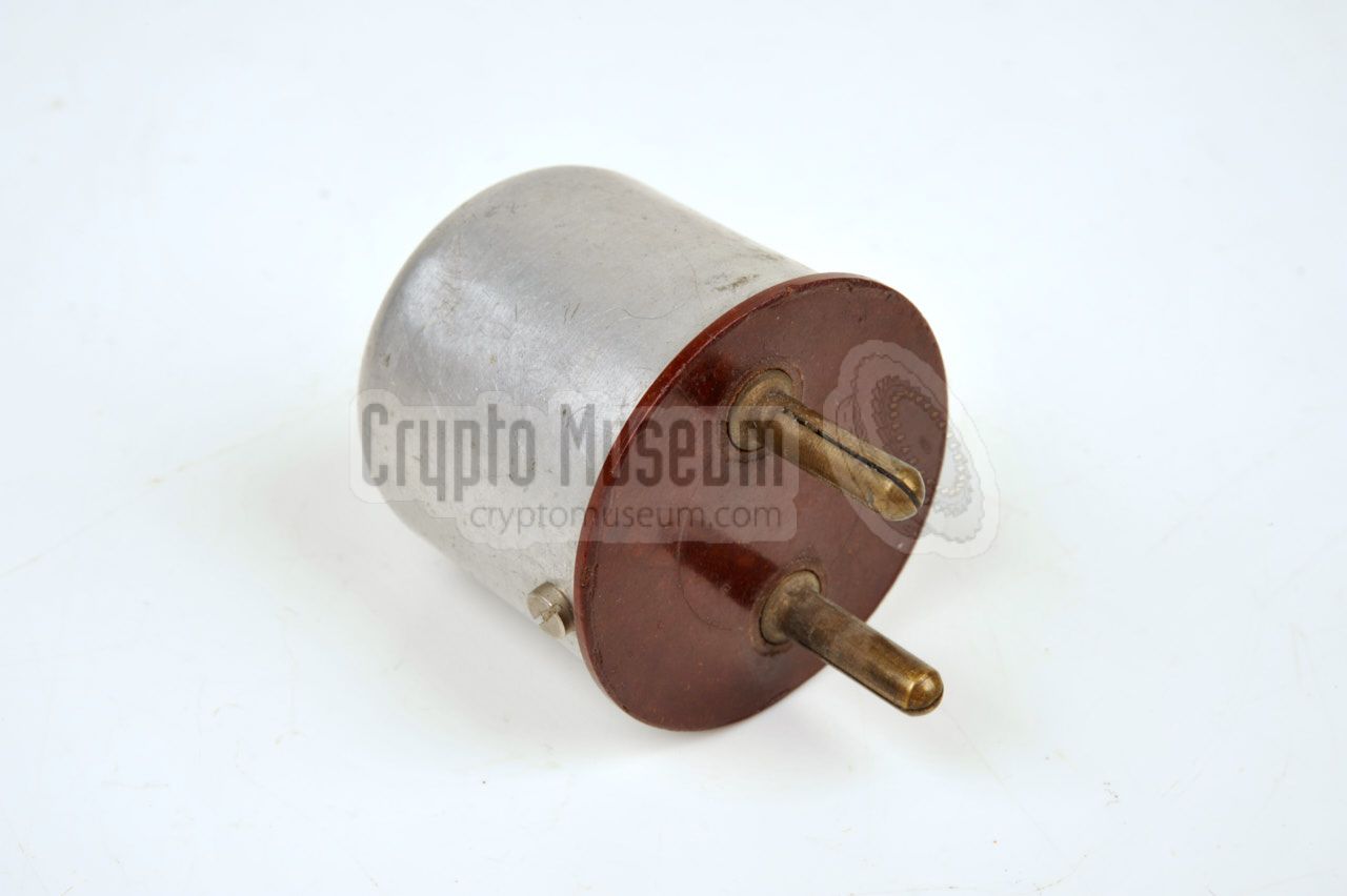
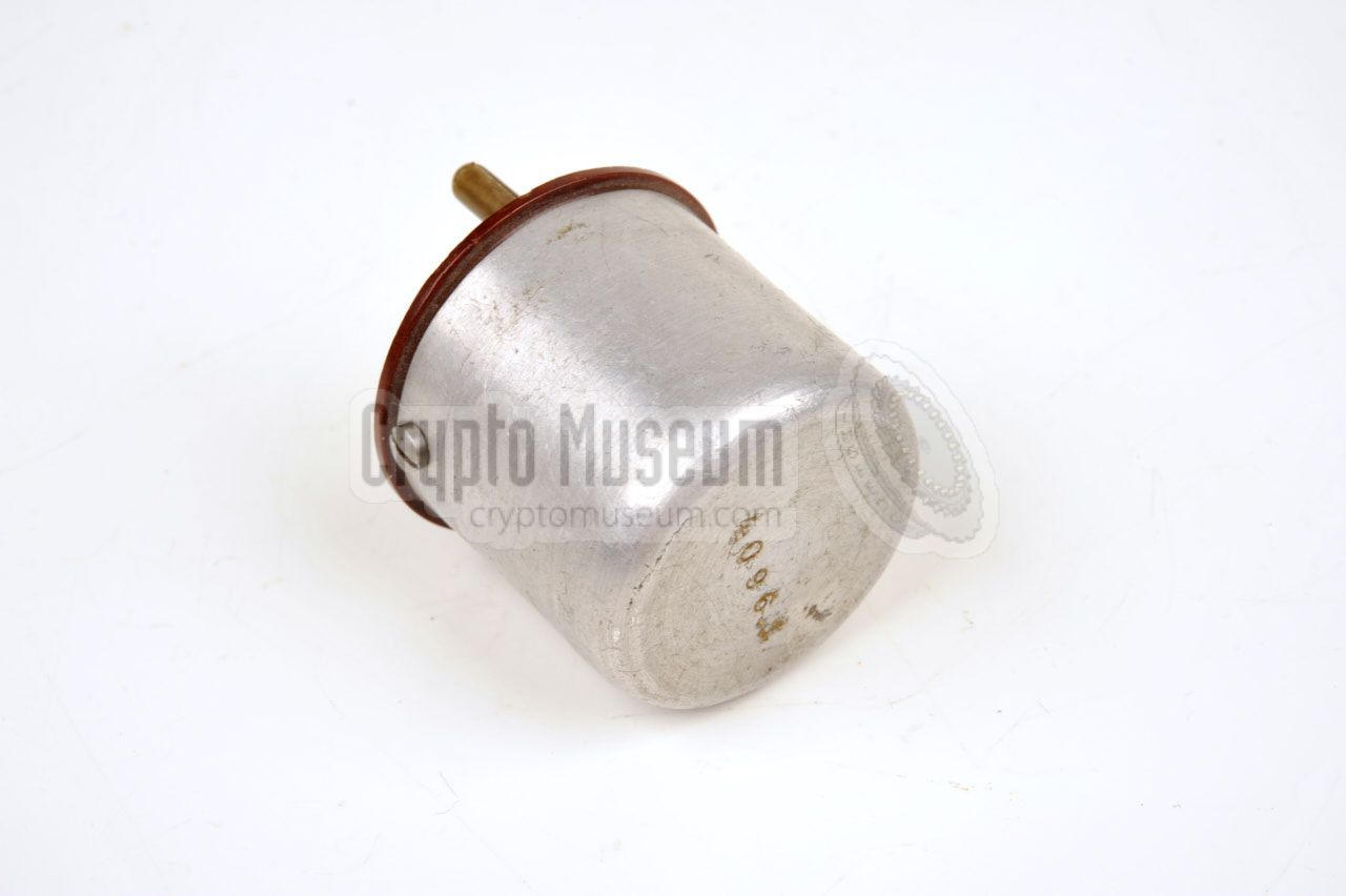
The SE-98/3 was typically used with a quartz crystal in a cylindrical
enclosure, such as the one shown in the image on the right.
The crystal should be inserted into the two banana sockets at the
bottom of the left side of the transmitter.
|
|
|
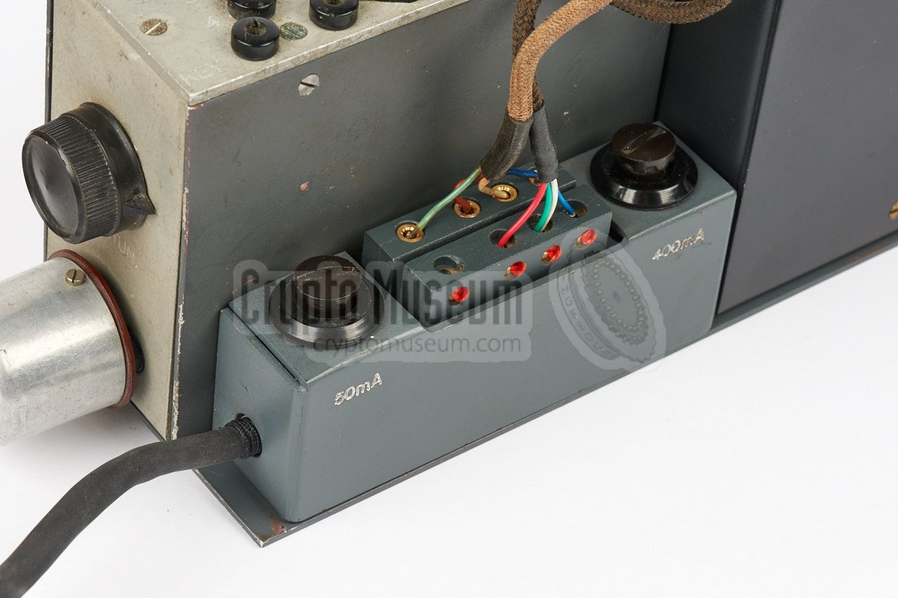
The SE-98/3 needs four batteries that are installed in the lower section
of the U-shaped metal frame, below transmitter and receiver. The batteries
are connected to the terminal block in front of the transmitter. One of the
batteries (the leftmost one) provides the 3V LT voltage for the filaments
of both devices. The 3V rail is protected by a 400mA fuse as shown in this
diagram:
The other three batteries each provide 90V and are connected in series
to obtain the +270V LT voltage for the transmitter. The +270V
rail is protected by a 50mA fuse. A tap after the first 90V battery
provides the +90V HT voltage for the receiver. The +90V rail is not
protected by a fuse.
Although both power sockets are wired identically, the +270V rail is not
used by the receiver.
|
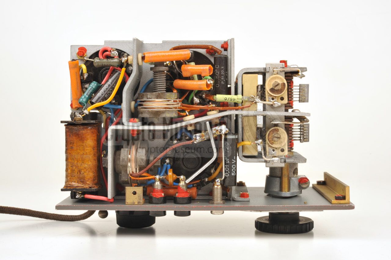
The transmitter consists of a metal frame that holds all components,
and a U-shaped metal case shell that is held in place by four recessed screws.
It has controls and connections on two of its sides. Sockets are present for
connection of the morse key, the crystal and the antenna.
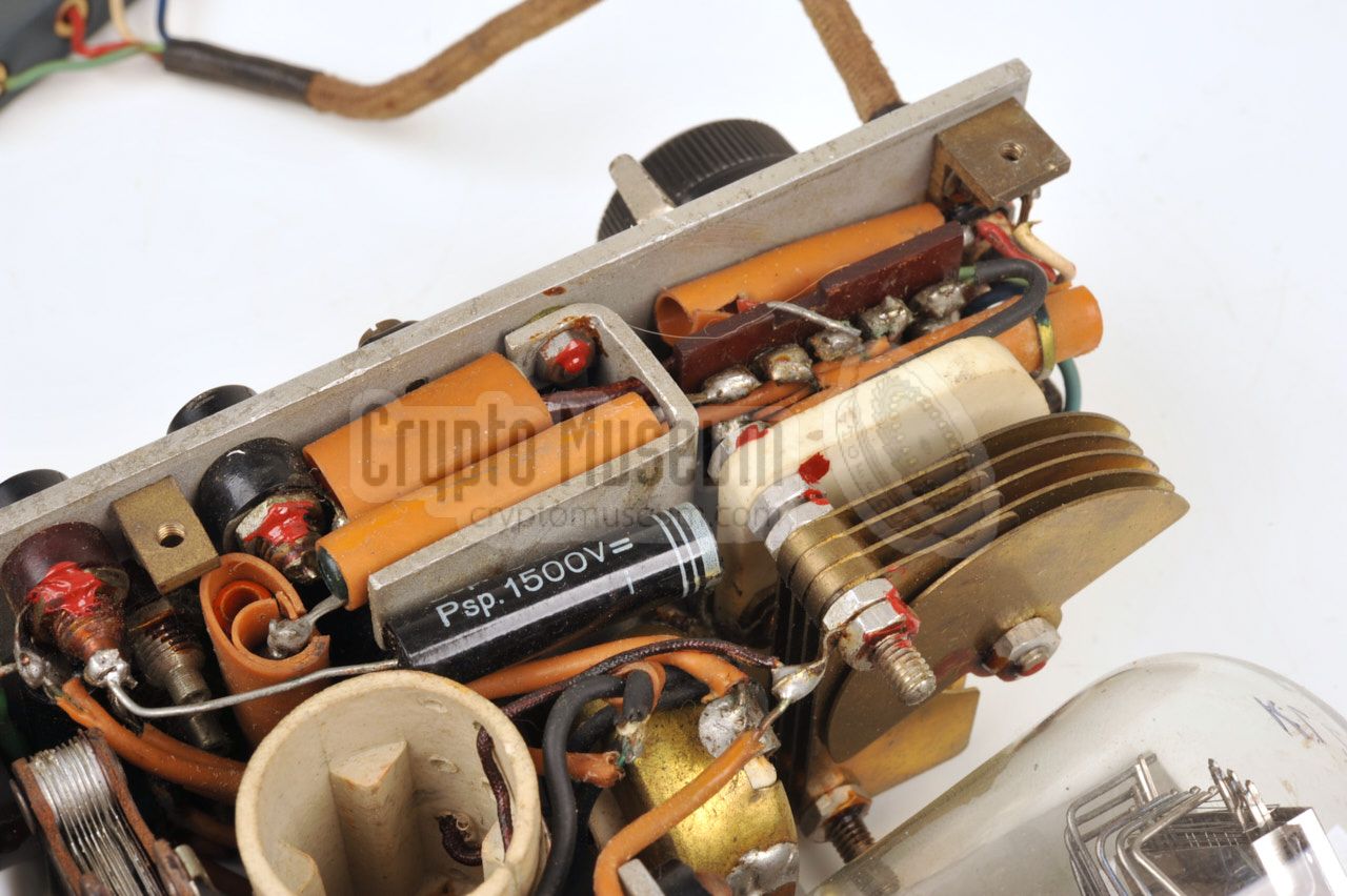
The image on the right shows the interior of the transmitter after the
metal case shell has been removed. The big KL2 valve is at the far corner.
The meter at the front panel is used for checking the RF output, as well as
the battery voltages. It is operated with a small lever below the meter.
|
|
|
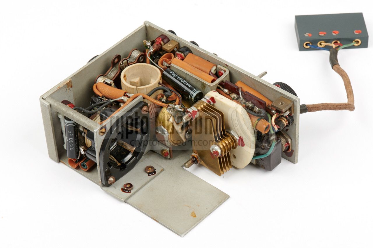
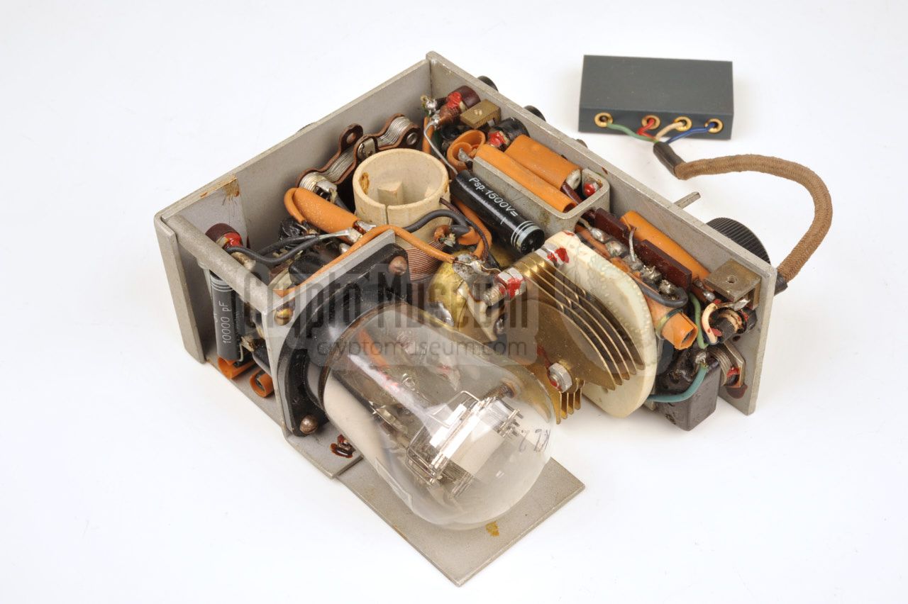
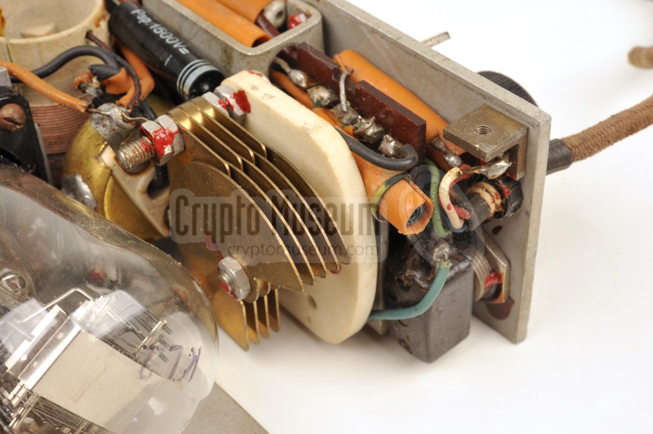
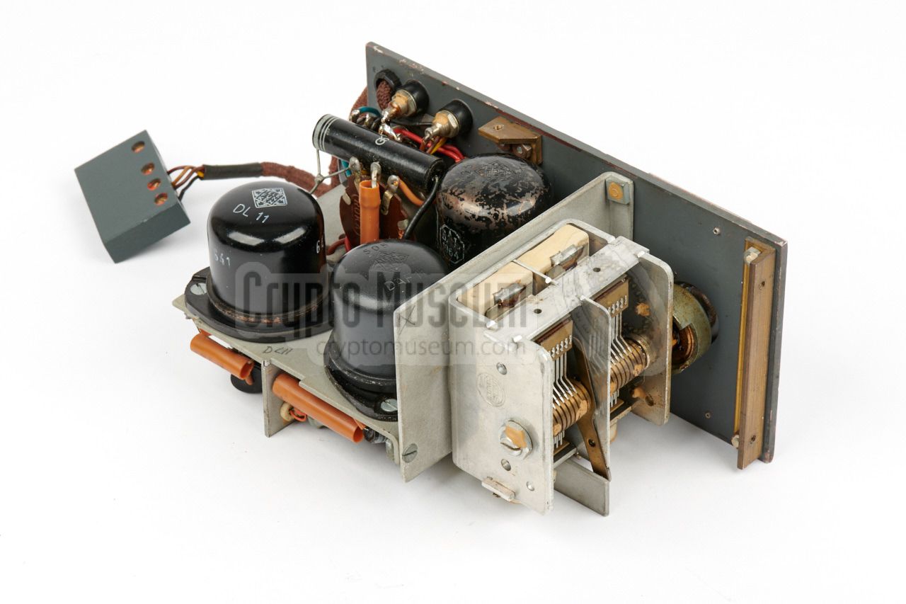
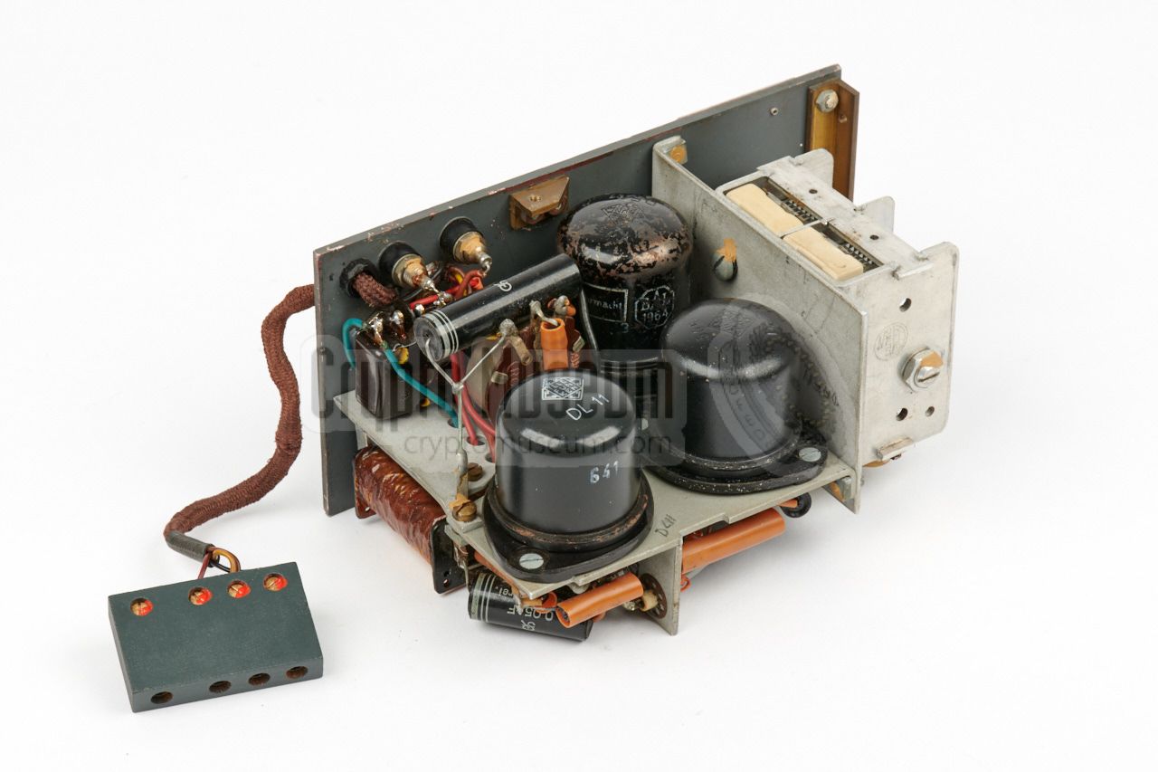
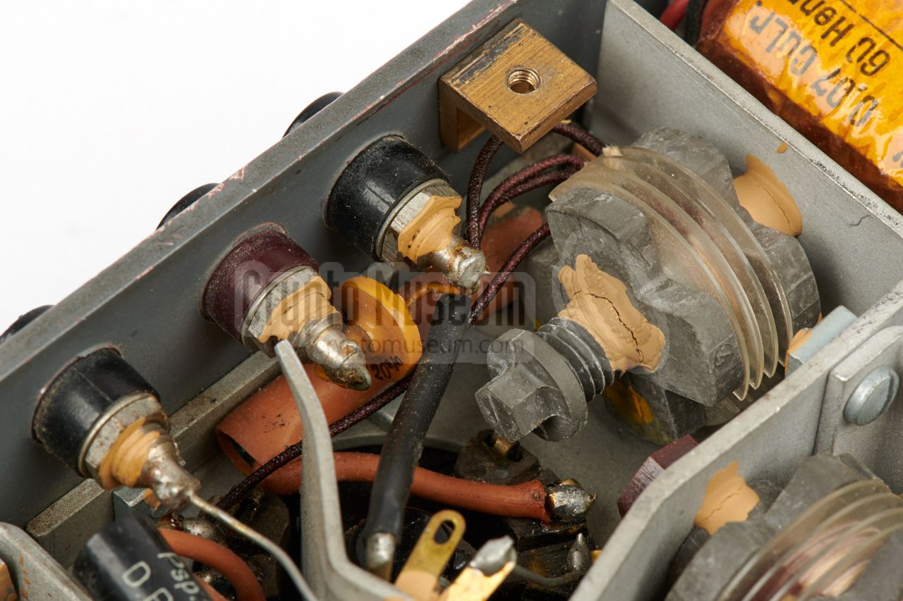
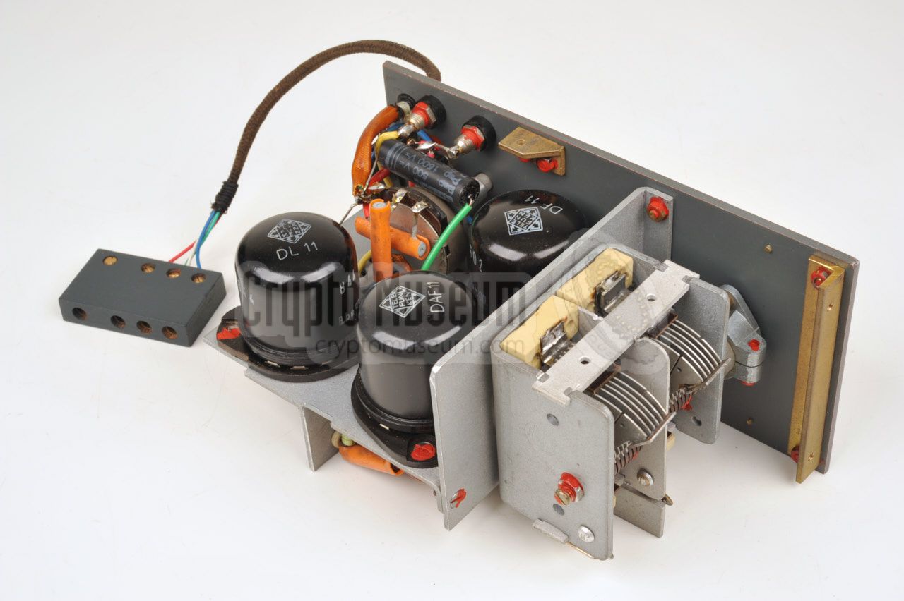
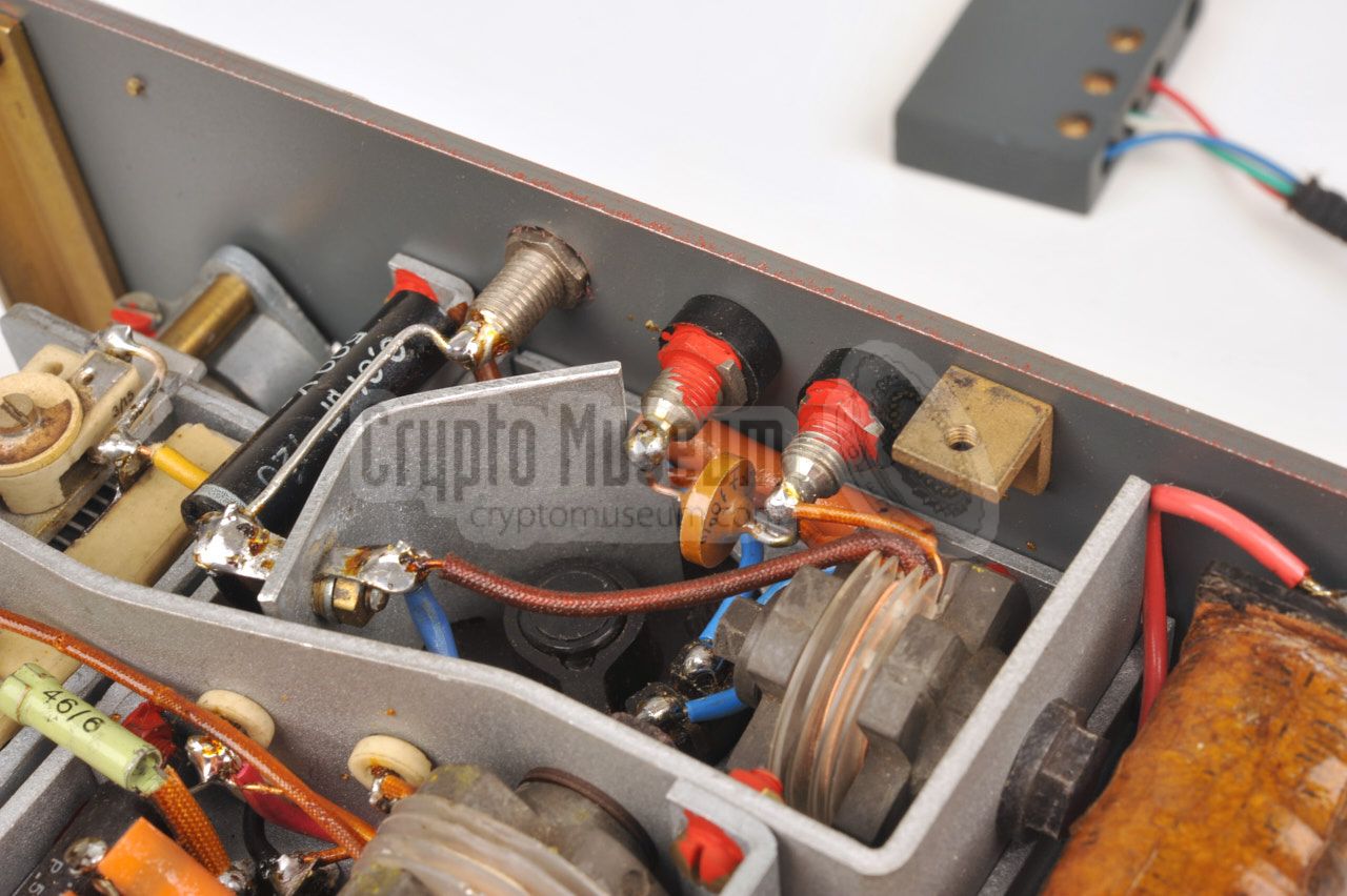
The interior of the receiver can be accessed by removing four screws from
the sides and taking off the case shell. This reveals a frame with all
components that is mounted to the front panel.
The image on the right shows the interior of the receiver after the case
shell has been removed, seen from the top rear side. Note that the valves
are mounted upside down. The circuit is built around three Telefunken
metal valves: a DF11 that is used as RF pre-amplifier, a DAF11 as the
oscillator/detector and finally a DL11 as the AF amplifier that delivers
audio to the headphones.
|
|
|
Below is the circuit diagram of the S-98/3 transmitter as it was published
by Rudolf Staritz many years ago [A]. This circuit diagram is based on the
original wartime drawings and is similar to the one that was published
in Wireless World in February 1941, which was based on a confiscated
S88/5 transmitter. The circuit is built around a single KL2 valve that
delivers an RF output of ~ 3 Watts. Transmission is controlled by a
morse key that directly switches the 270V anode voltage.
In this version, the crystal is connected in series between
the main coil and the g1 of the valve. By shorting the crystal, the device
can be used as a free-running oscillator.
It is likely that the design was changed at some point, as in the S-98/3 in
our collection (serial number 393) the crystal is connected to ground,
and there is no feedback from the tuned circuit, as a result of which it can
no longer be used as a free-running oscillator.
The circuit diagram of this variant is shown below.
At the bottom right is the meter. By default it is used for checking the
RF output of the device. This is done by picking up a small amount of RF
energy with the transformer (K) and rectifying it by means of a Siemens
Sirutor, which is in fact an array of diodes connected in series [3].
The voltages of the radio set can be checked by moving the metal lever
(located behind the PA Tuning knob) away from its default position.
From left to right it checks RF Power, +3V, +90V and +270V.
Note that +90V is not used by the transmitter. It is only required by the
receiver.
|
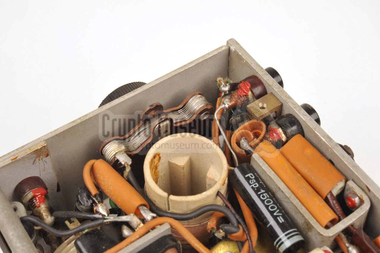
DIFFERENCES —
The drawing above shows the main oscillator coil, which is
different from the initial design. The coil is wound on a 25 mm
ceramic cylinder. The primary coil is made of 0.5 mm Cu and
has 17 windings. It is connected directly to the 270V, whilst the variable
(tuning) capacitor is connected to ground.
The secundary coil also has 17 windings, but is made of
slightly thinner 0.4 mm Cu. It has taps at three points, as specified in the
circuit diagram above. Also note that one side of the crystal is connected
to ground, and that the circuit oscillates by the virtue of the parasitic
capacitance between the cathode (k) and the grid (g1). The choke coil (Dr) is
connected in series with the cathode of the KL2 rather than in the
anode rail.
The later – improved – design is much more stable and puts far less load on
te crystal, at the price of loosing the ability to use the transmitter in
free-running mode.
The circuit diagram of the E-98 receiver is given below, which is actually
a miniaturised version of the E-97 receiver. Power is applied to the circuit
via the 4-pin connector at the bottom right, of which the +270V terminal is
not used. Both the +3V and the +90V rail are passed via the ON/OFF switch.
The +3V LT voltage is supplied to the filament of the DF11 via a 50 Ohms
resistor. Note that the filaments of the other two valves (the DAF11 and the
DL11) are connected in series.
The receive antenna is not shared with the transmitter. Instead a separate
wire antenna and a suitable counterpoise should be connected to the ANT and
GND terminals at the left. A high-impedant pair of headphones should be
connected to the headphones terminals at the top right. Note that the headphones
are connected in series with the anode line of the DL11 valve, which means
that the wires carry a voltage of +90V. Ensure that these wires are properly
insulated.
|
DIFFERENCES —
Please note that various circuit diagrams of the E-98 receiver are in
circulation, all of which are claimed to be 'originals' and all of which
are different. For example: the extra antenna input (A/A1) is not always
shown and the top half of the oscillator coil (L2) is sometimes drawn at
a different location. The E-98 was built in fairly large quantities — the one shown
here has serial number 500 — and it is possible that the circuit was modified
over time. The diagram above was taken from the original receiver in our
collection and closely matches one of the diagrams published by Rudolf Staritz,
which were based on wartime drawings [B].
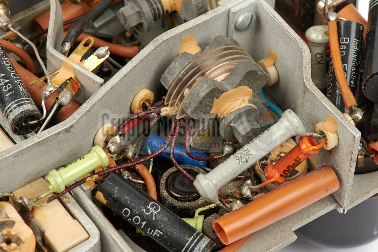
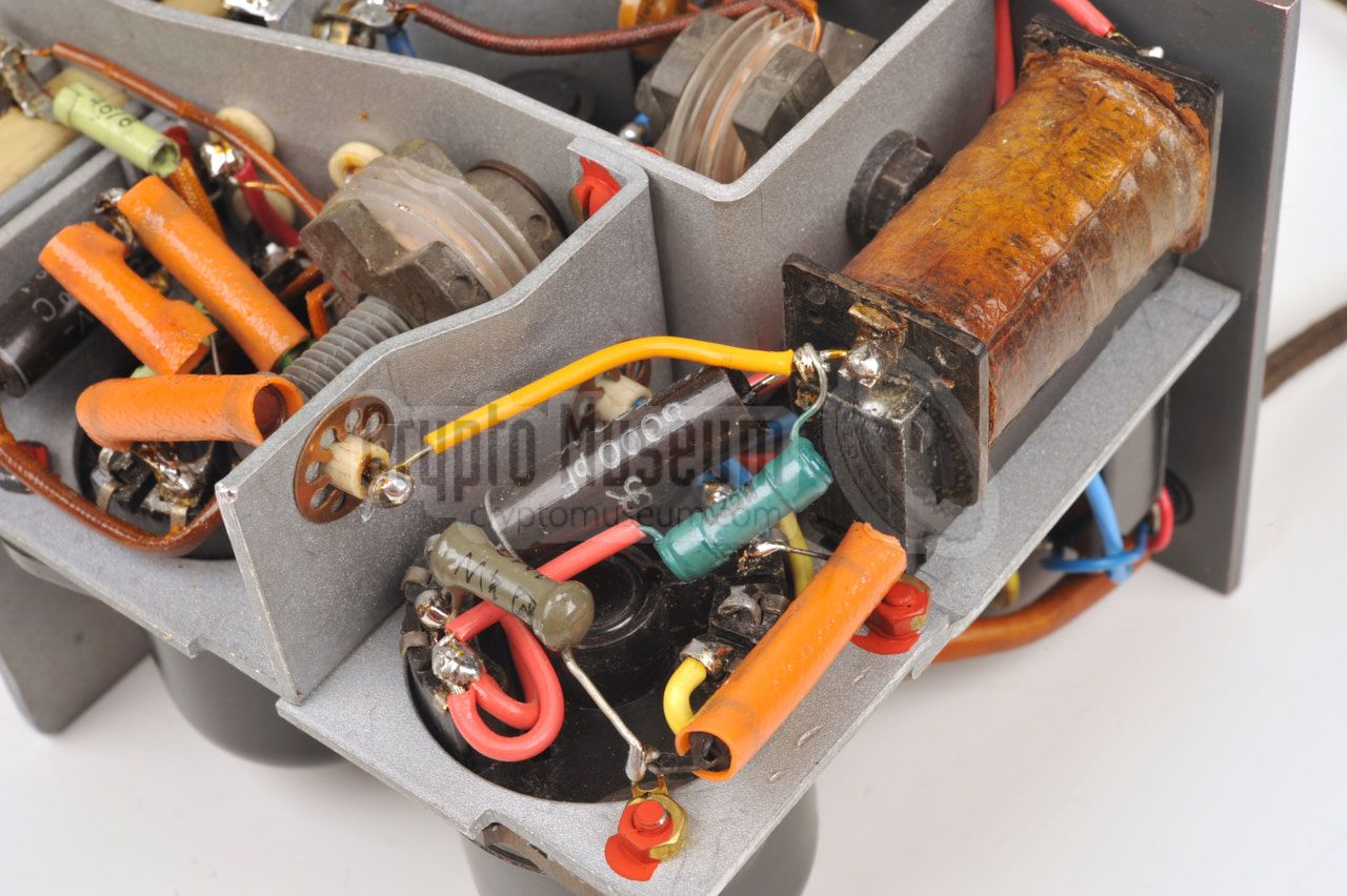
Note that the 20pF capacitor in the anode circuit of the detector valve (DAF11)
is actually a trimmer. It is located close to the solder contacts of the DAF11
socket and is just visible in the right half of this image.
|
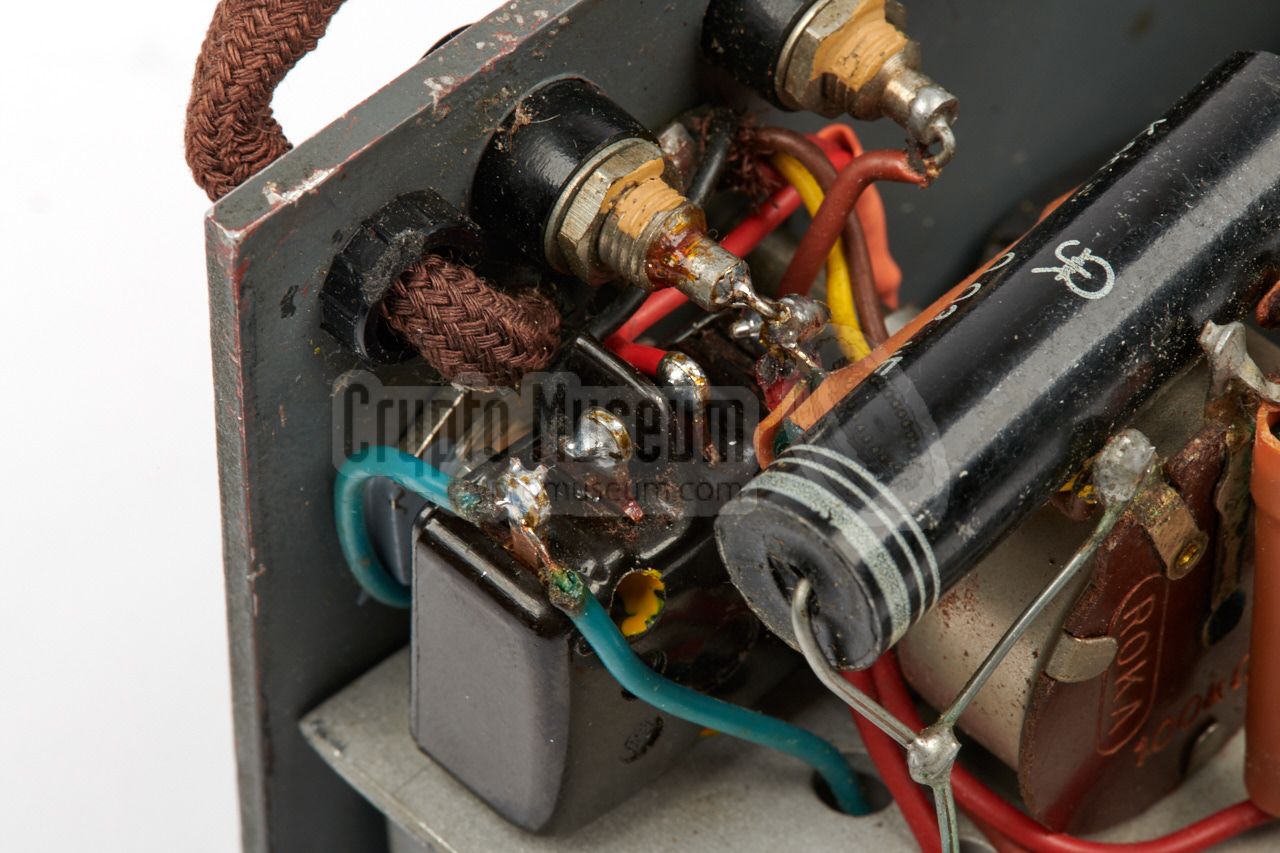
When we obtained the receiver, it was in non-working condition. After a brief
inspection, the main ON/OFF switch was identified as the root cause of the
problem. After many years of service and storage, the contacts inside the
switch had probably been burned-in or were corroded.
|
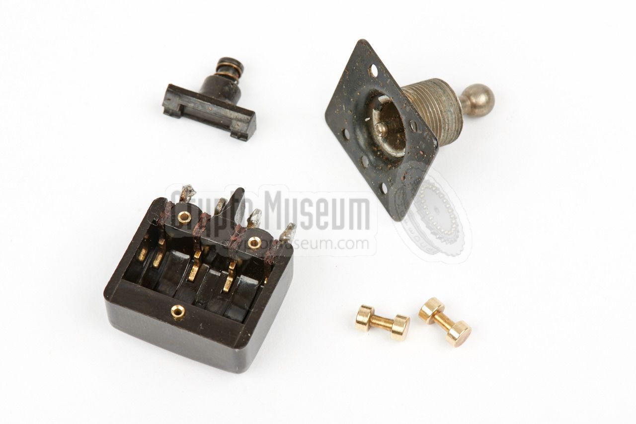
Although the switch is a non-serviceable part – it is secured with hollow rivets –
it was decided to attempt to repair it, as an identical replacement switch was
not available. The three hollow rivets were carefully drilled out, so that the
upper part could be removed from the bakelite base. It was found that the
contacts had indeed burned in.
After cleaning the four fixed base contacts, and the two dumbbell-shaped movable
contacts, the switch was reassembled, using 2 mm
screws to replace the rivets and a drop of contemporary locking varnish to keep them
in place over time.
|
|
|
|
The image above shows the disassembled double-pole power switch, with its
internal contacts cleaned. After carefully re-fitting the switch and restoring
its wiring, the radio could be tested. It worked straight away, but exhibited
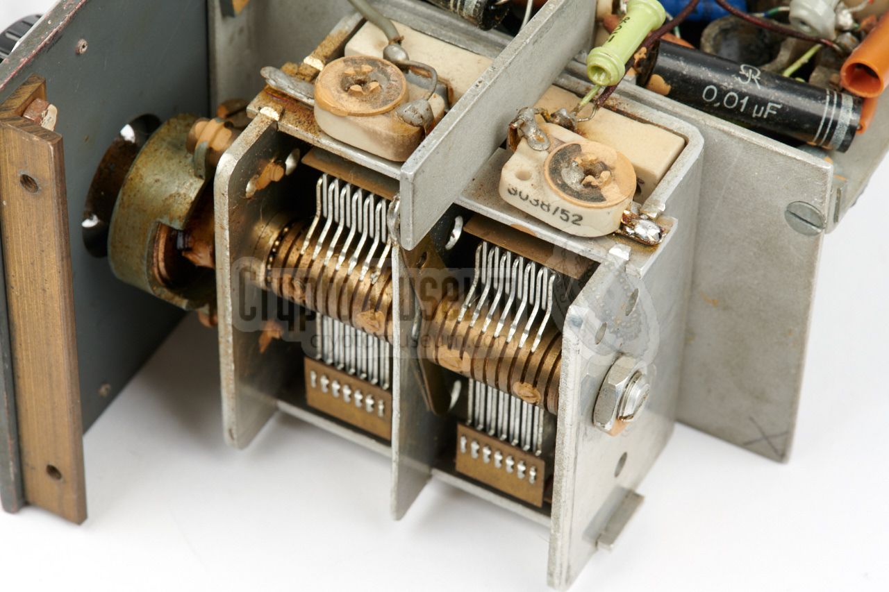
'gun shots' when the main tuning capacitor was turned.
|
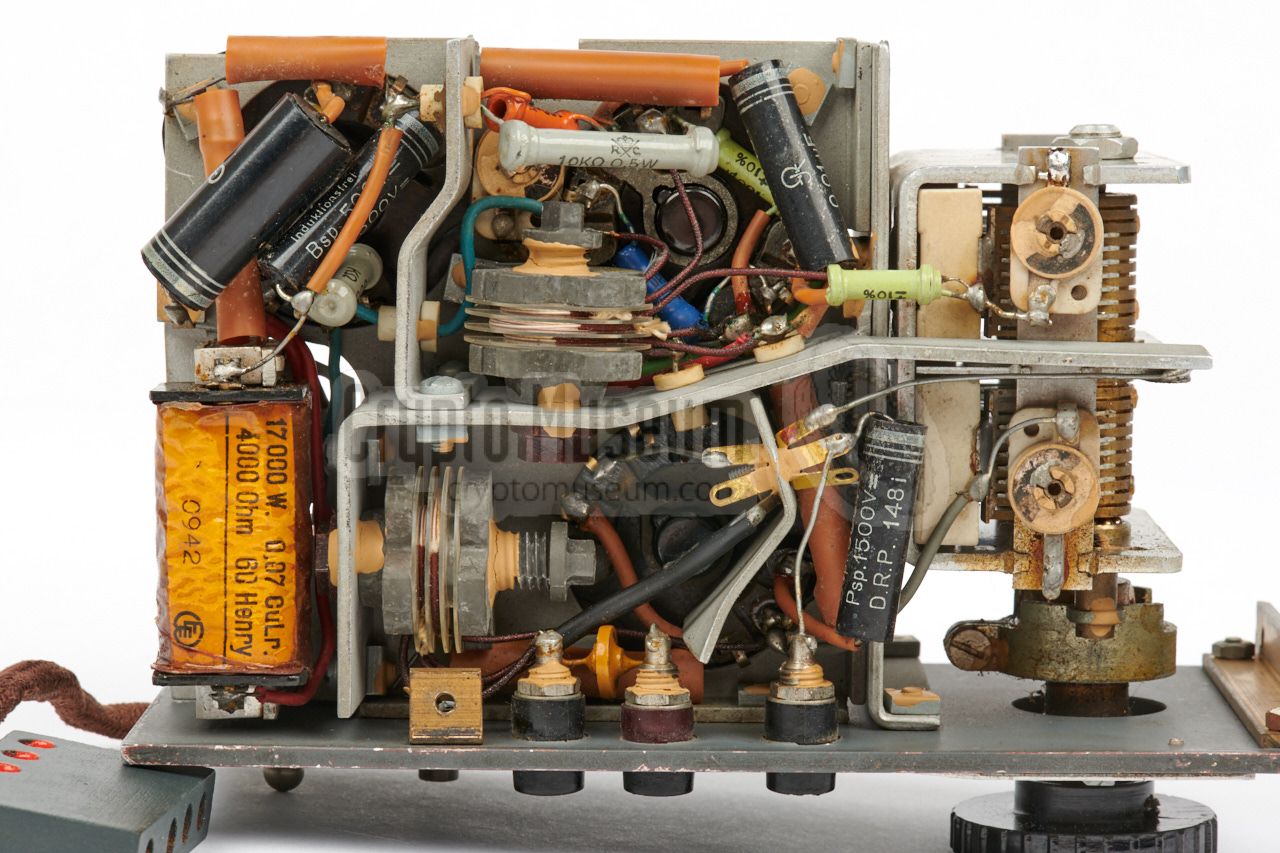
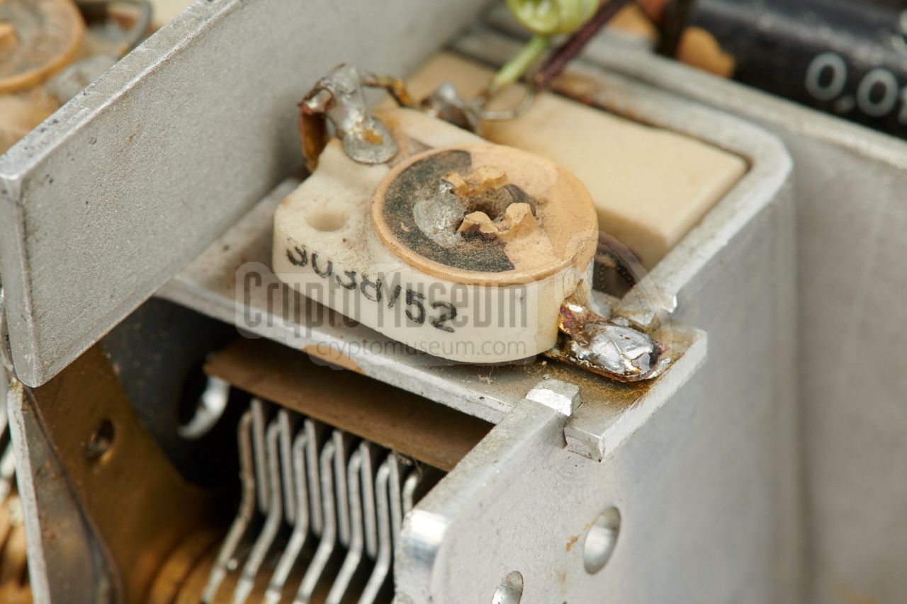
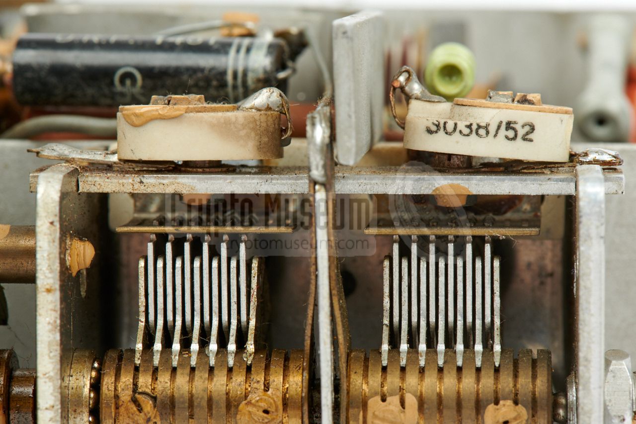
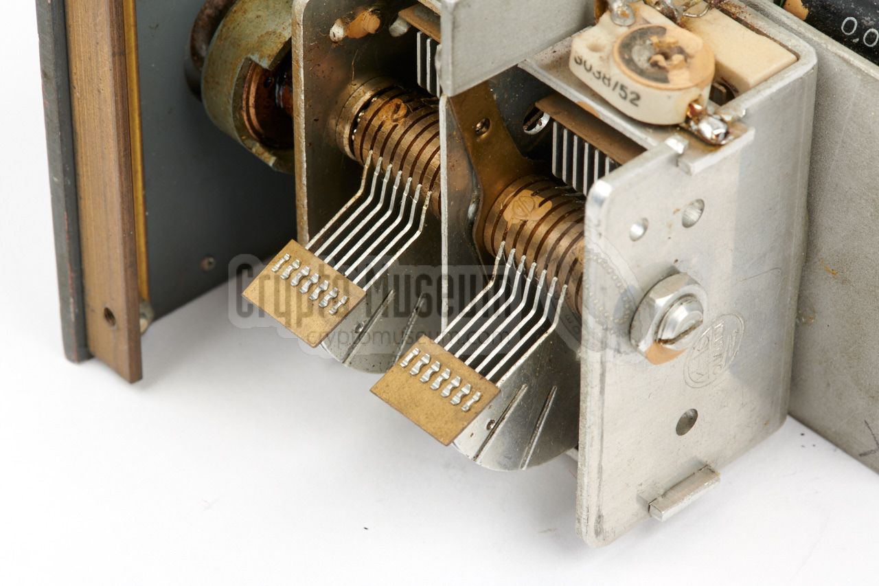
Further investigation showed that this effect was caused by four independent
problems. The first one was easily fixed. One side of the rightmost trimmer
on top of the tuning capacitor had a broken contact. After soldering it back
in place, the receiver suddenly became much quieter.
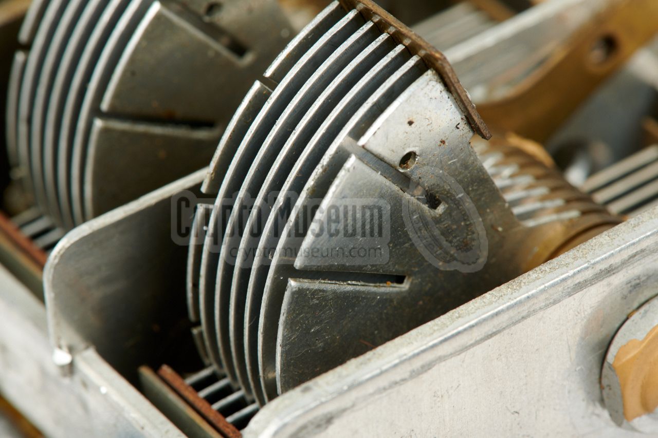
A second problem was caused by one of the blades of the rightmost tuning
capacitor. It was slightly deformed – probably as a result from falling down –
and touched the adjacent blade after turning the capacitor approx. 130 degrees in.
It was fixed with a flat dental modelling knife.
|
|
|
The last problems showed up intermittently and did not seem to be related
to the position of the capacitor. It was partly caused by metal dust which
had accumulated between the blades over time, and partly by the main axle
which was not always properly connected to ground. Thorough cleaning of the
capacitor and applying a drop of cleaning oil to the bearing, fixed both
problems.
So far, the following restorations have been carried out:
|
- Transmitter: glass of KL2 valve glued in place
- Circuit diagram taken from real device
- Receiver: exterior cleaned
- Power switch repaired and refitted
- Trimming capacitor soldered in place
- Tuning capacitor short circuit between the blades fixed
- Tuning capacitor contact problem fixed
|
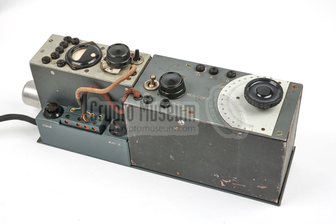
The transmitter and receiver are eached powered via the terminal block
at the front edge of the radio, just in front of the transmitter. There
are two 4-pin male sockets that are wired identically. The sockets provide
the +3V LT voltage for the filaments, and the +90V and +270V HT voltages
for the anodes of the valves. Note that the receiver does not require
+270V. The power sockets are wired as follows, when looking into the male
sockets from the front of the device:
Also note that 90V is only required for the receiver, but that this voltage
should be supplied to the transmitter as well, so that its meter can be
used to monitor this voltage rail.
Finding a suitable connector for this socket can be very difficult, as they
were probably purpose-built at the time. As a gap-fill solution it is
possible to use female banana plugs and place them over the pins in the
socket. The best solution however, would be to make a replica from era-correct
materials. Below are the dimensions of the plug (in mm). The body
is made of pertinax.
➤ Download drawing as PDF
|
Below is the pinout of the socket of the KL2 valve, as seen from the bottom
(i.e. the solder side of the socket). Note that the unused pins (here shown in
grey) are used as a mounting post for other parts and wires.
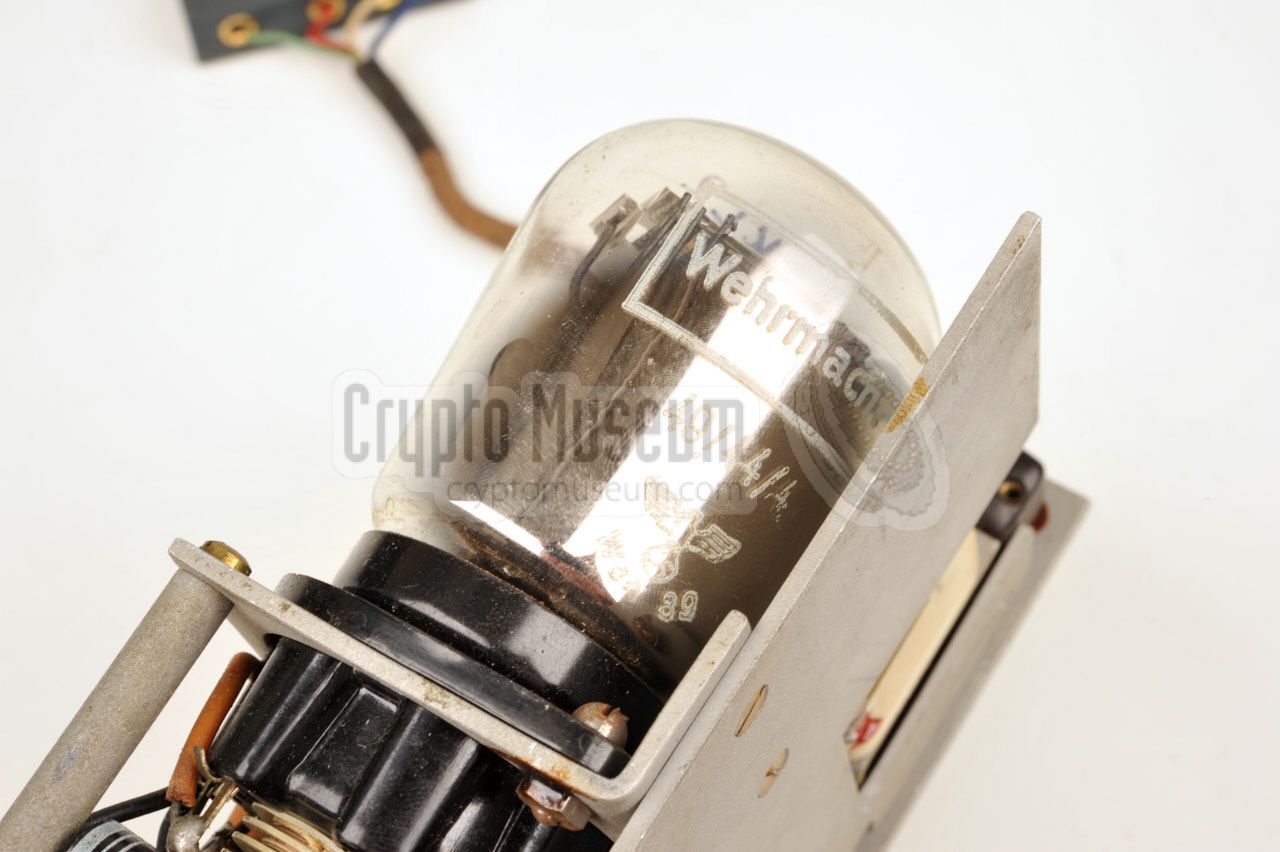
This valve was manufactured during WWII especially for the German Wehrmacht by
companies like Telefunken, Philips and Tungsram. In the latter case, the part
number is TKL2.
➤ KL2 (TKL2) datasheet
|
The receiver is built with three different valves — DF11, DAF11 and DL11 —
each of which has a metal enclosure (German: Stahlröhre) with a typical 8-pin
steel-valve socket (3 + 5 pins). Note that these valves are available in two different heights,
both of which are allowed in the E-98 receiver.
The diagram below shows the pinout of each valve, as seen from the bottom.
➤ DF11 datasheet
➤ DAF11 datasheet
➤ DL11 datasheet
|
Model SE 98/3 Case Metal container (optionally in leather suitcase) Dimensions 38.5 x 28 x 10 cm Weight 4000 grams Dimensions 13 x 10 x 5 cm Weight 750 grams
|
Model E 98 Frequency 2.1 - 8.2 MHz Mode AM R/T and CW (morse) Oscillator VFO Valves DF11, DAF11, DL11 Dimensions 17 x 10 x 8.5 cm Weight 1050 grams
|
Model S 98/3 Frequency 3 - 8 MHz Output 3 Watt Mode CW (A1, morse) Oscillator Quartz crystal operated Valve KL2
|
|


![Original photograph made by Rudolf Staritz in the 1980s [4].](img/rosinski_thumb.jpg "image # rosinski_large.jpg")

![Original photograph made by Rudolf Staritz in the 1980s [4].](img/rosinski_large.jpg)