|
|
|
|
|

|
|
USSR Cold War Burst KGB GRU R-394K → ← R-354
The R-353 is one of the most beautiful and most sophisticated
valve-based spy radio sets of the Cold War.
It is completely self-contained and has a
removable power supply unit
that is suitable for virtually any mains voltage in the world.
Contrary to many other Cold War era radios, the R-353 is a true
spy radio set,
that was used by Soviet and other Warsaw Pact
spies and agents, to
send messages to the countries behind the Iron Curtain.
Therefore, most of the R-353 sets have their markings and controls
in English, as that would reduce the risk of being exposed.
|
|
|
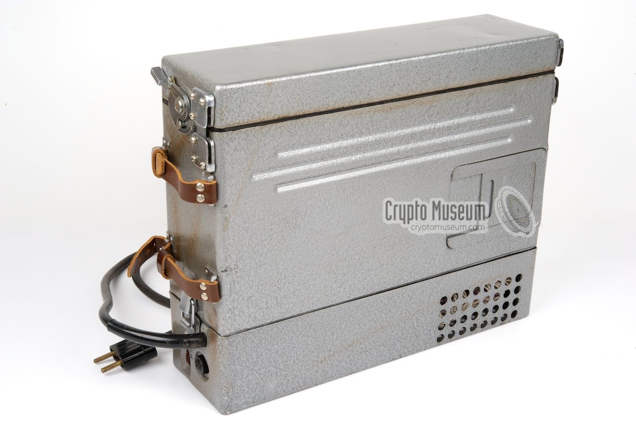
Like most Russian equipment of the era, the case is finished with hammer
paint. Two colours are known to have been used for this: grey (most common)
and green/blue Hammerite. The purpose of the different colours is unknown,
but might be related to the end-user or the factory. In practice the colours
were often mixed, so that a grey transceiver might contain green parts.
The R-353 was introduced in 1969 and was designed to replace earlier
spy radio sets like the
R-350 and
the R-354.
It is currently unknown how many R-353 radios were produced.
In the early 1980s, the R-353 was gradually phased out in favour of the
R-394K,
an analogue-PLL-driven radio set that had a similar tape-based
burst encoder. The R-394K was followed by the short-lived
R-394K Mark II,
that had a digital burst encoder, and eventually by the
all-digital R-394KM.
|
-
Russian: Хáрьков (Kharkov),
Ukrainian: Хáркiв (Kharkiv).
|
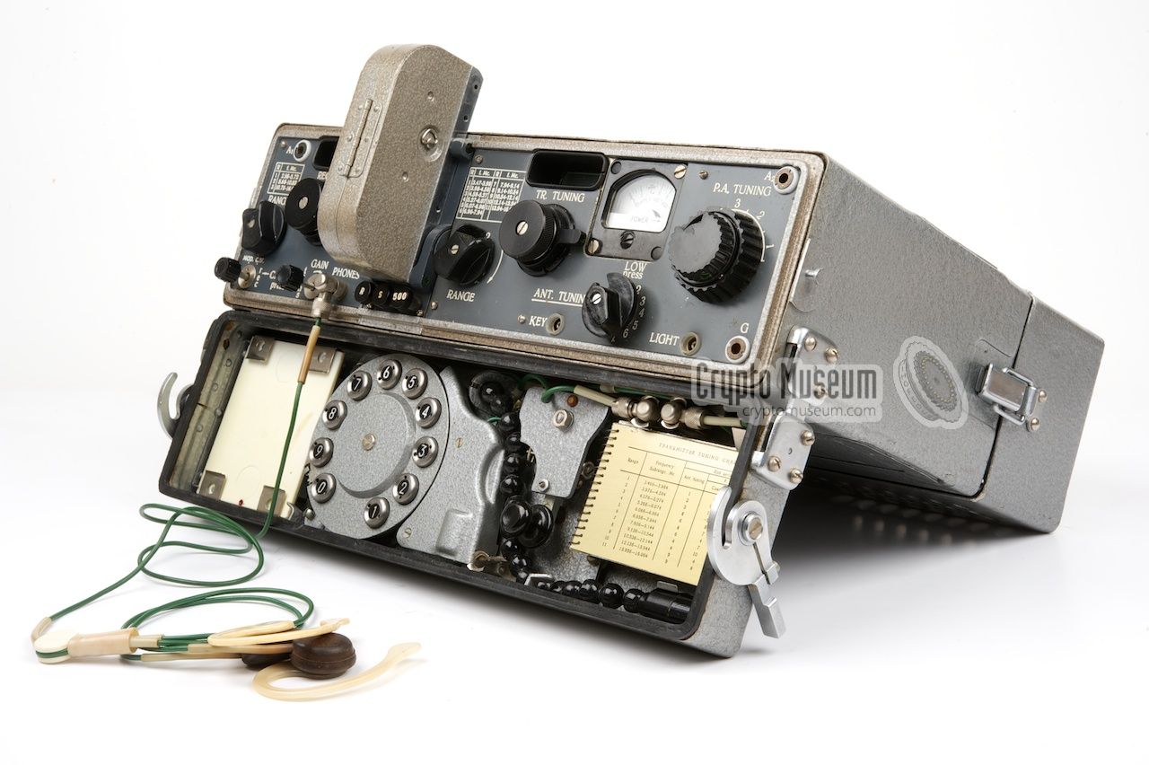
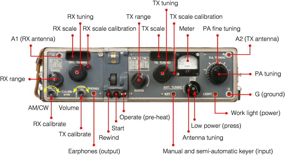
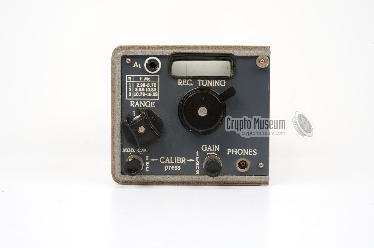
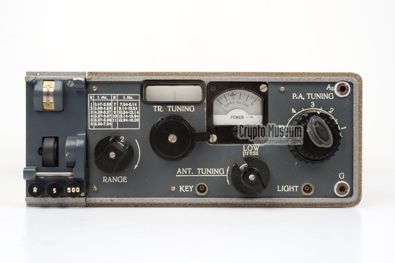
The R-353 is a Short Wave (SW) transceiver, suitable for frequencies
between 3 MHz and 16 MHz divided over 3 (RX) and 11 (TX) ranges.
All controls and
connections are at the front panel,
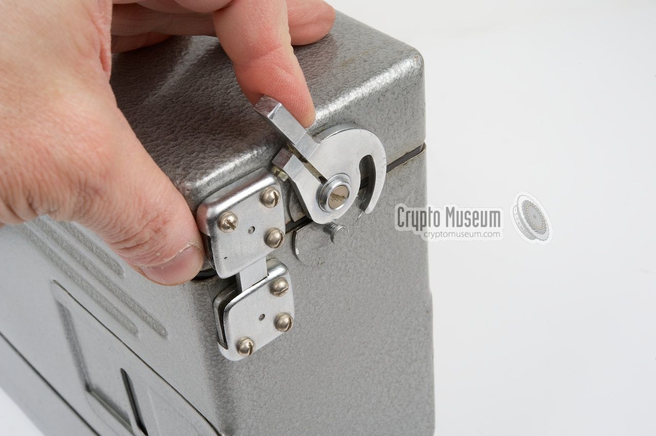
which can be revealed by opening
the top lid by releasing the two locks
at the left and right side.
After folding the top lid away from the front panel, it can be
locked in place,
allowing the transceiver to be tilted somewhat, so that the controls
are easily accessible. The R-353 consists of three parts:
At the left is the receiver. It has three frequency ranges and a
projection scale for the frequency readout.
At the right is the transmitter. It is about
twice as wide as the receiver and also has a projection frequency scale.
In between the receiver and the transmitter is the keyer,
or burst transmitter,
which allows a pre-recorded metal tape cassette to be played back at
high speed.
The image above shows the location of the various controls and connections.
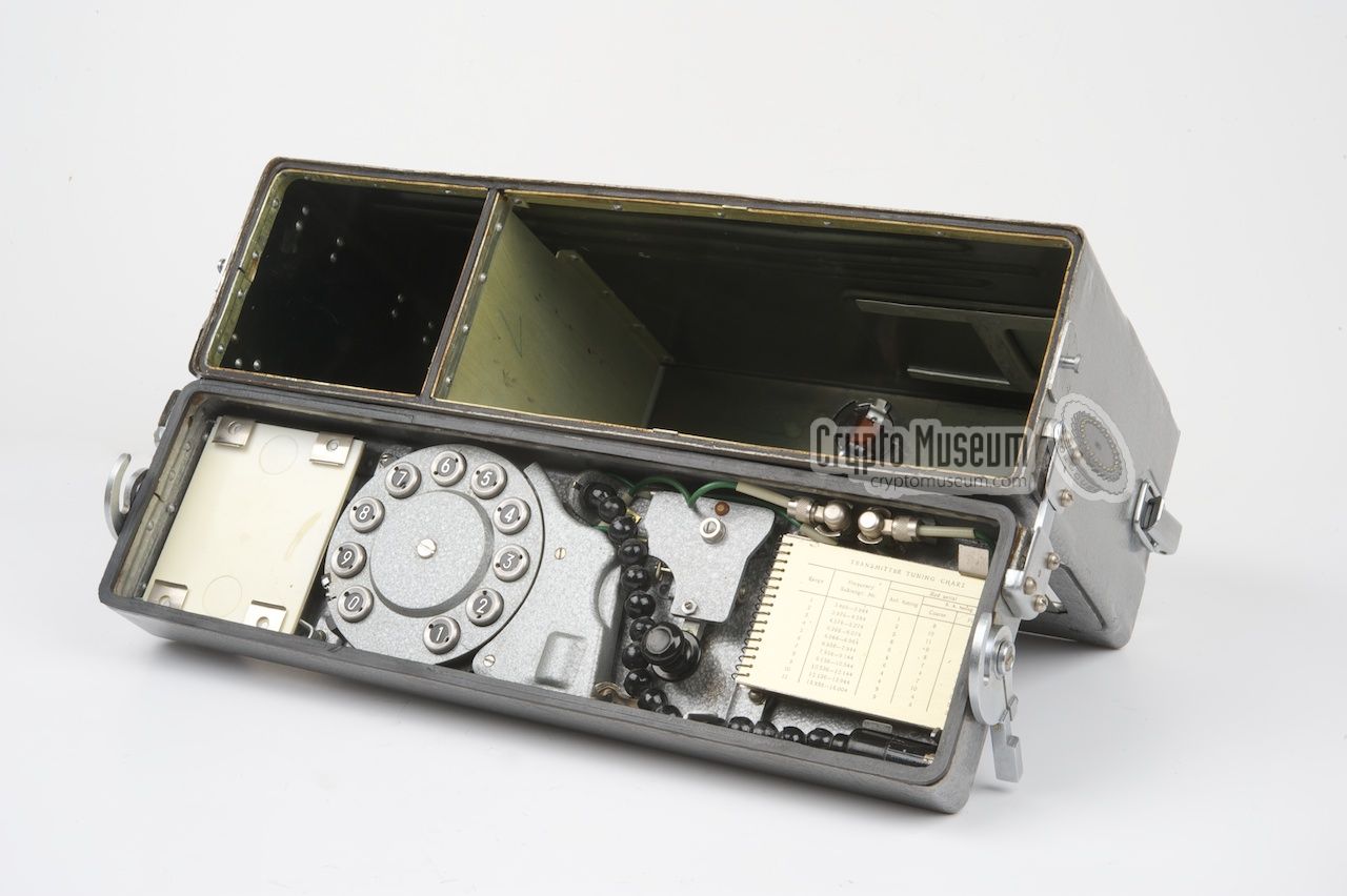
The bottom half is the interior of the top lid. It contains
a morse key,
a semi-automatic morse dial,
a tuning chart,
a pair of earphones
and a set of spare lamps and fuses (hidden under the
earphones). Also hidden in the top lid is a
flexible work light that can be
used to read the controls and instruction when using the device in the dark.
Before they can be used, the earphones, the morse key and the work light
must be connected to the front panel of the transceiver by means of
three small plugs.
➤ Operating instructions
|
|
Below are some audio samples of the R-353, recorded by collector
Karsten Hansky in Germany in July 2017 [3].
The radio was connected to a dummy load and an
ELAD FDM-S1 was used to receive and record the signal. Further sound
processing was done with Audacity (software).
|
|
An R-353 transceiver consists the following building blocks or units:
|
- Transceiver
- Mains AC power supply unit (PSU)
- 12 DC power supply unit (optional)
|
At least two units are needed for a functional device: the actual
transceiver (Unit A) and one of the two power supply units. In cases where
the R-353 was used in an urban environment, the mains AC PSU (Unit B)
was supplied. It allows the R-353 to be operated from virtually any wall
socket in the world. The optional 12 DC PSU (Unit C) was supplied when
the R-353 was used in the field, allowing the transceiver to be powered
from an external battery,
a car battery or a battery belt.
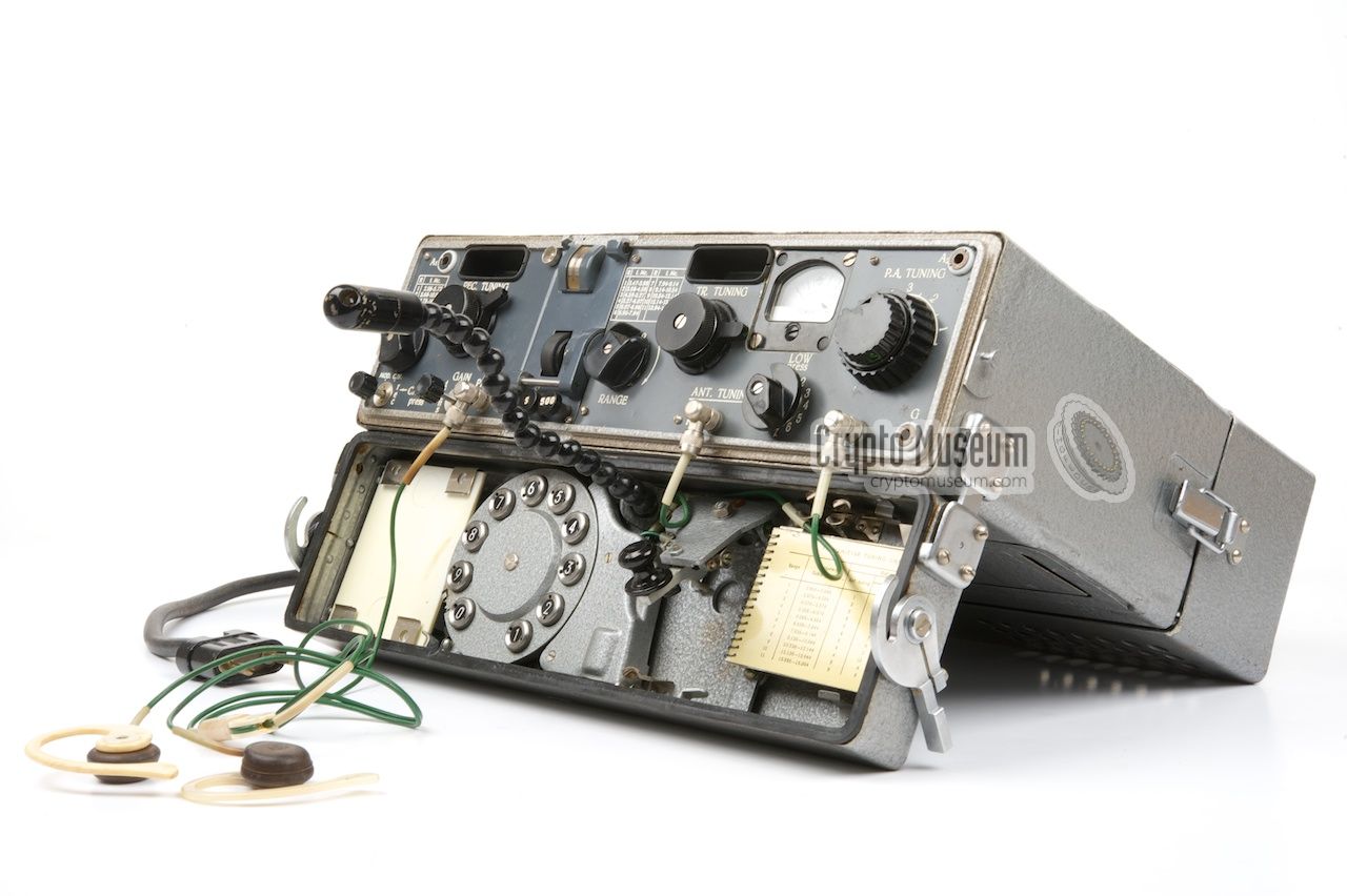
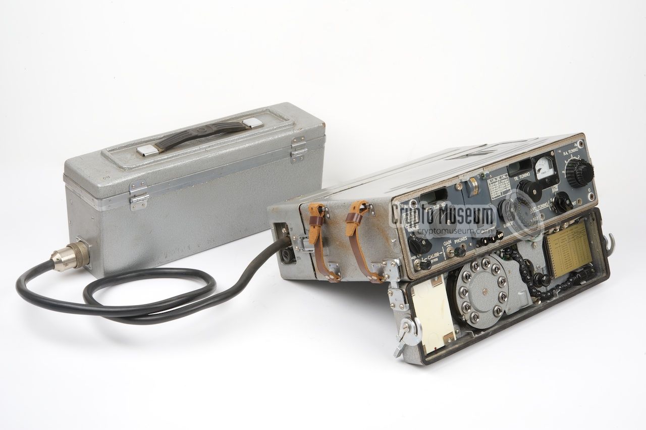
The image above shows the three main units. The PSU (Unit B or Unit C)
is fitted to the bottom of the transceiver by mating the three female
connectors with the male sockets of the transceiver, and is held in place
by two metal locks at the sides. Converting the transceiver from, say,
AC to DC involves just the removal of the AC PSU (Unit B)
and replacing it with the DC PSU (Unit C).
|
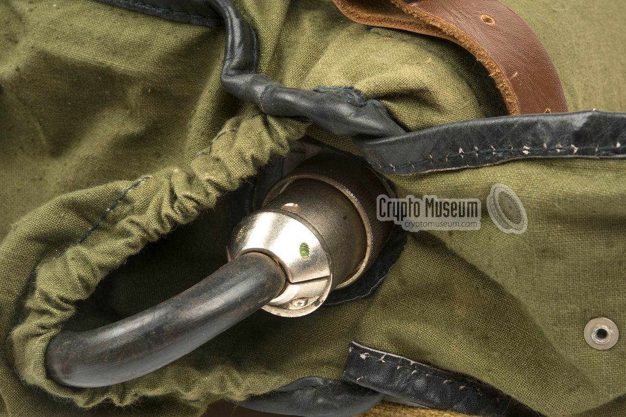
When using the R-353 in the field, it was powered by an external
12V DC power source, such as the battery of a vehicle, the (optional)
battery belt,
or the special external battery.
The AC PSU
was removed from the R-353 and the (optional) DC PSU was installed
in its place, as shown here:
The DC PSU has a fixed power cable with a large circular connector at
the end. This connection can be placed directly into the socket of the
external battery as shown above. It also fitted the battery belt
directly. The battery could be recharged from the AC mains by means
of a separate battery charger or manually by means of the
hand crank-operated power generator. It was alo possible to
connect the DC PSU directly to the battery of a car with the
cigarette lighter plug.
|
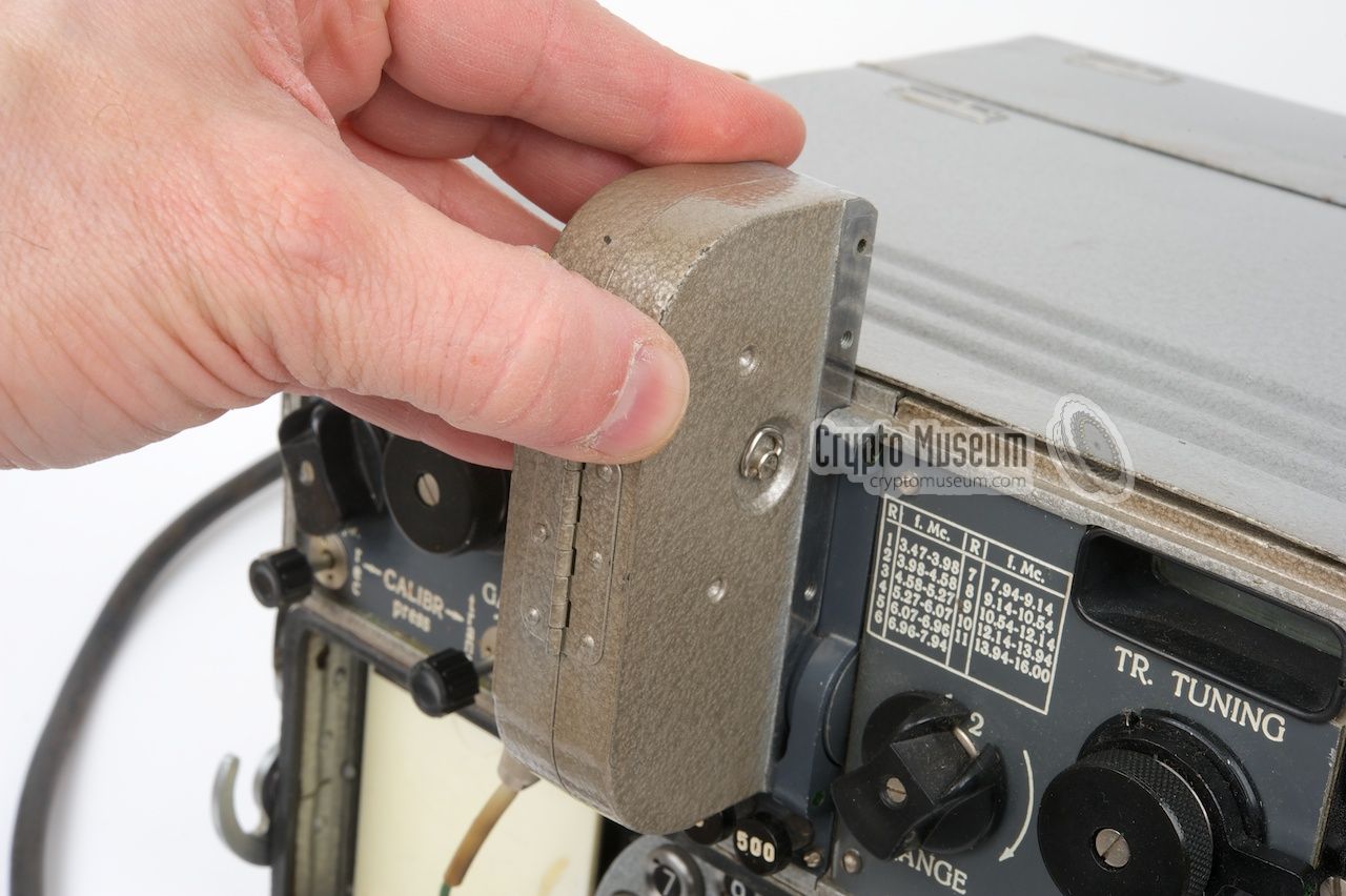
The full operating instructions of the R-353 are only available in the
original manual [A] in the Russian language.
Fortunately however, the Russians
were smart enough to include a quick guide in English
as part of the Tuning Chart,
a small aluminium booklet that is mounted
inside the top lid of the radio.
These instructions
can be used as a guide when operating the radio.
➤ Read the full instructions
|
|
|
Sending messages in morse code
|
|
|
|
The R-353 was able to send messages in
morse code (CW)
in the following manners:
|
|
In case of an emergency it was possible to use the R-353 for manual
transmission of messages in morse code,
by using the built-in morse key.
This allowed any kind of message to be sent, even plain text, but
required the operator to be very experienced in giving and taking morse code.
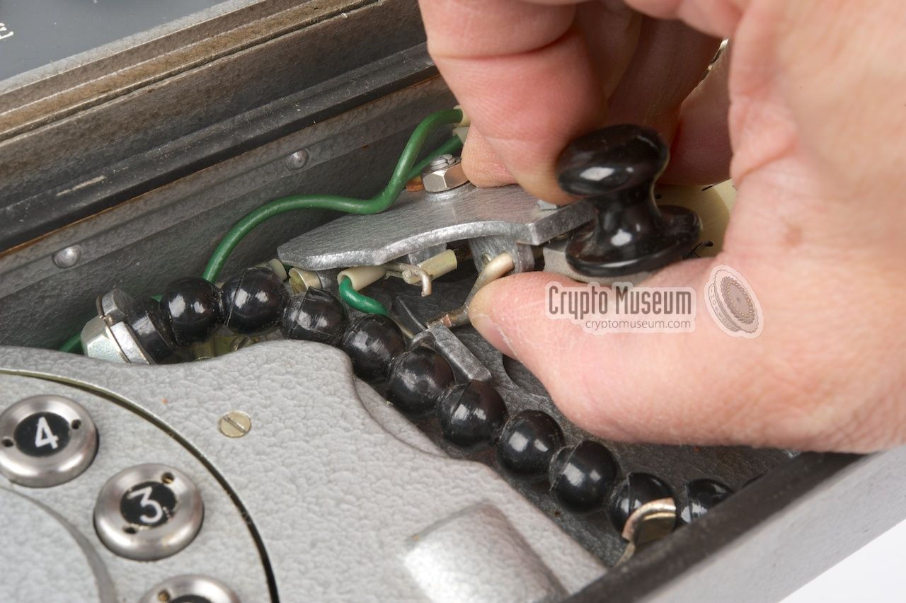
|
For this purpose, a small manual morse key is mounted inside the top lid
of the transceiver, to the right of the rotary dial. It is constructed in
such a way that it can be lifted somewhat to lock it into a more suitable
position. When the radio is placed horizontally on a table in the
assumed tilted position, the morse key should have the proper angle for
convenient manual operation.
Before the manual morse key can be used, it should be connected to the
socket marked KEY at the bottom edge of the transceiver. The plug is normally
stowed above the tuning chart.
|
|
|
After use, the morse key needs to be lowered again before the top lid can be
closed. This is done by pusing a spring-loaded lever
at the underside of
the key towards the rear and then pressing the key down. It is unlikely that
the manual morse key was used frequently as most spies and agents, especially
in the latter part of the Cold War, were not capable of giving morse code.
|
|
|
2. Semi-automatic transmission
|
|
|
|
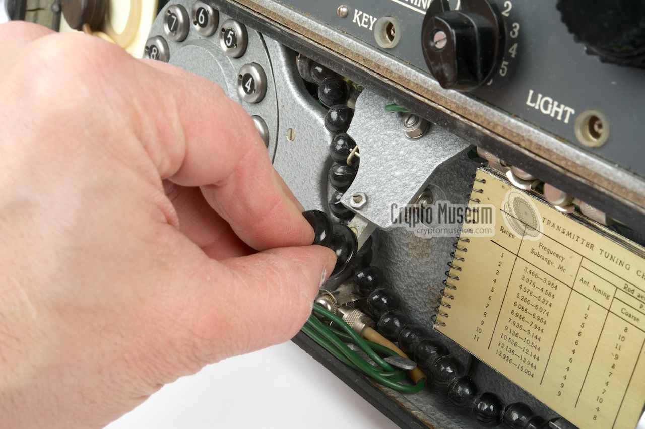
Another way of sending an emergency message is by using the semi-automatic
morse dial. This would be particularly useful if the operator was unable to
send messages in morse code manually at a reasonable speed. Unlike the
manual key, the dial is only suitable for numerical data (0-9).
|
The semi-automatic dial is located at the center of the interior of the top
lid and is connected in parallel with the manual morse key.
When the lid is open and the radio is in its tilted
position, the numbers of the dial are clearly visible.
Before it can be used however, the appropriate plug has to be connected
to the socket marked KEY at the bottom edge of the transceiver's font panel.
The radio is now ready for sending numercial messages in the usual manner.
This means that the message has to be
encoded manually first, e.g. by means of
a One-Time Pad (OTP) cipher.
|
|
|
Once the frequencies are set and a radio link with headquarters is
established, all the operator needs to do is dial the numbers in the
correct order, using the circular dial.
This involves pressing down the number and (whilst holding it down)
rotate the dial clockwise until it blocks,
and the releasing the number. The choosen number will now be sent in
morse code. Although this is a convenient way of sending messages without
any knowledge of morse code, it is still fairly slow compared to a
burst transmission
and therefore a potential candidate for
radio direction finding.
|
|
|
3. Automatic transmission
|
|
|
|
The best and certainly the safest way of sending messages is by using
the built-in keyer for a fully automatic transmission.
This requires the (pre-coded) numerical message to be recorded onto
a metal magnetic tape, which is then transmitted at very high speed
as a so-called burst.
|
The high-speed keyer is located at the front panel, mounted
between the receiver and the transmitter.
It is the smallest of the tree
units and consists of a reading head, a rubber driving wheel and three
control buttons (R, S and 250). 1
Before a burst transmission can take place, the plaintext message first
has to be coverted into a numerical message by means of a conversion table
or the unbreakable One-Time Pad (OTP) cipher.
The encoded message then has to be recorded
onto a small magnetic tape cassette by means of separate device:
the burst encoder.
|
|
|
The burst encoder is a small external device with a numerical dial
similar to the one that is used for semi-automatic morse transmission.
For recording, the tape cassette is attached to the rear of the burst
encoder, after which the numbers are dialled by means of a small pen.
This records the numbers onto the tape is a passive manner,
meaning that no external power is needed for this.
A full description of this process can be found in our
special section about burst encoders.
➤ Full description of the burst encoder
|
-
On some models, the high-speed keyer runs at double speed, and
the rightmost button has 500 on it.
|
|
Coding a message is a quite laborious task. First of all, a textual message
has to be converted to some kind of numbering scheme of which there were
many around. Next the numerical message had to be
encrypted with some cipher,
so that an eavesdropper
would not be able to read it.
|
Although various manual encryption methods
were used by Eastern Block spies and
agents, such as matrix transpositions and
codebooks,
the most common one (also the most feared one)
was the One-Time pad (OTP) cipher.
When used correctly, this cipher is unbreakable.
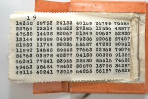
The OTP was a small booklet with very thin pages, each of which contained
a sequence of random numbers. Only two copies of the OTP existed:
one in the hands of the agent and one at the receiving end. Each page was used only once and was destroyed immediately after use.
|
|
|
The message is encrypted by adding each of the digits on the OTP
to one character of the plaintext. If the OTP consists of truely random
numbers, the result bears no relationship to human-produced text and will
defeat any frequency analysis.
At the receiving end, all that has to be done is subtract the numbers
again to reveal the original message.
One of the disadvantages of the OTP is the
problem of key-distribution: both parties need to have sufficient supply
of OTP sheets.
➤ More information about the OTP
|
The R-353 has been used by many East-European and Soviet agents
in various West-European countries from the
late 1960s, well into the 1980s and was captured by western agencies
on a number of occasions. One documented event was the capture of
a Dutch man, acting as an
East-German agent in The Netherlands, in 1969.
When he was exposed, the Dutch intelligence agency
BVD
(now: AIVD)
found a fully operational R-353 in his home, along with a number of
cassettes
and a One-Time Pad cipher booklet
of which a number of pages had already been used [1].
|
The R-353 was supplied with a wide range of accessories and add-ons.
Depending on the actual application, some of these accessories were optional.
In situations where the R-353 was hidden inside a home, for example,
the canvas transport bags were not supplied. The same is true for the
battery and the belt.
Below we have tried to compile a complete list of possible accessories.
Click any of the thumbnails below to jump straight to the relevant description.
|
The R-353 was supplied with one of the most advanced
burst encoders of its time.
It consists of a small unit with a telephone-style
circular dial and one or more small metal tape cassettes.
The dial is used to record numerical messages onto magnetic
tape, much like the American
AN/GRA71 burst encoder does.
Once recorded, the tape cassette is removed and fitted onto
the keyer at the front panel of the R-353.
➤ More information
|
|
|
One or more tape cassettes were supplied with each R-353.
Pre-coded numerical messages
are recorded onto such a tape cassette,
using the supplied burst encoder. During a transmission it is played
back at high speed (burst) by the keyer.
In espionage, multiple cassettes were used, so that one person could encode
the message and deliver it at a predetermined spot (dead drop) where
he would pick up a new blank cassette.
➤ More information
|
|
|
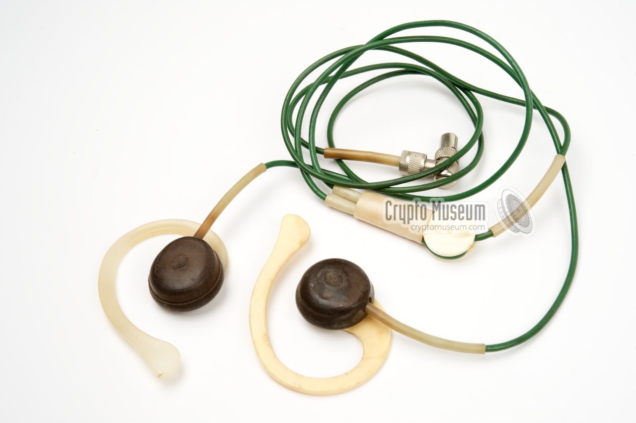
The audio output power of the receiver is just enough to drive a pair of
earphones. A suitable set is supplied with the radio and is normally stored
inside the top lid at the left hand side, with its cable cleverly wound around
two metal stubs and its plug seated in a special holder.
The original earphones are often missing from the surviving R-353 sets
and finding a suitable one is nearly impossible due to the rareness of the plug.
The same plug is used for the morse key and for the work light.
|
|
|
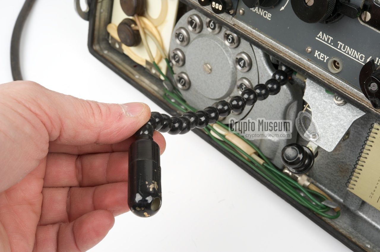
A typically Russian innovative bendable work light is mounted inside the
top lid of the R-353. The base of the light is mounted to the upper edge
of the top lid, to the right of the semi-automatic morse dial. The head
of the lamp is seated in a metal clamp at the bottom right.
The lamp can be erected by taking the head from the clamp and adjusting
it to the desired position. The lamp is powered by placing the rightmost
connector of the top lid into the socket marked 'LIGHT' on the front panel.
|
|
|
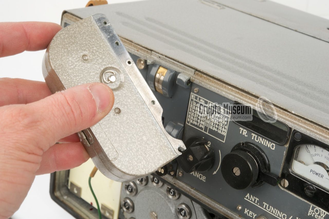
Inside the top lid, at the right hand side, is a small spiral-bound
booklet with 7 aluminium pages of about 8 x 5 cm.
The booklet contains the optimum tuning settings for each of the 11
transmitter frequency ranges (3 pages) plus 4 pages of operating instructions.
The booklet cannot be removed and is held in place by two bolts (at the rear)
and a retaining clip at the top right.
|
|
|
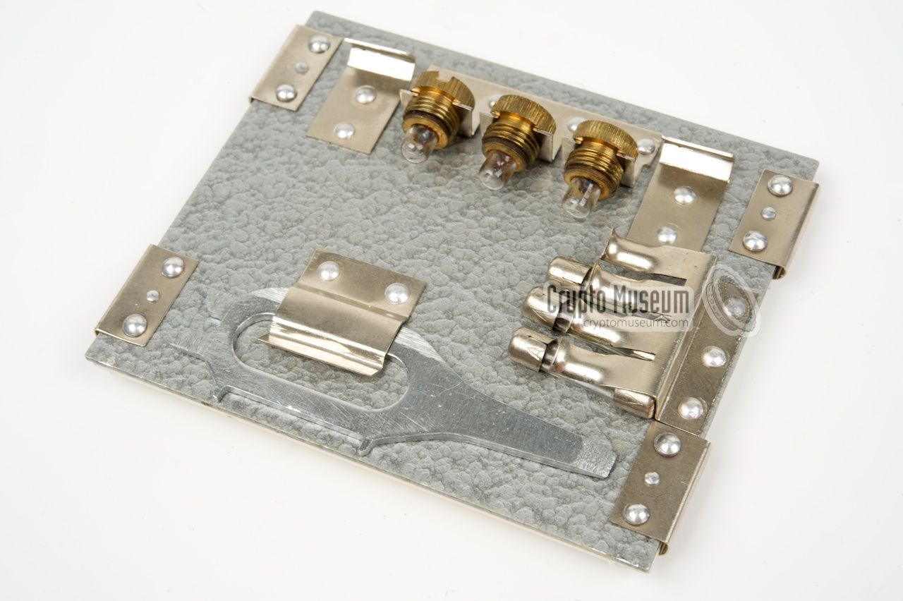
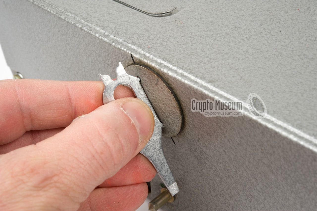
A small set of spare fuses and lamps is stowed under the white plastic
panel at the left hand side of the top lid. This panel normally holds
the earphones, but can be pulled away to reveal the spare parts.
This panel also holds a special screwdriver
that is needed when replacing the light bulbs of the
projection scales.
When placing back this panel, ensure that the red dot (if present)
is at the bottom. This ensures that the lamps and fuses are kept in place
by the polystyrene foam.
→ Warning
|
|
|
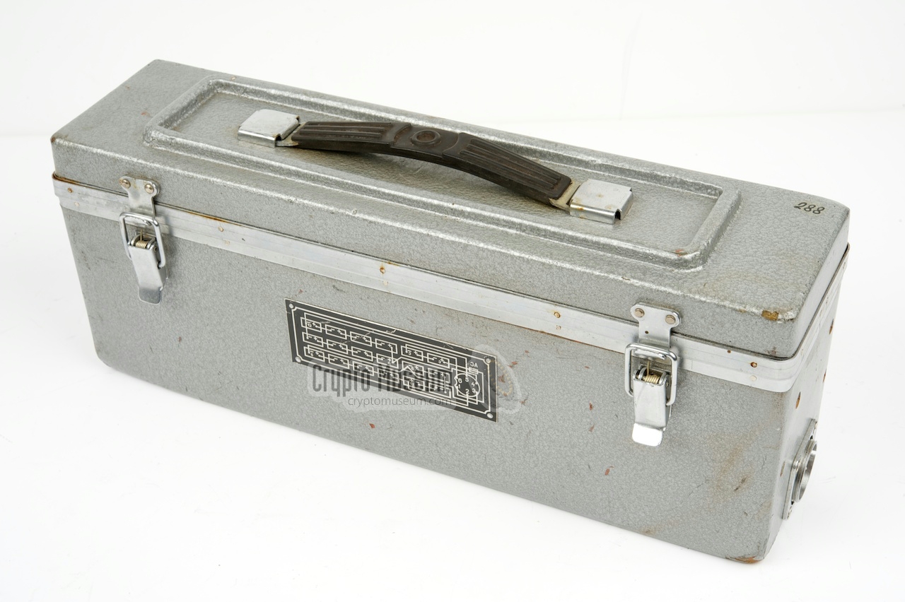
The R-353 was supplied with a so-called ZIP box, a metal storage box
with tools, spare parts and maintenance materials, that allowed a technician
to repair a faulty unit in the field.
The ZIP box contains spare valves, a toolkit, a soldering iron,
spare light bulbs, fuses, spare magnetic tape and other maintenance materials.
➤ More information
|
|
|
|
|
AC mains power supply unit
|
|
|
By default, the R-353 is supplied with a mains AC power supply unit (Unit B)
that allows the transceiver to be powered from virtually any wall socket
in the world. A voltage selector at the rear of the unit allows the
appropriate mains voltage to be selected between 90 and 240V.
The AC PSU is mounted to the bottom of the transceiver and supplied all the
necessary internal voltages directly to the receiver and the transmitter
via the three 12-pin connectors.
|
|
|
When using the R-353 in the field, it might be necessary to power it
from an external 12V source, such as a portable battery or a battery belt.
If this is the case, the standard AC power supply unit or PSU (Unit B)
should be replaced by the DC power supply unit (Unit C) shown here.
It is mounted to the bottom of the transceiver and converts 12V DC into
all internal (high) voltages needed by the receiver
and the transmitter, via the three 12-pin connectors.
|
|
|
When powering the R-353 directly from a 12V battery of a vehicle,
this purpose-made adapter could be used to connect the DC PSU
(Unit C) of the R-353 to the cigarette lighter socket.
Appropriate sockets for this plug are present in nearly any civil
car, van or truck.
|
|
|
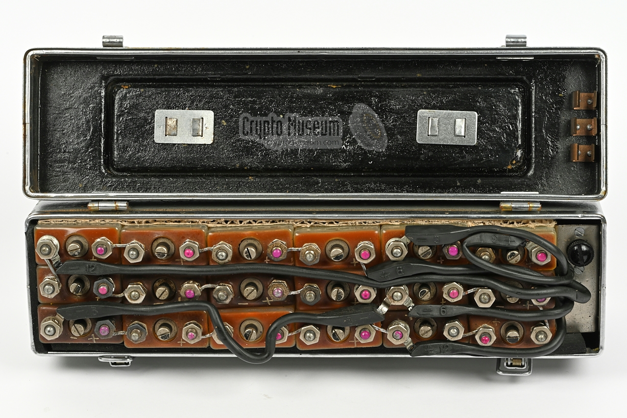
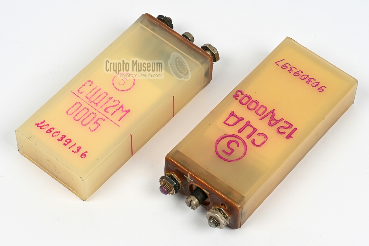
By default, the R-353 was mains powered, using the standard PSU attached
to the bottom of the unit. The standard PSU could also be replaced by a
power inverter (DC PSU),
so that it could be powered from an external battery source.
The standard battery unit is shown in the image on the right.
It contains 18 silver-zink batteries,
filled with potassium hydroxide. The unit is wired according to
the wiring diagram at the front.
The voltages are available on a connector at the right side.
|
|
|
When using the R-353 in the field, an alternative to the external battery
is the (optional) battery belt that can be worn around the waist.
It holds 11 silver-zink batteries, filled with
potassium hydroxide, fitted inside individual pockets.
The flying lead of the DC PSU (Unit C) can be connected straight to the
battery belt. A small switchbox on the belt allows the 12V power supply to be
turned on or off.
|
|
|
|
When the external battery or the battery belt was used (see above) this
separate power supply unit was used to charge the batteries.
It has two fixed wires: one that
connects to the battery case (left) and one for connection to the mains
wall socket (right).
|
|
|
If no mains power is available, the battery can also be
charged with the small hand-operated power generator.
Charging the batteries this way is not an easy task and takes
several hours, for just a few minutes of operation.
The power generator can be carried on the body by using the
canvas straps, but it can also be stored in the canvas
accessory bag. A special power cable
is needed to connect the battery.
|
|
|
As the battery for the R-353 has a non-standard connection, the
normal charging cable supplied with the hand-crank-operated power
generator can't be used. Instead, a suitable one was supplied with the
R-353.
It has a military 4-pin female connector that mates with the generator
at one end, and a large 7-pin female connector that mates with the
R-353 battery at the other end.
|
|
|
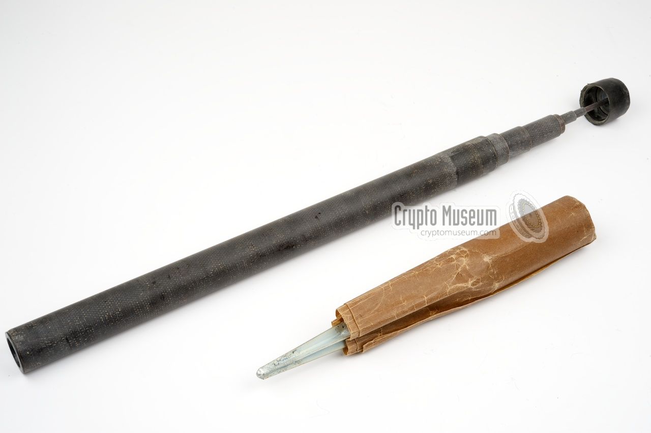
There are several ways of connecting an antenna to the R-353,
but in most situations a (long) wire is used for this.
When operating in the field, an (optional) telescopic fibre
mast was supplied, so that the wire was kept free from the
ground.
In addition, a ground pin was supplied for connecting the counterpoise
socket (G) at the front panel to mother earth.
|
|
|
The R-353 was supplied with two wire antennas: a short one of about 4 metres
for the receiver,
and a long one of approx. 12 metres for the transmitter.
There was also a 4 metre wire for connecting the counterpoise.
The image on the right shows the metal spool with throwing weight on which
the wires were supplied.
|
|
|
|
When operating the R-353 from within a vehicle, a special
(optional) car window mount was supplied. It was clamped
in between the window and the pane, and kept the fibre mast
in the upright position.
According to the manual, two such clamps were needed.
|
|
|
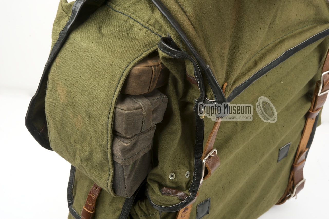
For field use, on optional canvas transport bag was supplied.
It allows the R-353 to be operated from within the bag and has
pockets for burst encoder, battery, antenna and cables.
In order to allow the radio's projection scales to be read
in broad daylight, the front flap of the canvas bag can be used
as a hood, as shown in the image on the right.
|
|
|
|
An additional canvas bag was supplied to carry the other accessories
when the R-353 was used in the field. It has space for the hand-operated
power generator, the spares kit, tools, further antennas and additional
cables.
|
|
|
|
The actual R-353 transceiver itself (i.e. without any of the power supply units)
consists of only three major building blocks: the receiver, the transmitter
and the keyer. These builing blocks are mounted inside the enclosure as two
sub-assemblies: the receiver
and the transmitter/keyer.
|
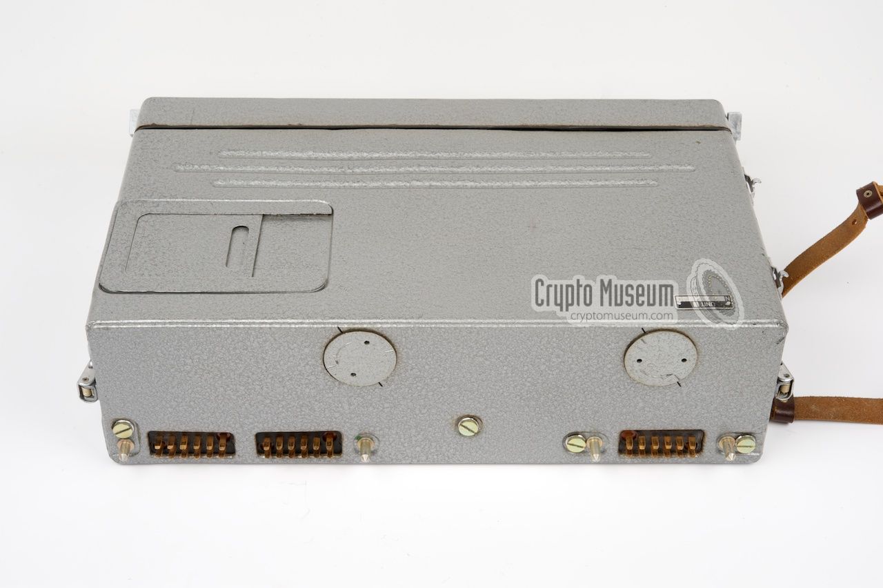
The sub-assemblies can easily be replaced in the field in case of a malfunction
or defect, by removing the 4 large bolts at the
rear of the unit.
The assemblies can then be pulled-out from the front. The keyer is bolted onto
the left side of the transmitter,
but can easily be separated by loosening just
two bolts. The image above shows the three building blocks outside the
case.
|
|
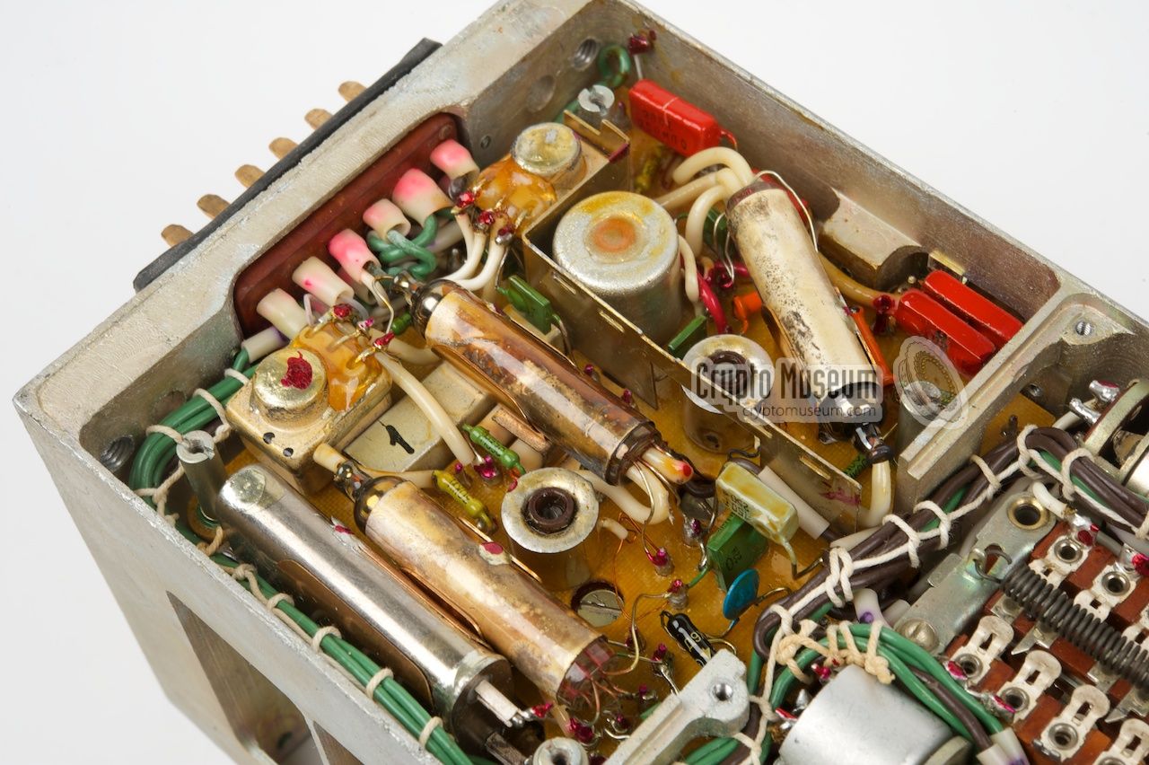
The receiver is built on a die-cast chassis with circuits, coils and other
parts at all sides. The HF parts are shielded by removable metal panels
and consist of 11 sub-minature valves (tubes) divided over several small
PCBs. It is fully stand alone and is not connected to the transmitter.
|
The receiver module is powered directly by the separate Power Supply Unit
(PSU) via the large 12-pin socket at the rear. All controls and connections
are at the front panel. The receiver covers all frequencies between 3 and
16 MHz, divided over three ranges, and is suitable for the reception of
phone (AM) as well as morse signals (CW), selectable
with the 2-position modulation-switch at the bottom left of the
front panel.
Frequency readout is via a projection scale
at the upper side. It consists
of a transparent disc, a light bulb, a lens and a matte screen.
→ More
|
|
|
The receiver is a superheterodyne with IF stages at 2600 kHz and 465 kHz
and a selectable Burst Frequency Oscillator (BFO) for the reception of
CW signals (morse). The detected LF signal is amplified to earphones level
and is also used for driving the Automatic Gain Control (AGC).
|
|
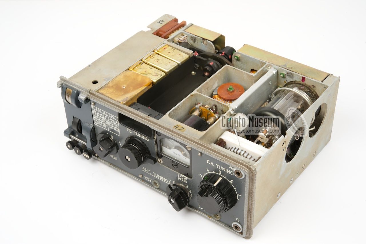
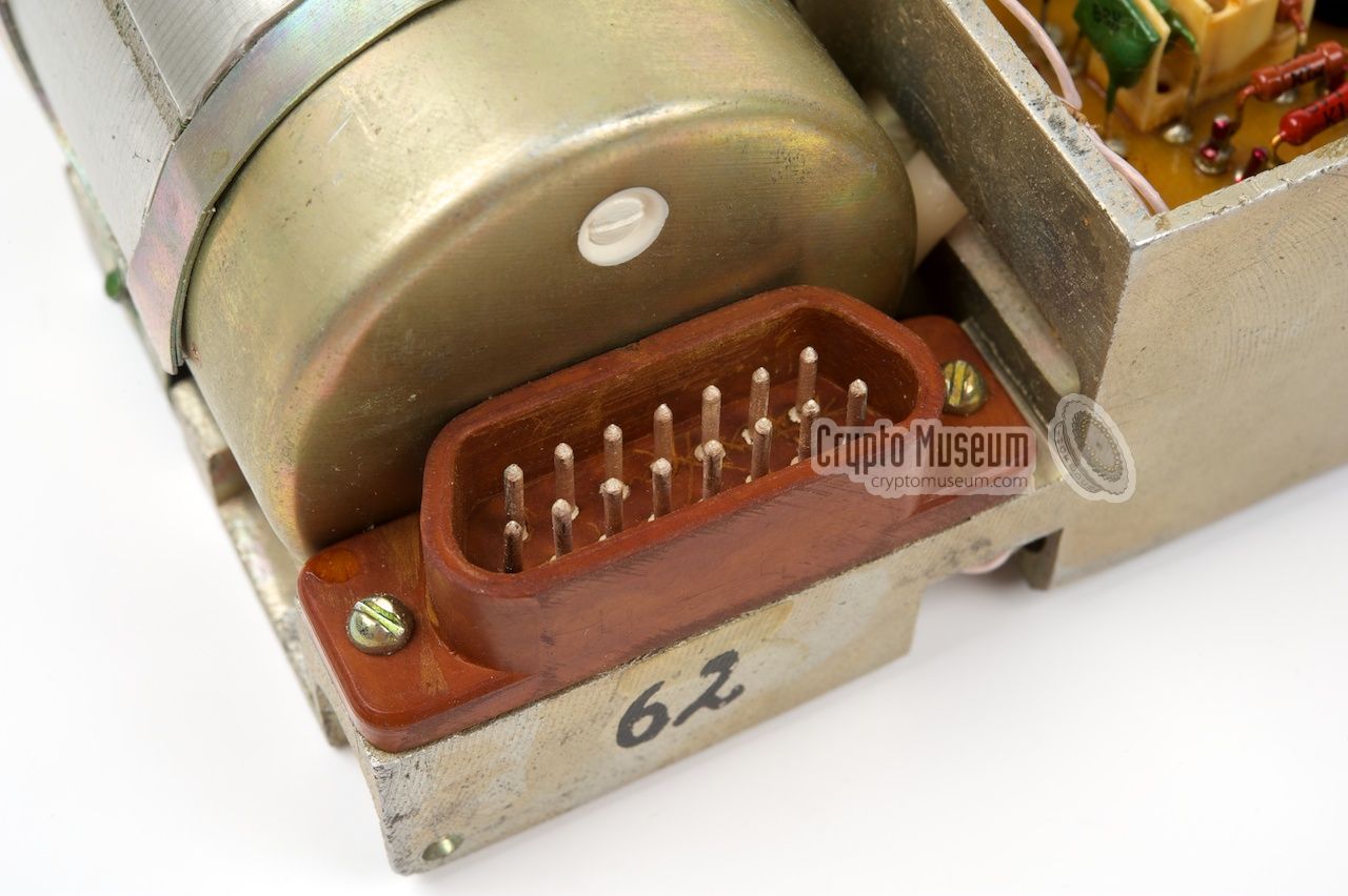
The transmitter is the largest of the three modules and has the keyer
bolted-on at the left hand side. The keyer connects to the transmitter
via a 15-pin bakelite connector,
and can easily be removed by releasing
two recessed bolts. The image below shows the transmitter/keyer combo.
|
The transmitter itself is built onto a heavily compartimented die-cast chassis,
similar to German military radios from the WWII era. The circuits consist
of 4 sub-miniature valves, plus a fairly large one for the HF Power Amplifier
(PA).
The transmitter is powered directly by the PSU
via two 12-pin sockets at the rear. All further connections and the controls
are at the front panel.
The transmitter is shown in the image on the right, with the keyer in place
at the left hand side.
The PA valve,
which needs cooling during transmission,
is clearly visible at the right.
|
|
|
The transmitter is free-running, which means that it can be adjusted to any
frequency in the 3 - 16 MHz range, independently from the receiver.
For this
reason the transmitter has its own projection scale.
Like with the receiver, the full frequency span is divided over 11 ranges.
As the transceiver is only suitable for CW (morse) it is driven directly
by the keyer, as shown here:
The exiter generates the basic adjustable frequency and is enabled by the
manual key,
the semi-automatic morse keyer,
or by the high-speed keyer.
This base frequency is then doubled twice before it is amplified to approx.
50W by the Power Amplifier (PA). An adjustable antenna tuner is used to
match the antenna to the output stage of the transmitter. An analogue meter
is present to allow the PA and the antenna tuner to be adjusted
for maximum antenna current (gain).
|
|
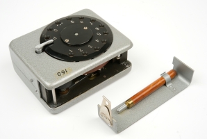
The keyer, or burst transmitter, is the smallest of the three modules.
It is mounted to the left side of the transmitter and connects to it by
means of a 15-pin bakelite connector.
After releasing two recessed bolts,
the keyer can be separated from the transmitter by disconnecting
the connector.
|
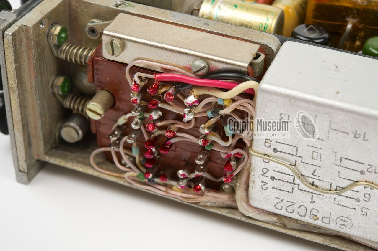
The keyer consists of a die-cast chassis with two printed circuit boards,
(one at either side of the chassis), some passive components
(bottom) and an electro-motor that drives the tape.
It is the
only module of the R-353 that is fully solid-state, meaning that
only transistors are used.
The image on the right shows the right side of the keyer seen from
the top. The motor is visible at the top left, just behind the
bakelite plug.
At the front panel is a rubber wheel that drives the tape in the cassette,
and a 2-track magnetic head that reads the data stored on the tape.
|
|
|
The data is stored on the tape as a series of short pulses on two different
tracks. The pulses on track 1 cause the keyer signal to go high (tone on),
whilst the pulses on track 2 cause the keyer to go low again (tone off).
The block diagram below shows how this works. The tape is at the left.
The signals from the two channels
are first amplified and then limited before they drive an RS flip/flop.
The resulting signal is fed to the keyer and eventually to the transmitter (TX).
The output from the flip/flop is also used to control the speed of the motor,
which in turn drives a gear box and eventually, via a rubber belt, the tape
cassette. There are 2 versions of the high-speed keyer: one that sends at
250 words-per-minute (WPM) and one that does 500 WPM.
➤ More about reading data from the tape
|
|
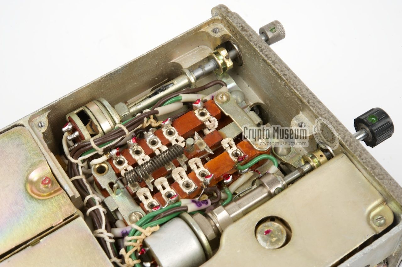
RX and TX frequency are fully adjustable over the entire 3-16 MHz frequency range,
and rely on projection scales, a method that is commonly used in Russian equipment of
the era. A circular transparent disc with very small numbers and
lines printed on its surface,
is lit from the rear by a small light bulb. Via a small lens, the image
is then projected onto a matte screen at the front panel.
The transparent disc contains multiple concentric scales, one for each frequency
range. Selecting another range, by rotating the RANGE selector,
moves the transparent disc up or down.
|
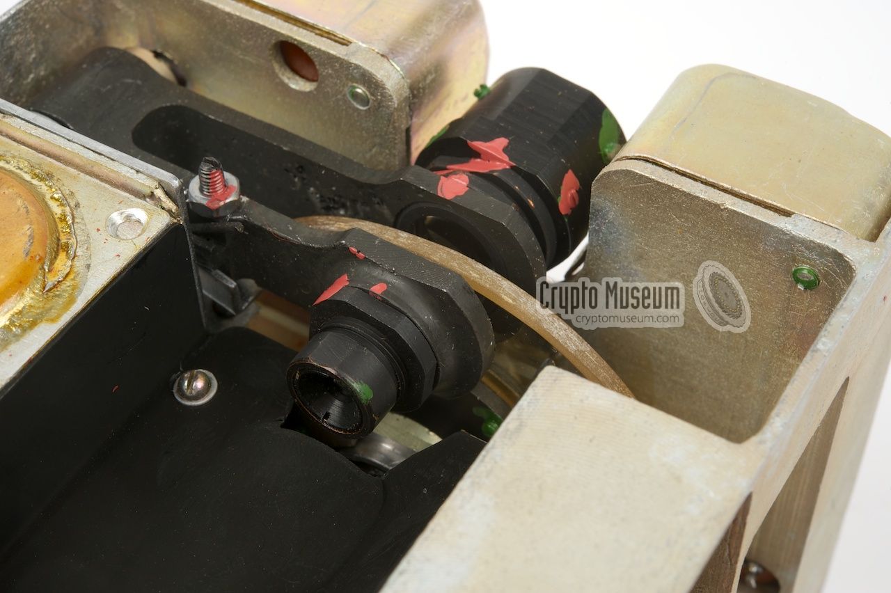
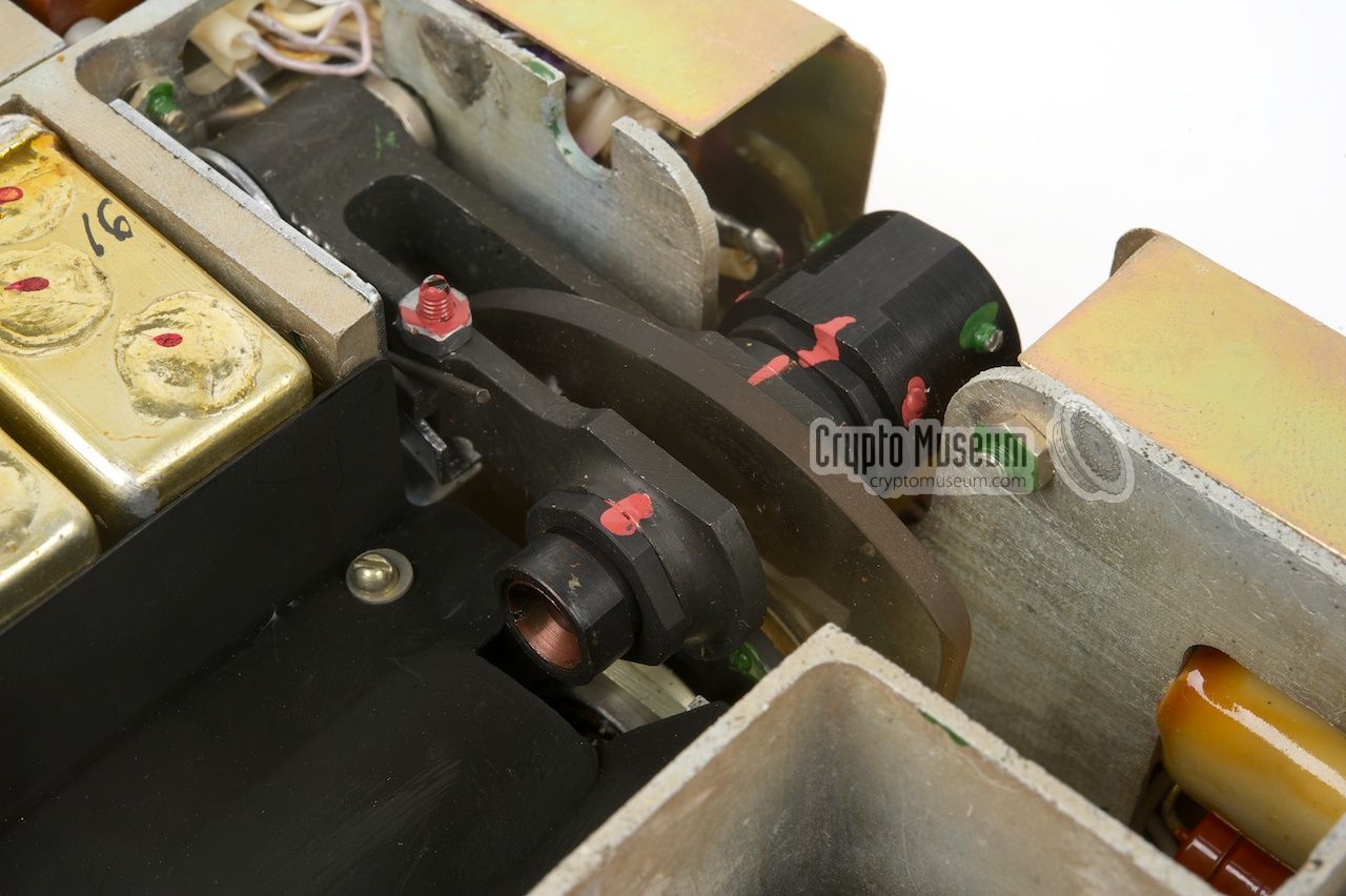
The image on the right shows a close-up of the scale projection system inside
the receiver. The projector inside the transmitter is identical. The black unit at the top right holds the light bulb.
Reading the scales in bright daylight may be difficult,
but if the lamp is broken,
the frequency can no longer be checked.
For this reason, a few spare light bulbs are
present in the small spares compartment
in the top lid, as well as in the
separate spares kit.
Replacing the light bulbs is pretty straightforward.
Remove the PSU in order to get access to the
rear of the transceiver.
|
|
|
|
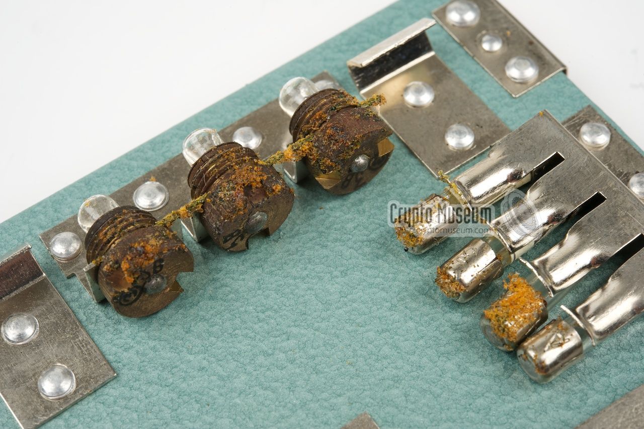
Please note that some of the materials used on the R-353, such as the rubber
gaskets, the plastic ear clips and some types of polystyrene foam,
have the tendency to release toxic fumes over time,
even after all these years. These fumes may
potentially leave permanent marks on plastics and painted surfaces, and
may also cause oxidation of some vital parts or the radio's case.
|
One example is the plasticizer that is used for the wires of the
earphones and the ear-clips.
Over time, the plasticizer will be released from the cable
and may cause damage to other plastic parts or even to the hamerite paint
of the case.
When storing the R-353 for longer periods of time, it is advised to
leave the top lid open. It allows the potentially harmful fumes to escape.
If this is not possible, it is advised to remove the earphones from the
top lid, pack them in an airtight plastic bag and store them elsewhere.
|
|
|
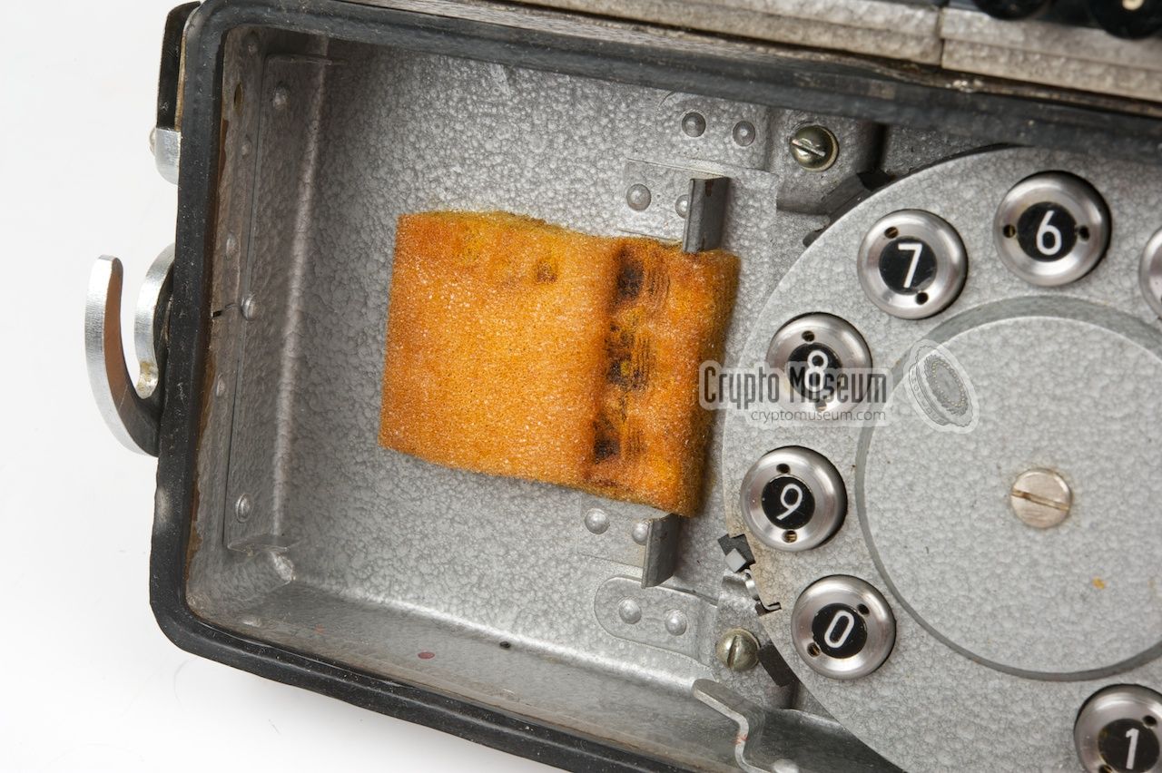
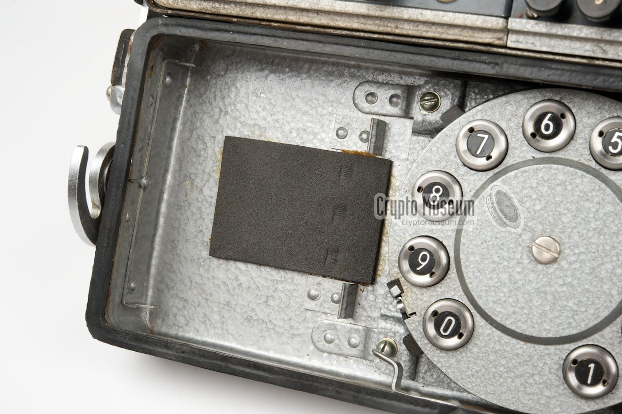
Furthermore, the polystyrene foam
that is located under the spares panel
inside the top lid, as shown above, should be removed.
The foam is used to keep the
fuses and lamps
in place during transport, but over time the fumes released
by the polystyrene will cause corrosion (even today).
Replace the foam by a thin piece of self-adhesive synthetic rubber
of the same size, like this.
|
Device Short Wave (SW) transceiver Purpose Agent-to-Base burst transmissions Model R-353 Manufacturer Proton (Charkiv, Ukraine) Country USSR (Ukraine) Year 1969 Predecessor R-354 Successor R-394K Frequency 3 - 16 MHz (3 ranges) Transmitter 5 valves (4 miniature valves plus 1 PA valve) Output 50W (with AC PSU) or 40W (with DC PSU) Receiver 11 miniature valves Sensitivity 5µV (CW) or 15µV (AM) IF 1 2600 kHz IF 2 465 kHz Keyer 250 or 500 WPM (depending on model) Front panel Grey with English labels Scale Projection scale frequency readout for TX and RX Mains AC PSU: 90 - 240 V (switch-selectable) Battery DC PSU: 12 V Dimensions ? Weight ?
|
- AIVD, Short description and image of a captured R-353
Website. Retrieved November 2009.
- Chris Vos, et al. De geheime dienst: verhalen over de BVD
ISBN: 90-8506-181-4 (Book with DVD, Dutch).
- Karsten Hansky, Sound samples of R-353 transmitted signals
Germany, July 2017.
|
|
|
|
Any links shown in red are currently unavailable.
If you like the information on this website, why not make a donation?
© Crypto Museum. Created: Saturday 07 November 2009. Last changed: Saturday, 27 September 2025 - 13:36 CET.
|
 |

|
|
|


