|
Cold War USSR KGB GRU ← R-394KM
Digital shortwave agent radio set with burst encoder · USSR
R-394T, codenamed Strizh-T (Russian: Стриж), 1 is a digital short wave
(SW) agent radio set with built-in
burst encoder,
also known as a spy radio set,
developed in the early 1980s in the former Soviet Union (USSR).
The device is electrically identical to the military R-394KM,
but has English lettering, provisions for western accessories and supplies,
and comes without a storage case.
It was typically used in clandestine operations by
intelligence services
like the KGB and the GRU.
|
Agent radio sets generally do not have a model/serial number tag,
but from various sources it has been confirmed that the radio set shown
here was designated R-394T (Strizh-T) [6]. At least three variants existed
(T, TS and TSK), two of which have meanwhile been found [5].
The devices were typically
used by Soviet intelligence services
like the KGB and GRU, but also by the services of other
Warsaw Pact countries, such as the
East-German Stasi.
The military version of the set – the R-394KM – was intended for
use by Special Forces (SF) and behind-enemy-lines operations.
Both versions of the radio set were developed in the early 1980s
and remained in production until at least 1989.
The radio shown here was probably manufactured in 1986 and was discovered in
an underground cache in (West) Germany in 2004, complete with fully
operational batteries [4]. In a similar event, a fully intact R-394KM
was found in a cache in (West) Germany in 2020 [7].
|
 |
-
Стриж (Strizh) is the Russian word for swift (bird).
|
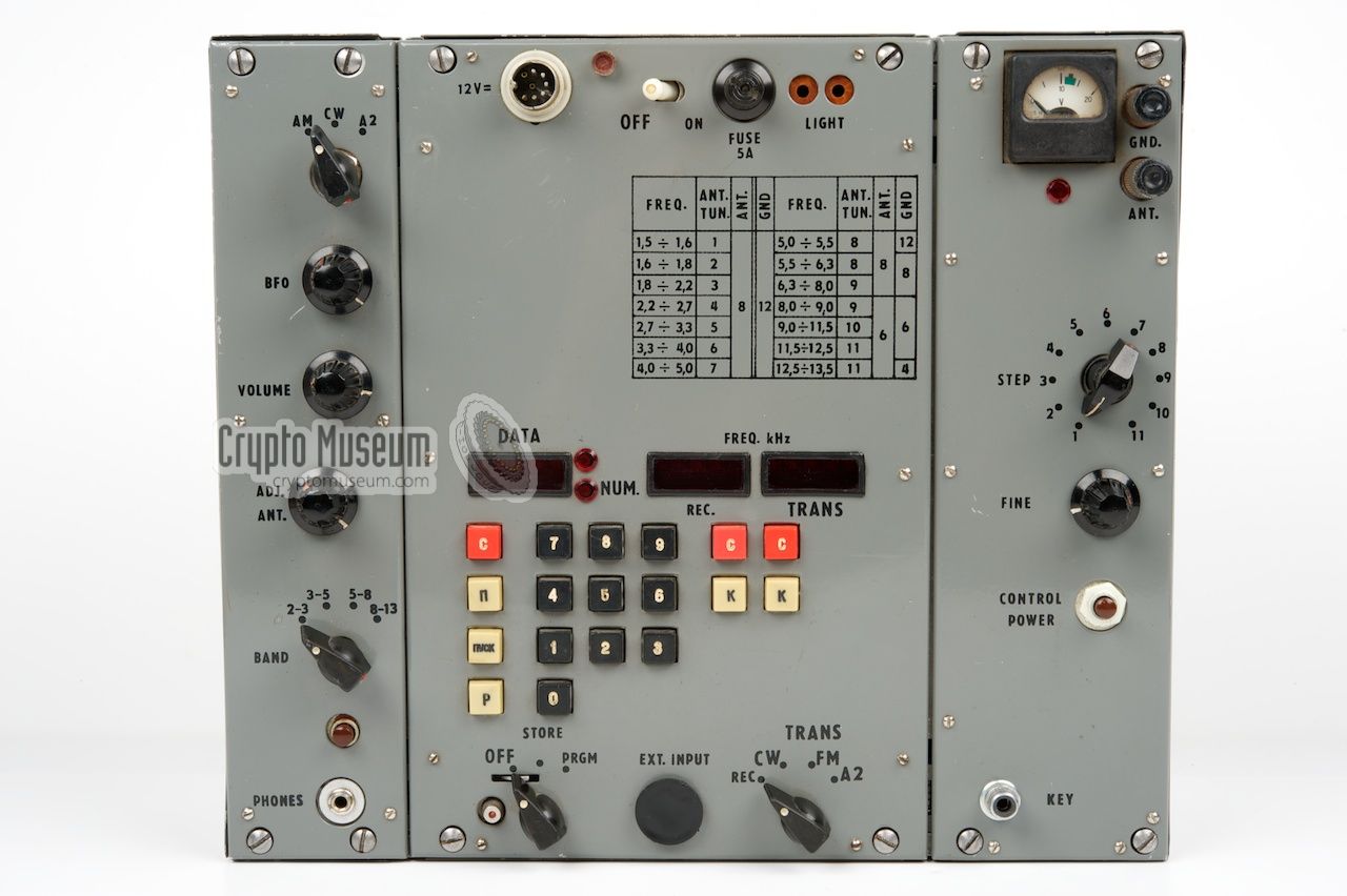
The controls of the R-394T (Strizh-T) are nearly identical to those of
the R-394KM with some small differences.
The set can only be used if all three units
are mounted together and a 12V DC source is connected to the
power socket at the upper edge of the DSU. Turn the unit on with the white
switch to its right and set the TX MODE selector at the bottom
right to REC (Receive).
Operation of the set is identical to the R-394KM, but the
connections are somewhat different. Rather than the typical Russian
military connectors, this version has commercial sockets, similar to the
ones found on western domestic equipment. Furthermore the set has English
text on the front panel, whereas the military version was in Russian.
All other differences are discussed below.
For a description of the operation, please refer to the
original operating instructions.
|
|
At least two variants of the R-394T have existed (probably three),
which we will refer to as Mark 1 and Mark 2 until the original designators
have been determined.
|
- Strizh-T/I
This is believed to be the oldest variant of the device.
The transmitter has a small meter (similar to the one on the R-394K),
and a fitting for a western 9V backup battery is present on top of the DSU.
Note that the power check button is at a different position.
This variant was rediscovered in 2022 by Jozef Burda in Slovakia [5].
- Strizh-T/II
This version has a large meter on the transmitter
(same as on the R-394KM), and has a
bay for a western 9V battery at the front
of the DSU.
Furthermore, the built-in morse key has been replaced by an RCA socket.
The device described here, is of this type.
|
|
The R-394T is based on the design of the (military) R-394KM.
It was designed in such a way that it could adapted for a variety of purposes,
including Special Forces, reconnaissance,
Stay-Behind, underground caches
and clandestine activities (espionage).
For use by intelligence agents, the set was not housed in the
typical military case of the R-394KM,
but came as three separate units that could be adapted for any type of
concealment (e.g. inside a common briefcase).
Furthermore, the units had english lettering on their
control panels. This was done for two reasons: (1) it would not immediately
expose the set as being Russian when it was accidently discovered by the
police, and (2) it was more appropriate for recruted agents that did not
necessarily speak (and read) Russian.
|
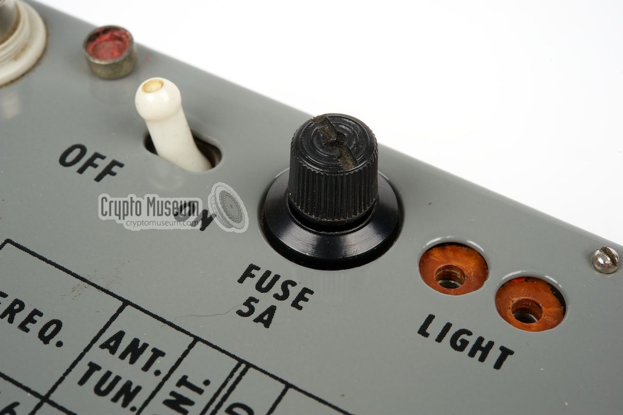
Depending on the area in which the radio would be used (target
country), the radio was adapted to locally availability
accessories and spare parts.
On this example, the typical Russian fuse holder has been replaced by
a western alternative. In case the fuse was blown, the agent could obtain
a new commonly available fuse from any local store, rather than ask for an
original (smaller) Russian one, which was not available in the west and
would certainly have raised eyebrows.
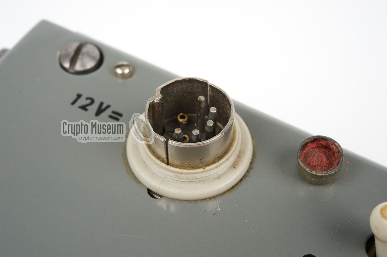
In the same vein, the military 4-pin power socket
was replaced by a more common 8-pin DIN socket. 1
|
|
|
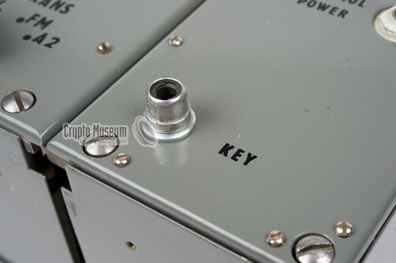
On a standard R-394KM,
a built-in morse key is present towards the front
of the transmitter. It allows messages to be sent directly in morse code
in case of an emergency.
As this was not very convenient - most operators were not capable
of giving morse code and if they were, they would have liked to use an external
key - the internal key was replaced by an RCA
CINCH socket.
|
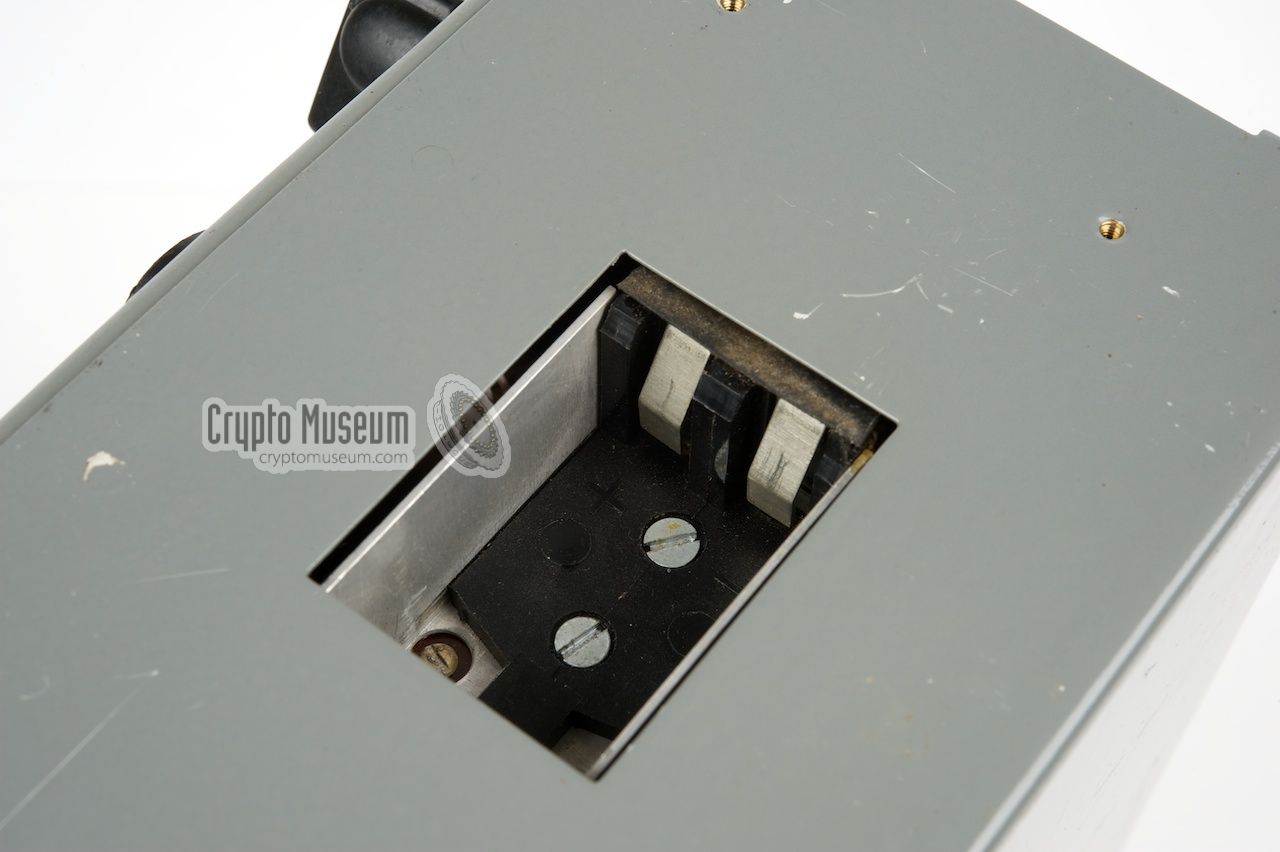
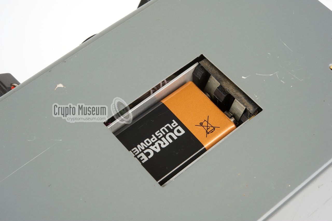
The position of the 9V backup battery needs some clarification.
On the military version of the R-394KM, the backup battery is located
under a removable oval lid on the control panel of the transmitter.
Below this panel is space for a cylindrical Acacia battery
(Russian: Акация), which is actually a stack of 6 circular 1.5V cells.
Although the holder for the Acacia battery is still present inside
the transmitter, there is no lid in the control panel.
As this type of battery was not available in the west,
a western-style 9V battery holder was added to the front or top of the DSU.
|
|
|
This allowed the agent to obtain a replacement battery from a local store
and install it through a rectanglular hole in the front of the DSU. Another
modification was the replacement of the 2-pin Russian headpones
socket by a standard western 3 mm jack socket, allowing any
ordinary earphone
to be used, such as the ones that were commonly supplied with portable radios.
The following differences with the R-394KM have been found:
|
-
This type of DIN connector
is actually not very common in Europe as it is
an 8-pin 262° version which is rather rare. This is probably why three of
the pins in the connector on our R-394T have been removed.
|
|
The speed at which a message is sent, depends on the selected transmission
mode:
|
- CW - 10 GPM
This is the so-called morse mode (CW). It is used for normal speed
automatic and manual morse code and allows 10 groups (of 5 numbers each)
to be transmitted per minute.
- A2 - 167 GPM
This is the so-called tone telegraphy mode (TT)
which allows 167 groups per minute to be sent.
This means that the longest possible message of 203
groups is sent in approx. 1.2 min.
- FM - 415 GPM
This is so-called phase telegraphy mode (FT) which offers the highest
security by sending the data at a speed of 415 groups per minute.
In this mode, the longest possible message of 203 groups
is sent in less than 0.5 min.
|
 |
|
Preparing a burst transmission
|
|
|
|
The leftmost display (DATA) on the DSU is used for the burst encoder,
together with the leftmost column of keys (С, П, ПУСК, Р)
and the black numerical key pad. After switching on the radio station,
check the battery voltage (CONTROL POWER)
and set the MODE selector to Receive (REC).
A message consists of a 5-digit header followed by a series of 5-digit
groups (datagrams) that are each separated by pressing ENTER (Р).
The DSU can hold 203 of such 5-digit datagrams.
|
Next, set the Memory Control selector, at the bottom left of the DSU,
to Program (PRGM) and enter the 5-digit header of the message using the
numerical keys. The numbers should be visible in the display immediately.
Terminate the header by pressing the ENTER-button (Р).
Now enter the message as a series of 5-digit groups and terminate
each group by pressing the Р-button. If you made a mistake, the
current group can be cleared by pressing the С-button. Multiple
messages can be entered by pressing the Р-key twice at the end of
a message.
|
|
|
When finished, set Memory Control to STORE. A message can be checked
by setting the Memory selector to PRGM again,
after which the first radiogram (i.e. the header) should be visible.
Now use the Р-button to step through the groups. Errors can be
corrected by pressing С, entering a new 5-number group
and pressing Р. When finished, set the Memory selector to
STORE again.
The message is now ready for transmission. Prepare the transmitter
as described above and select the required transmission mode
(FM or A2). Set the Memory Control selector to PRGM and keep the
START-button (ПУСК) depressed until the DATA display lights up
and the antenna current light starts flashing.
Then release the ПУСК-button. The message will now be sent.
During the transmission,
the display will show the datagrams and the morse signals can be
heard through the earphone.
When the message is completed, the display and the
Antenna Current Indicator will go off. If you have another message
ready to go, press the Р-key until the message header shows on the
DATA display and press ПУСК to start. When finished set the
Memory selector to STORE again.
The message stays in the memory of the DSU as long as the main
power switch is ON, or the Memory selector is set to STORE.
In order to clear the message, turn the radio set off and set
the Memory selector to 'OFF'. Wait a few seconds before switching
on again.
|
|
|
Coding and decoding messages
|
|
|
It is often claimed that digital spy radio station, such as Strizh,
have a built-in encryption system for the protection of the messages.
This is not true however. Strizh can only send and receive pre-coded
numerical messages at very high speed. Encryption
should be done externally.
The spy radio set (i.e. Strizh) was generally not used for receiving
messages as it was considered too risky. In most cases, a spy would
use a domestic short-wave receiver (e.g. a
Sony ICF-2000ID) and tune
in to the broadcast of one of the so-called
number stations.
Short-Wave listeners will certainly remember the endless ranges of
numbers read in German or English by a female voice.
EINS ZWO SIEBEN DREI ACHT TRENNUNG...
These numerical
messages contained instructions for spies and agents world wide and were
generally encrypted with the unbreakable
One-Time Pad (OTP).
Occasionally, the lines of a poem or the pages from a popular book
were used as the encryption key, but that was less secure.
|
In most cases, the spy radio station was only used for transmitting
messages. The text-based messages were first converted to numbers using
some kind of encoding scheme. The result was then encrypted
by means of a One-Time Pad (OTP) and stored in the
memory of the DSU.
The image on the right shows an original One-Time Pad as it was used by
Eastern Block spies from the 1960s onwards. It is a small booklet that contains
very thin pages, each with a series of random numbers in groups of 5 digits.
These numbers were added to the numerical message.
|
|
|
Only two copies of the number ranges existed: one with the spy and
one at the spy centre in the homeland. Each 5-digit group was added to a 5-digit
group of the message. A page from this booklet was only
used once (hence the name one-time pad), and was destroyed immediately
after use. When a one-time pad consists of truely random numbers, this code
remains unbreakable.
➤ More about one-time pads
➤ More about number stations
|
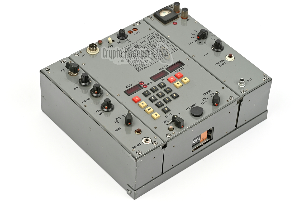
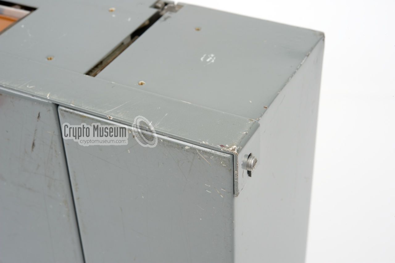
Like many other spy radio sets,
the R-394T (Strizh-T) has a modular construction,
allowing the individual modules to be hidden separately. It also allows
simple replacement of a module in case of a failure. Like its brother,
the R-394KM, it consists of three functional modules:
a receiver (RX) on the
left, a transmitter (TX) on the right
and a control unit at the centre.
The Control Unit, or Digital Storage Unit (DSU),
contains the burst transmitter and the burst
receiver, but also the individual RX and TX synthesizers.
Without the DSU, the other two modules can not be used.
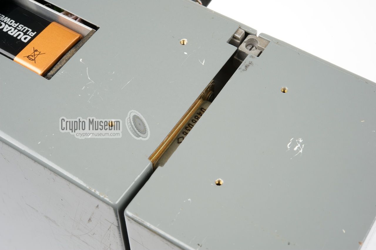
The three modules are interconnected via the
large connectors towards the
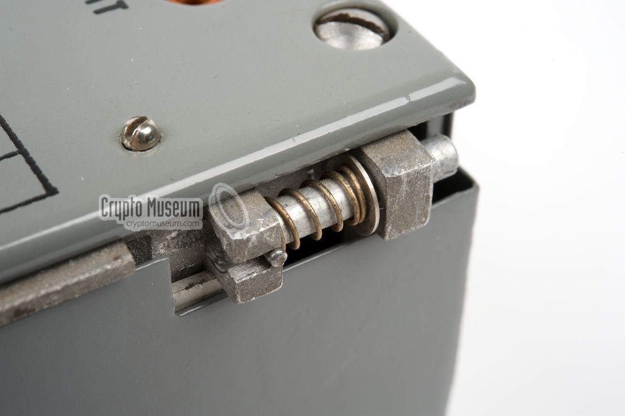
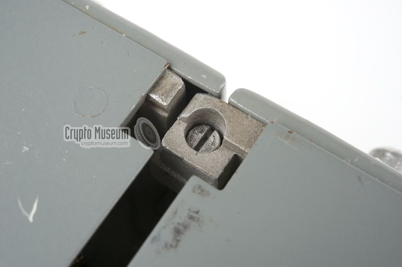
front of each unit. An ingenious
spring-loaded clamp mechanism holds
the units together. Each module has two such clamps just below the
control panel: one towards the front and one towards the rear.
The units can be separated again by pushing the spring-loaded
clamps inwards with a screwdriver.
|
|
The Digital Storage Unit (DSU) is at the heart of the R-394T radio station.
It contains individial digital synthesizers for the transmitter and the
receiver, allowing split-frequency operation between 1.5 and 13.5 MHz.
The DSU also contains an automatic digital message centre. Each feature
has its own 5-digit red display, but the black numerical keypad is used for
for all three.
|
The DSU allows 203 groups of
five numbers each (typically called datagrams) to be stored in its
internal memory. Once the connection with the spy centre has been established,
the datagrams are sent at very high speed (burst) in order to
reduce the time on the air and hence minimize the risk of interception
and detection.
The DSU is also capable of receiving burst transmissions, typically from
the spy centre, fully automatically,
and can store messages in its internal message, so that they
can be read later through the leftmost 5-digit red display.
|
|
|
|
In order to retain
the data in the DSU's memory, a 9V backup battery
has to be installed through a rectangular hole
at the front of the DSU. This is different from the regular R-394KM.
The DSU shows the current state of technology in the
Soviet Union (USSR) in the early 1980s.
It shows that the Russians had abandonned valve-based
technology in favour of transistors and integrated circuits (ICs)
and that they had embraced digital solutions.
Despite its compact dimensions, the DSU contains no less than 120
integrated circuits (ICs)!
|
|
The leftmost module is the receiver. It is connected to the left of the DSU
and is a double-superheterodyne receiver with the same frequency
range as the transmitter (2-15 MHz). The frequency is adjustable in steps
of 1 kHz and the intermediate frequencies are at 140.5 MHz and 500 kHz.
|
The type of modulation is set with a 3-position selector at the top.
The receiver is suitable for AM (A3), CW (A1) and A2.
The latter (A2) is for the reception
of digital (telegraphy) signals that are modulated onto a sub-carrier.
For the reception of normal morse code signals, the middle setting (CW or A1)
should be used [2].
Below the modulation selector is the adjustment for the Beat Frequency
Ocillator (BFO) that is used for making CW signals audible. Below the
BFO are the LF audio adjustment (volume), the antenna adjustment and
the HF band selector.
|
|
|
The middle display at the centre of the DSU is used for the receiving
frequency in kHz. This display is marked 'REC'. After switching on the
radio, with the power switch at the top center of the DSU, set the MODE
selector (bottom right of DSU) to REC. Next set the band selector to
the desired frequency range. The following ranges are available:
2 → 3 MHz,
3 → 5 MHz,
5 → 8 MHz,
8 → 13 MHz
The RX frequency can be set by holding down the K-button below the
display briefly, pressing the red C-button to clear the synthesizer and
then (whilst holding down the K-button), typing 5 digits on the key pad.
When finished, release the K-button. The display will now be blanked again.
Please note that 4-digit frequencies, e.g. 7035 kHz need a leading '0'
as shown here:
07035
10150
12887
Now press and hold the unmarked TUNE button
(just above the earphone socket)
and tune the antenna adjustment of the receiver (ADJ ANT) for a
maximum reading on the meter. And finally the volume knob should be
used to ajust the audio level of the earphone to an appropriate level.
|
|
The rightmost module is the transmitter. It is connected to the right of
the DSU and delivers approx. 15W PEP. Manual telegraphy, using the built-in key
or the numbers 0-9 on the key pad is possible in A1A modulation, (CW) but for
a burst transmission Phase Modulation (PM) is used. This allows a transmission
speed of 835 numbers per minute (equivalent to 167 datagrams).
|
Before using the transmitter, a suitable antenna wire length should be
selected from the table on the DSU. For example: when transmitting on a
frequency of 5125 kHz, the antenna wire (ANT) has to be 8 metres long,
whilst the matching counterpoise (GND) should be 12 metres long.
Next, clear the existing transmission frequency by pressing the C-button
under the rightmost display and enter the required frequency on the key pad,
e.g. 05125. Use the K-button to check the frequency on the display.
You may also hold down the K-button while entering the frequency.
|
|
|
Set the Antenna Matcher to the required position as indicated in the
table on the DSU. For example: for a frequency of 5125 kHz, the
Antenna Matcher (STEP) should be set to '8'.
Now select the required modulation type with the MODE selector at the
bottom right of the DSU. For burst transmissions, it should be set to
FM, which is actually Phase Modulation (PM).
Press and hold down the morse key and adjust the FINE knob for a
maximum reading on the meter. Then release the morse key.
→ On this version of the radio, an external morse key should be used.
When using Strizh for manual telegraphy (morse code), connect an external
key to the CINCH socket on the transmitter (KEY) or the EXT socket
on the DSU, and set the MODE selector on the DSU to CW (A1).
On the military version of the radio, the R-394KM,
the internal morse key on the transmitter can be used for this.
Mode A2 is used for high-security burst transmissions, in which the
signal is modulated onto a sub-carrier.
The push button (CONTROL POWER) can be pressed to check the battery
voltage. It should put the needle of the meter somewhere in the green area.
|
|
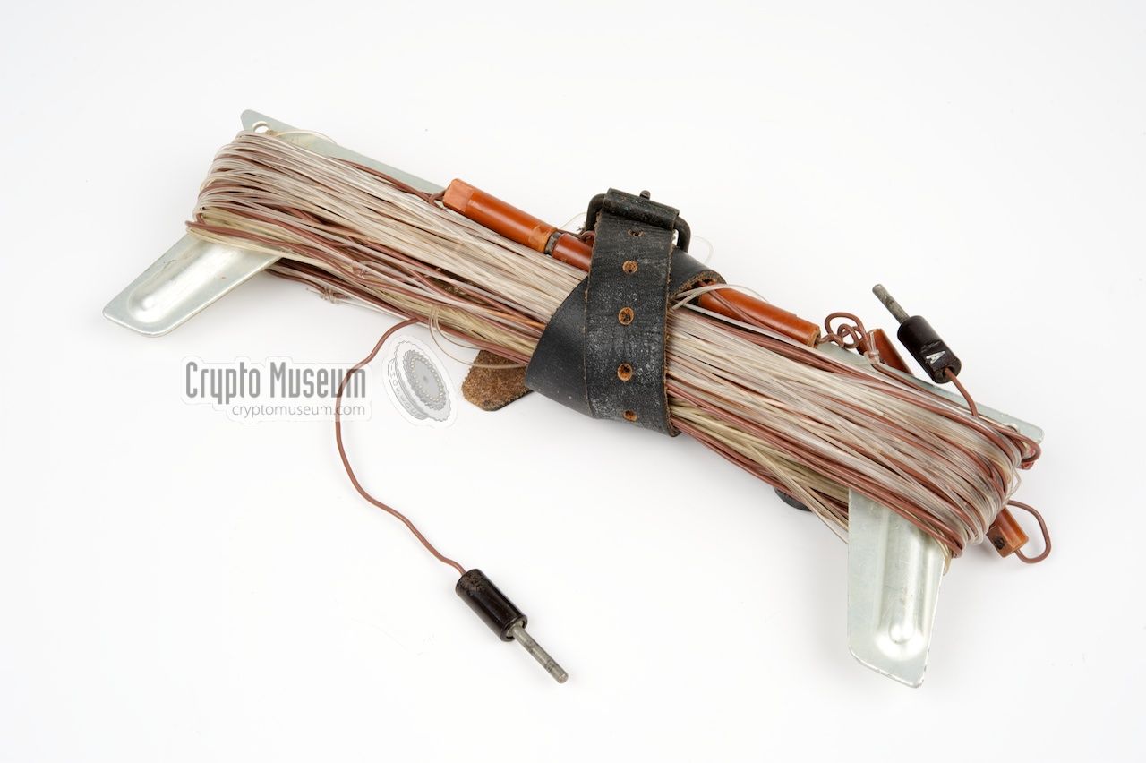
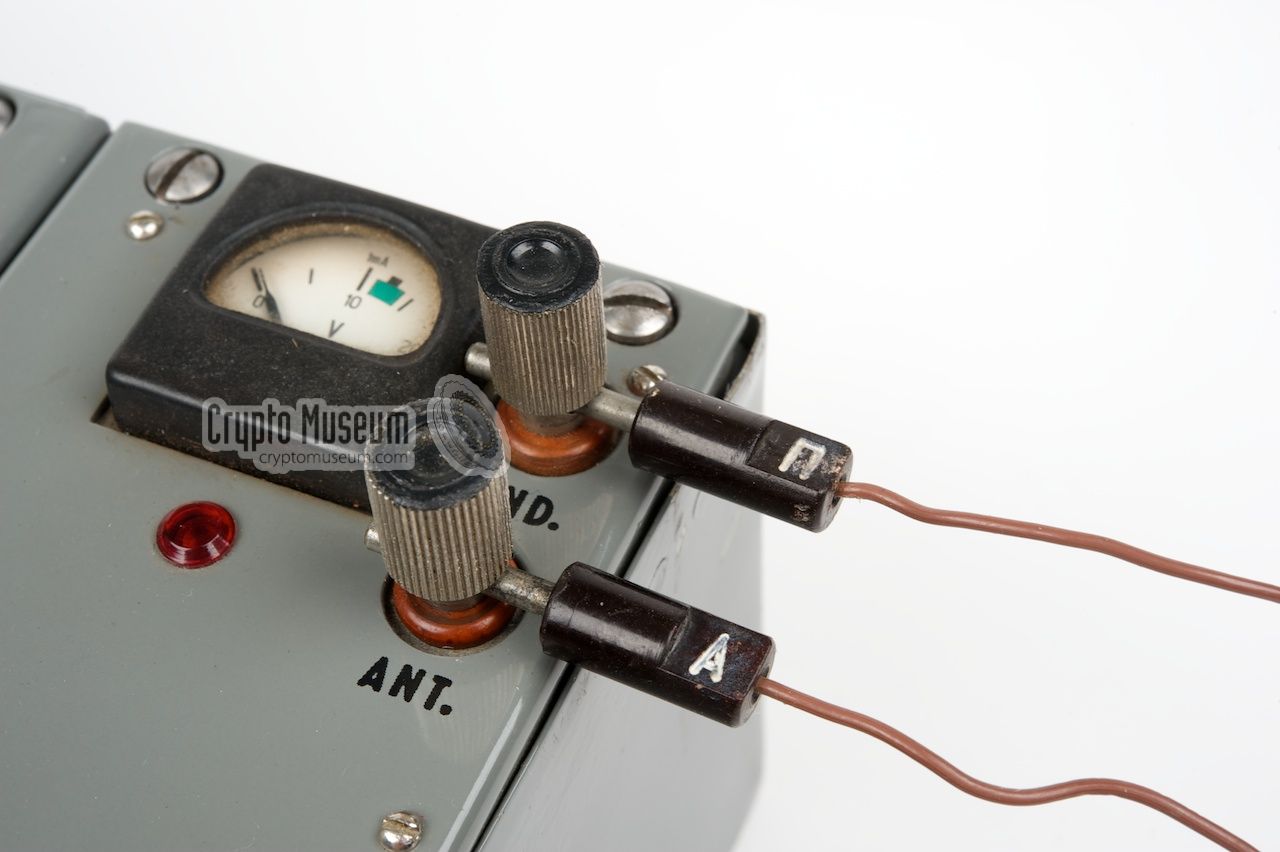
Like most HF radio sets, Strizh is best used with a wire antenna.
Depending on the selected operating frequency, a wirelength of 6 or
8 metres was used and a counterpoise of 4, 6, 8 or 12 metres.
A table, printed on the control panel of the DSU, shows which wire
lengths to use.
|
The two wires were
connected to the two screw-terminals at the top
right of the transmitter, to the right of the meter. The upper connector
is for the counterpoise wire (GND) whilst the lower one is for the antenna
(ANT). When transmitting, a small red light, just below the meter,
gives an indication of the antenna current.
The length of the wires has been choosen carefully, so that the standing
wave ratio of the transmiter can be matched easily by the built-in antenna tuner.
Again, the table on the DSU is used to select the correct tuner preset.
|
|
|
The table dictates the setting of the STEP selector on the transmitter,
for any given frequency. For example: when transmitting on a frequency
of 7035 kHz, the STEP selector should be set to 9. The FINE knob is then
used to adjust the transmitter for maximum power output. Select the desired
transmission mode (e.g. CW), activate the transmitter by holding down the
external morse key and ajust the FINE knob for a maximum reading on the
meter. Then release the key.
|
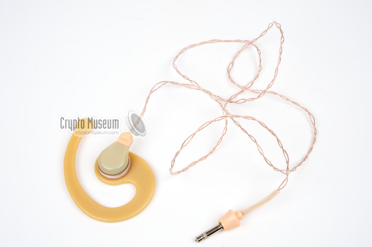
Unlike the military R-394KM, which uses a Russian military pair of headphones,
Strizh has been converted for use with standard domestic earphones with a 3 mm
jack at the end. The one shown here was made in Russia in the 1980s and came
with a standard Western 3 mm jack.
When the operator lost his earphone or when it got broken, he would be able
to buy a standard earphone from a local store whithout attracting any
attention. The earphone is suitable for both the left
and the right ear, as the plastic clip can be reversed.
|
|
|
|
Strizh should be powered by a 12V DC source that can deliver 5A.
Although it is possible to use an external power supply unit,
the radio was commonly driven from the battery of a car. When the spy
had to send a message to the spy centre in the homeland, he would
drive to a quiet spot, e.g. in a forest, put up the antenna,
connect the radio to the car battery and deliver the message.
|
In order to save time, he might have entered the (pre)coded message
in the memory of the DSU at home. This is why the DSU has a backup battery.
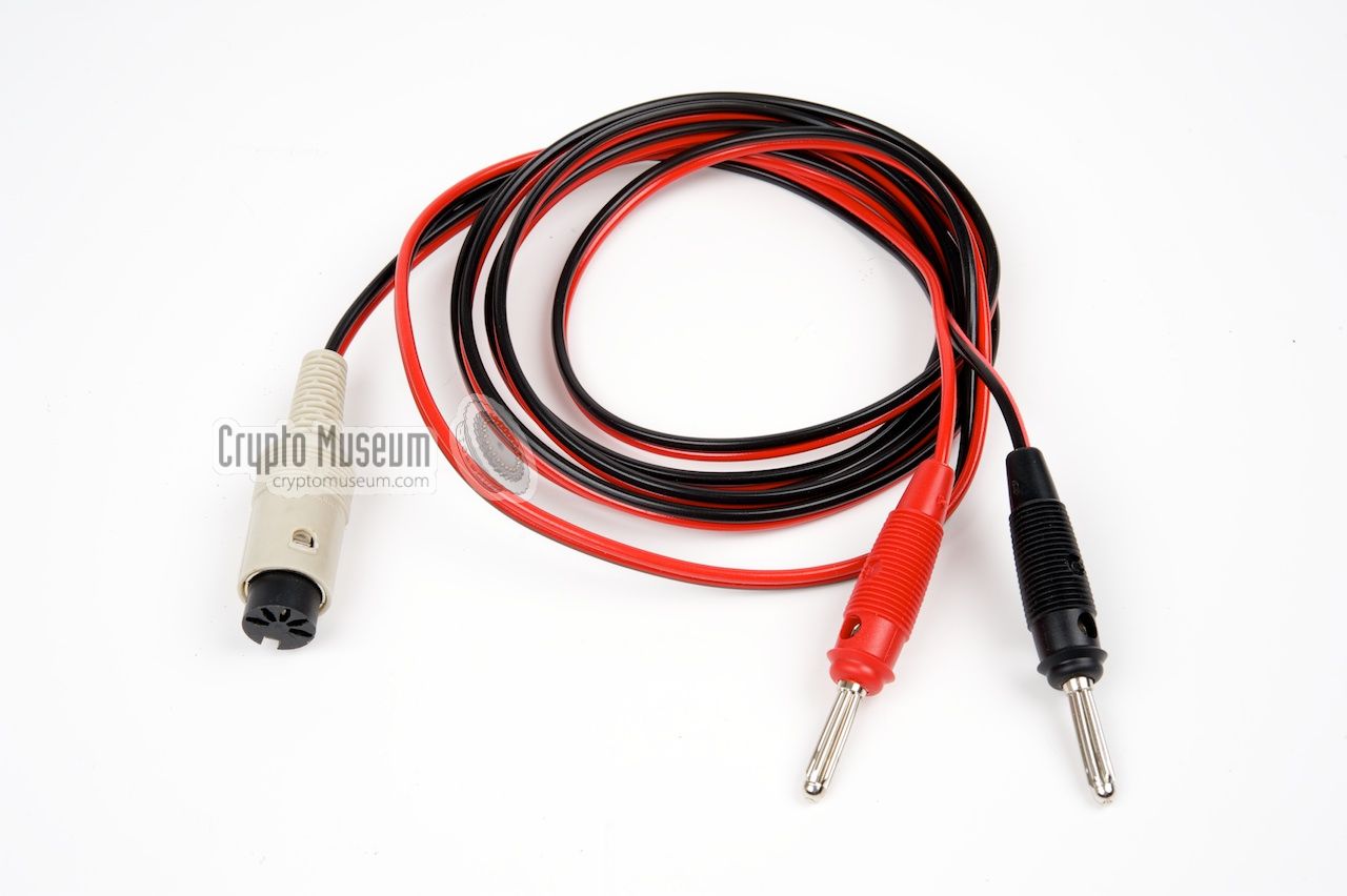
As the battery cable might break or get lost, Strizh was equipped with an
8-pin DIN power socket,
rather than a Russian military one.
It allowed the spy to buy a new connector from a local electronics store.
The cable shown here was probably made at a later date. As the former owner
probably couldn't find a suitable 8-pin DIN connector, he used a 5-pin one
and broke away the remaining three pins from the socket.
|
|
|
The original cable would probably have had a cigarette-lighter plug in place of
the two banana-type plugs shown above, or ultimately two battery clamps,
allowing it to be connected directly to the car battery. As 12V is the most
common voltage in domestic cars world-wide, Strizh can be used directly.
For the same reason, older spy radio sets, such as the
R-350 and the
R-354,
were powered by 6V DC, which was a common voltage in the cars of
the 1950s and 60s.
➤ Pinout of the DIN socket
|
|
Unlike the military variant, the R-394KM,
Strizh is not housed in a transit case.
Instead, its casing is constructed in such a way that it could be built
inside virtually any type of concealment, for example a common briefcase
that would not attract unnecessary attention when carried around.
|
When this unit was (re)discovered in 2014, it was stored inside a green
aluminium transport case that was originally used for a military
9S13 (Russian: 9С13) homing device. The radio set fits tightly inside this
case, but the lid has been bulged somewhat in order to accomodate the knobs.
The top lid of the case is rubber-sealed.
It is unlikely that Strizh was originally stored inside this case.
Carefully hiding the fact that it is a Russian device (by putting English
text on the front panel) and then storing it inside a case with Russian
markings, doesn't make any sense.
|
|
|
Furthermore, the case has no space for the accessories, such as the
headphones, the power cable and the antenna wires. On the other hand,
the case might have been used to protect the radio when it was stored
for longer periods of time, e.g. as part of a cache. In that case,
the accessories might have been stored in a separate container.
If you know more about this, please let us know.
|
|
The transceiver consists of the following building blocks:
|
|
This is the largest of the three units that is physically placed between
the transmitter (block 1) and the receiver (block 2). Although it is called
the synthesizer, it is much more than that. It contains the internal power
supply unit (PSU), a keypad and three displays, and provides the tuning
signals for the receiver and the transmitter. Furthermore it contains
the Storage-Keying Device (NMU)
that allows messages to be stored in its
internal RAM and sent at very high speed.
|
- 2-01 - Reference oscillator (10 MHz)
- 2-02 - Analogue board (synthesizer)
- 2-03 - Display and keypad board
- 2-04 - Logic board
- 2-05 - PSU
- 2-06 - PLL (phase detector)
- 2-07 - NMU (see below)
|
|
Inside the synthesizer section (block 2) is a digital circuit that is
provided as a closed metal block with a large connector at one end.
This block is marked SECRET and is known as NMU
(Russian: НМУ), which stands for:
Накопительно-манипулируюшего
устройства
(Storage-keying device).
Inside the NMU are five circuit boards, marked A1 thru A5, which contain
the following circuits:
|
- A1 - Tone Telegraphy keyer (TT)
- A2 - Morse keyer (CW)
- A3 - Address decoder and RAM
- A4 - Pulse distributor
- A5 - Phase Telegraphy keyer (FT)
|
|
The device has a male 8-pin 262°
DIN receptacle for connection of the external 12V DC power source. It replaces the Russian 4-pin male socket of the
military R-394KM. Below is the pinout when looking
into the DIN receptacle. Note that a 5-pin variant 1 would have been sufficient.
|
- 0V
- unused
- +12V
- 0V
- +12V
- unused
- unused
- unused
|
|
-
Our our device, pins 6, 7 and 8 have been removed,
so that a regular 5-pin female cable part can be fitted.
|
A 10-pin expansion connector is present at the center of the DSU,
between the MEMORY and MODE selectors. This socket is sometimes protected
by a black plastic cap and is intended for the connection of
additional equipment such as an external morse keyer. It allows the transceiver
to be partly remote-controlled by the external device.
The connector has the following pin-out:
An external key can be connected between KEY and GND. Please note that the
radio has two KEY inputs: one used for AM (amplitude modulation)
and one for PM (phase modulation, here called 'FM').
Also note that the pin-out of this socket is different from the same socket
on the earlier R-394K radio. Connectors for this socket are
difficult to obtain.
|
-
This contact is NOT wired on most Strizh/R-394KM units. When wired, it
provides a clock signal for an external keyer. In A2 mode, the clock signal
is 100 Hz. In FM mode it is 250 Hz.
|
WARNING — connecting the wrong type of accessory may cause permanent damage.
On the version of Strizh featured on this page, this socket was probably unused
as a separate key input is available on the transmitter.
When the device was found, the socket was covered with a black plastic cap.
Device Spy radio set Purpose High-speed agent communication Origin Soviet Union (USSR) Year ~1983 Frequency 2 - 15 MHz (actually: 1.5 - 14.999 MHz) Steps 1 kHz VFO Digital PLL Modulation AM, PM, CW, A2 Datagrams 203 groups (of 5 letters each) Power 12 - 13.8 V DC Current 0.7 A (RX) or 4.5 A (TX) Output power 15 Watt Weight 8 kg
|
|
It is difficult to determine the manufacturing date and the production
quantity of the R-394T, as the devices do not have a serial number tag.
Instead there is a label on the NMU Block (inside) with a
handwritten serial number and production date.
The following ones have been recorded:
|
| Model | S/N | Date | Location |
| R-394T/I | 300928 | 25 Oct 1983 | Private collector (Slovakia) |
| R-394T/II | 600402 | 30 Apr 1986 | Crypto Museum (Netherlands) |
|
- Radio Station R-394KM Technical Description and Operating Instructions
Full circuit description, block diagrams and wiring diagram (Russian).
IV1.106 007 TO. 1988. SECRET. Serial number 10.
➤ Drawings and diagrams for this manual
- Radio Station R-394KM Technical Description and Operating Instructions. Appendix.
Components list and circuit diagrams (Russian).
IV1.106 007 TO1. 1988.
- Block NMU (Блок НМУ) Technical Description
Circuit description and diagrams of the burst encoder (Russian).
2.082.046 TO. 1988. SECRET. Serial number: 31.
|
- Gunter Fietsch, Nachrichtentechnik der Nationalen Volksarmee
Part 2, 1996, p. 303. ISBN 3-88180-340-8.
- Wikipedia, Types of radio emissions
Overview of modulation types. Retrieved September 2014.
- Crypto Museum, Modulation, Types of radio emissions
April 2020.
- Anonymous source, Eye witness account of R-394KM found in Germany
Interview with Crypto Museum, 2009.
- Jozef Burda (OM0ASB), STRIZH Mark 2
Retrieved 8 May 2021.
- Louis Meulstee, R-394T
Wireless for the Warrier. Volume 4. Supplement Chapter 159.
January 2019.
- 'Factory-fresh' Soviet spy radio discovered in German forest
Military History, 23 April 2020.
|
|
|
|
Any links shown in red are currently unavailable.
If you like the information on this website, why not make a donation?
© Crypto Museum. Created: Sunday 27 September 2015. Last changed: Thursday, 11 December 2025 - 21:21 CET.
|
|

|
|