|
|
|
|
|

|
|
← R-353
The following instructions are based on the small
aluminium booklet
that is present in the top lid of the R-353,
with some interpretations.
It contains five pages with Operating Instructions
in 'stone-age English'
that can be used as a quick guide when putting the R-353 to work.
|
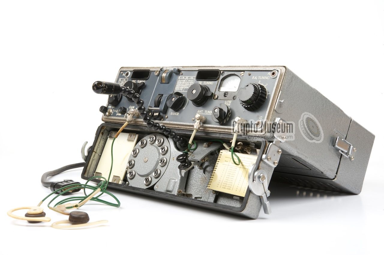
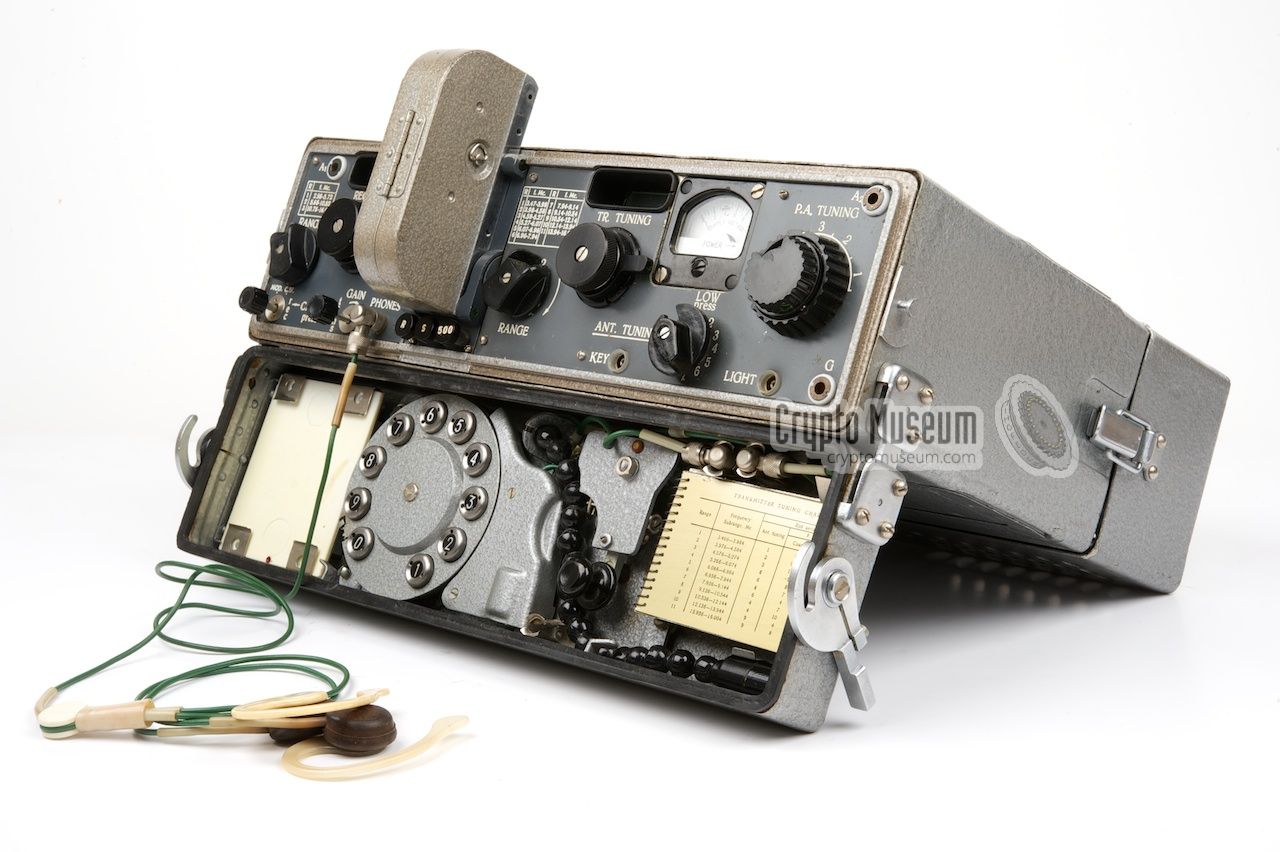
- Prepare the radio station for operation. Open the top lid and fixate
it. Connect the items in the top lid to the front panel of the R-353:
EARPHONES, KEY and LIGHT.
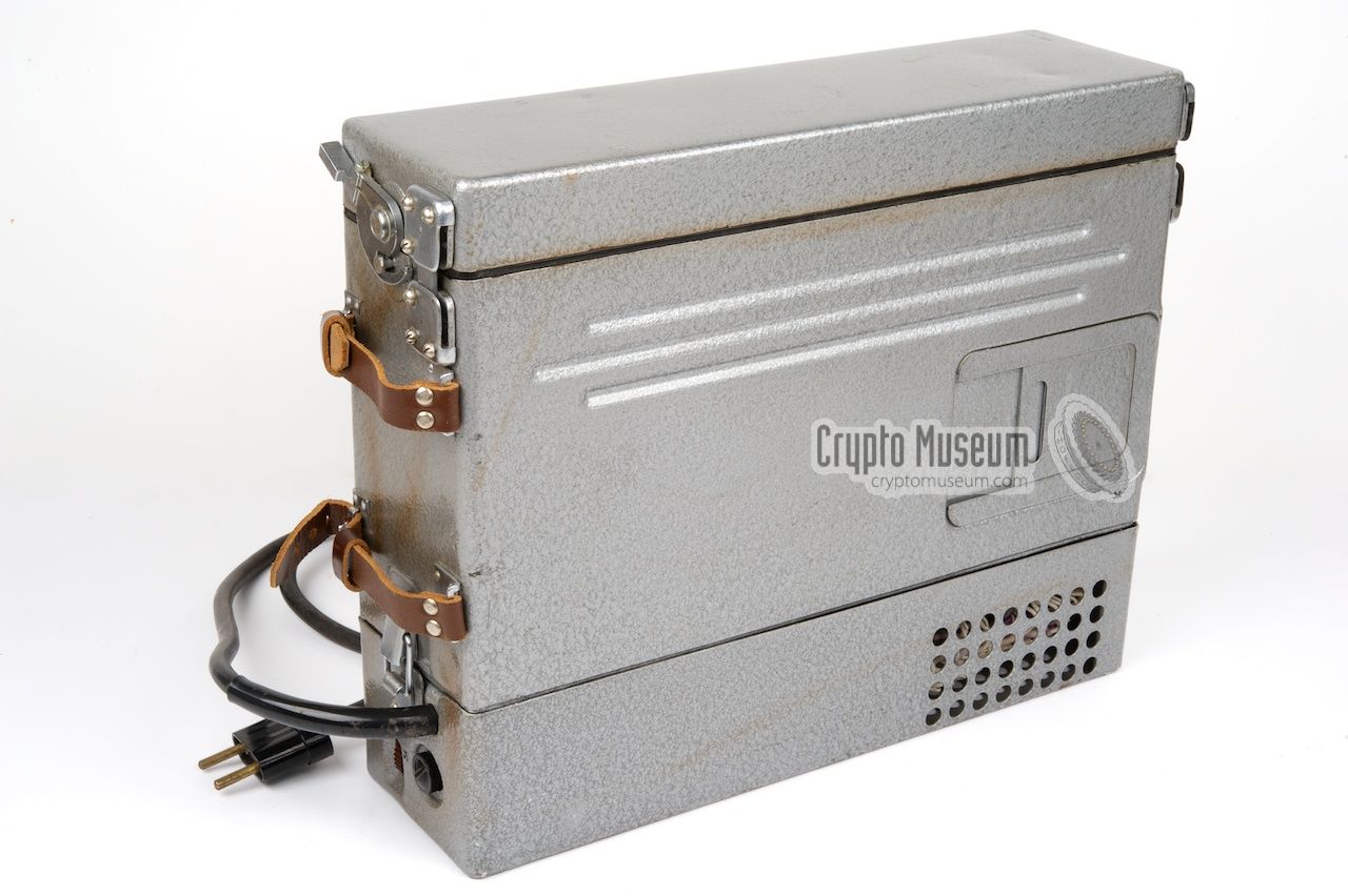
- Ensure the appropriate Power Supply Unit (PSU) is connected to the
transceiver. Connect the PSU to a suitable power source
(select the correct mains voltage)
and check the reading on the meter.
For AC, the meter should be at the upper end of
the marked sector. When using DC, the meter should be at the lower end
of the marked area.
- Arrange the aerials. Connect the receiver antenna (4m) to the socket
marked A1.
Connect the transmitter antenna (12m) to the socket marked A2
and counterpoise to socket G.
NOTE
- When operating in a vehicle, use wire G to connect socket G to the
vehicle body.
- The 5m rod antenna may also be used.
- Ensure the correct polarity of the battery connection.
- Open the ventilation holes of the transmitter
(top
and bottom).
|
- Select the desired frequency RANGE on the receiver (1-3).
- Select the desired modulation type (AM or CM) with the rotary switch
marked MOD.C.W. at the bottom left. Set GAIN to the mid-range position.
- Adjust the REC.TUNING knob to the calibration frequency closest
to the operating frequency at the centre of the scale.
- Press the receiver calibration button REC.-CALIBR. and slowly turn the
receiver fine tuning knob to find the position in which the meter shows
a minimum reading and no tones are heared in the earphones (zero beat).
Release the calibration button and match the hairline with the selected
calibration frequency marking on the scale.
- Use the REC.TUNING knob to align the desired operating frequency
with the hairline.
|
- Attach the cassette with a pre-coded message to the automatic keyer
and press the high-speed transmission button marked
250 (or 500 on some units).
Hold it down for 2-3 seconds, then release it.
- Select the desired frequency range (1-11) with transmitter RANGE knob.
- Use TR.TUNING to set the calibration frequency closest to the operating
frequency at the centre of the scale.
- Hold down the transmitter calibration button TRANS.-CALIBR.
and slowly turn the transmitter tuning knob TR.TUNING to find
a minimum reading on the meter and no tones are heard in the
earphones (zero beat). Release TRANS.-CALIBR.
and match the hairline with the calibration frequency mark.
Calibration is needed for each sub-range.
- Use TR.TUNING to align the desired operating frequency with the hairline.
- Set ANT.TUNING and P.A.TUNING to the positions indicated in the
frequency chart.
- Press and hold down LOW and adjust PA.TUNING for a maximum reading
on the meter.
- Establish a connection by pressing the S-button on the keyer (start).
- After releasing the S-button, listen for the answer signal (a series
of dots).
- When using the semi-automatic keyer, press the desired number on the
dial, rotate the dial to the end-position and release the button.
Wait for the dial to return to its initial position.
NOTE
- in order to save energy (RX only) switch off the valve (tube) filaments
of the transmitter by setting the power switch (on the side of the PSU)
to OFF and then back to ON again.
- Before starting a burst transmission at temparatures below -10°C,
hold down the 250 (or 500) button on the keyer for a minute
(without a cassette being present) to heat the keyer.
|
- Radio Station R-353 Technical Description and Operating Instructions. Part 1 and 2.
Original documentation (Russian). 0.200.018 TO/c. 1969. 184 pages.
- Radio Station R-353 Technical Description and Operating Instructions. Part 1.
Original documentation (Russian). 0.200.018 TO/c. November 1988. 59 pages.
- Radio Station R-353 Technical Description and Operating Instructions. Part 2.
Original documentation (Russian). 0.200.018 TO/c. November 1988. 126 pages.
|
|
|
|
Any links shown in red are currently unavailable.
If you like the information on this website, why not make a donation?
© Crypto Museum. Last changed: Wednesday, 16 August 2017 - 08:23 CET.
|
 |

|
|
|


