|
|
|
|
|

|
|
CIA NRP EC SRS-91 SRR-90 →
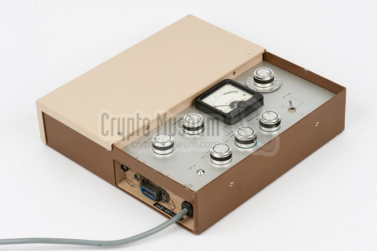
The SRR-91 had a flat rectangular design and was no higher than 60 mm,
so that it would fit nicely inside a common briefcase of the era.
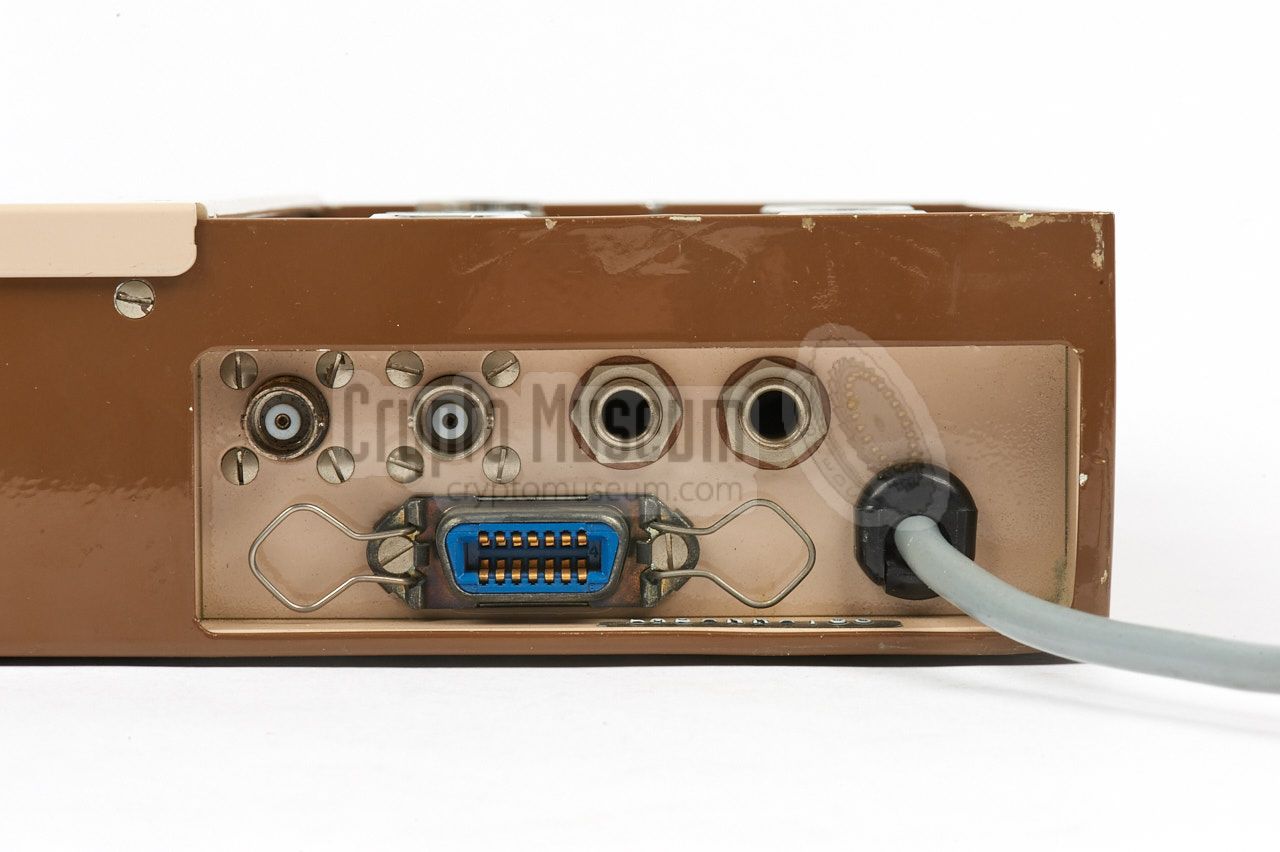
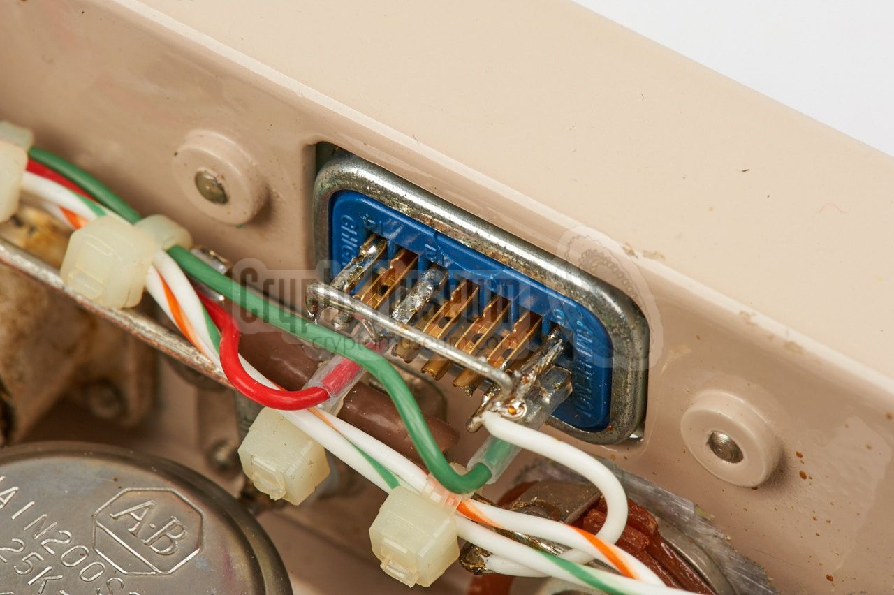
All controls are at the front half of the top panel, whilst all
connections are located at the left side. The rear half of the
receiver contains the various modules,
and can be accessed by
lifting the hinged lid
that is held in place by two screws.
The device is suitable for the reception of bugs that
use the sophisticated
Dirty Pulse (DP) audio masking scheme,
also known as the 91 scheme,
that was used by the SRT-90
and SRT-91 bugs.
|
|
|
It is also suitable for the reception of transmitters that use the
Rejected Pulse (RP) audio masking scheme,
such as the SRT-56,
SRT-56-F
and SRT-107 2 , although for these
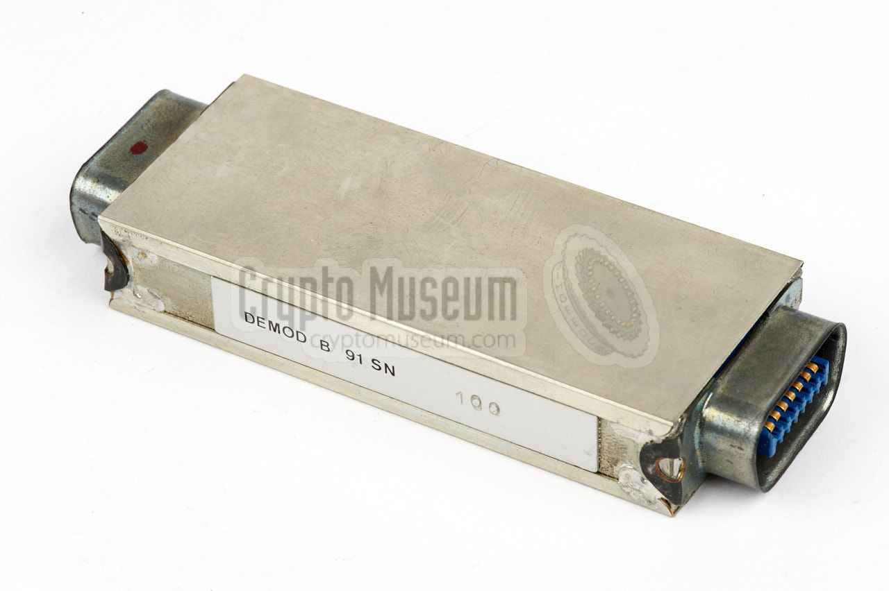
bugs, the DEMOD B plug-in
had to be installed the other way around.
For this reason the DEMOD B plug-in has a connector at either end.
The SRR-91 superseded the SRR-56 receiver,
but not the SRR-52,
as it is not suitable for transmitters with
Triple Pulse (TP) audio masking scheme,
such as the SRT-52.
The SRR-91 was developed during the course of 1973 and 1974,
with the first production devices being delivered in November 1974.
It was in production until at least 1976. About a year after its
introduction, in 1975, the SRR-91 was succeeded 3 by the more advanced
SRR-90 A/B,
that was available in two variants: a straight-up tabletop
model, and a flat one for use inside a briefcase.
➤ More about its history
|
 |
-
As part of the modification, the modules were immunized against
pulse-type interference caused by the ignition of cars and motor cycles.
-
For the reception of the SRT-107,
the SRR-145 down-converter is
required as well. This is also the case for the high-band version
of the SRT-56.
-
Although its model number suggests otherwise,
the SRR-91 was developed and produced about one year
earlier than the SRR-90.
The reason for this is the fact the SRR-91 was initially known as
the SRR-91 Mk I, whilst the enhanced version — to be produced
later — would be the SRR-91 Mk II. However, when the SRR-91 Mk II was
ready for release, the CIA decided to rename it SRR-90.
|
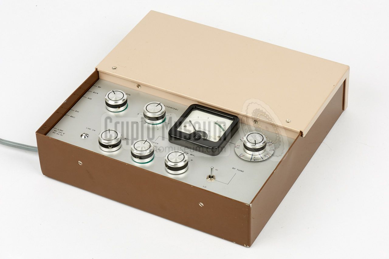
The SRR-91 is designed for installation in a common slimline Samsonite
executive style briefcase. As it consumes little power and does not
produce heat, it can be operated safely from inside the briefcase.
Under normal circumstances, the hinged lid over the modules, that are
installed in the rear half of the unit, remains closed.
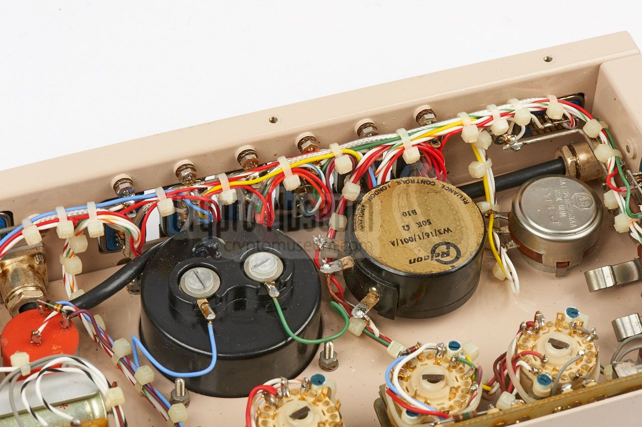
The front half contains the controls as shown below.
Prominently visible is the large square indicator (meter) which is used for
several measurements, controlled by the function selector at the bottom
centre. To the right of the meter is the tuning knob, which has two scales:
one for the LO and one for the HI band, selectable with the toggle
switch at the bottom right. The unit is switched ON with the Power selector
at the bottom left.
When tuning into the signal of a bug, the pulse locking knob should
be tuned for the best quality of the reproduced sound, using the indicator to
find the optimum. By default, the receiver was suitable for the reception
of DP-masked bugs,
like the SRT-91,
but by installing the DEMOD B plug-in the other way
around, it was made compatible with
RP-masked bugs
like the SRT-56.
|
|
The SRR-91 is suitable for receiving and decoding the following
transmitters:
|
At the heart of the listening post is an SRR-91 receiver.
It is just 6 cm high, allowing it to be fitted inside the thinnest
Samsonite briefcase.
The receiver is fully modular, so that it can be repaired in the field
within minutes, simply by swapping some of the modules. This also allows
the receiver to be adapted to different
masking schemes, although
it is doubted whether this was actually done, as it was soon superseded
by the more flexible SRR-90 receiver.
|
|
|
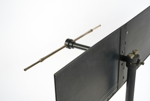
A suitable directional antenna for the SRR-91 listening post (LP)
is the SRN-9-L, or the later SRN-9. It offers a gain of 7 dB and is
in fact an adjustable dipole on a horizontal boom (which acts as a
balun), mounted in front of a reflector.
The antenna can be disassembled completely, and the reflector plane
can be folded at the centre, so that the entire unit can be stored inside
a regular suitcase, along with the SRR-91 receiver and its accessories.
➤ More information
|
|
|
The SRR-91 has two audio outputs: a fixed one for connection of a recording
device, and an adjustable one for connection of a pair of headphones.
Virtually any type of headphones with an impedance of 600Ω can be
used.
It was typically used with American military headphones of the era, such as
the one shown in the image on the right.
|
|
|
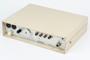
The frequency range of the SRR-91 (260 - 400 MHz) 1 could optionally be
enhanced with the 1300 - 1600 MHz band, simply by inserting the SRR-145
down-converter shown on the right,
between the antenna and the receiver's input.
This was necessary for receiving
SRT-56 units that were
equipped with a high-band SRK-145 RF module. It was also needed for the
reception of the SRT-107 transmitter.
➤ More information
|
|
|
When using the SRR-145 down-coverter shown above,
the existing SRN-9 listening post antenna has to be replaced by
one that is suitable for the 1300 to 1600 MHz frequency
range.
The SRN-55 is a flat stacked-dipole antenna that covers the entire
range and offers a gain of approx. 17.5 dB.
➤ More information
|
|
|
|
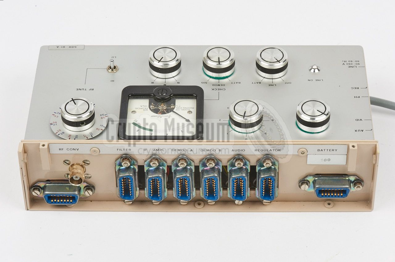
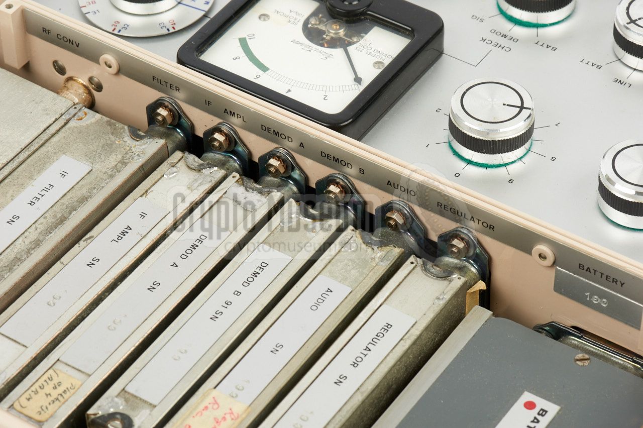
Each module should be installed in a dedicated slot of the mainframe,
as indicated by the name that is
printed above each socket.
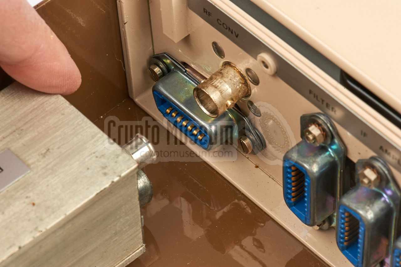
The modules have a rectangular shape and have a connector at one of the
short sides that mates with the socket on the mainframe.
Eight modules are present:
|
- RF Converter (tuner)
- Filter
- IF Amplifier
- Demodulator A
- Demodulator B ← Interchangable
- Audio
- Regulator
- Battery
|
|
The fifth module (DEMOD B), is the only one that has a connector at either
end, allowing it to be installed the other way around. This was done to make
the device compatible with both
RP audio-masking (56)
and DP audio-masking (91).
Only one 1 audio-masking scheme is supported, with the one readable on the
label being the one that is in use. Installing the module the
other way around, selects the alternative scheme.
Other masking schemes could be supported by issuing replacements for the
DEMOD B module, although in practice this never happened. 2
|
|
|
-
The later SRR-90 receiver
selects automatically between RP and DP masking.
-
Modules for alternative masking schemes were developed for the later
SRR-90 receiver however.
|
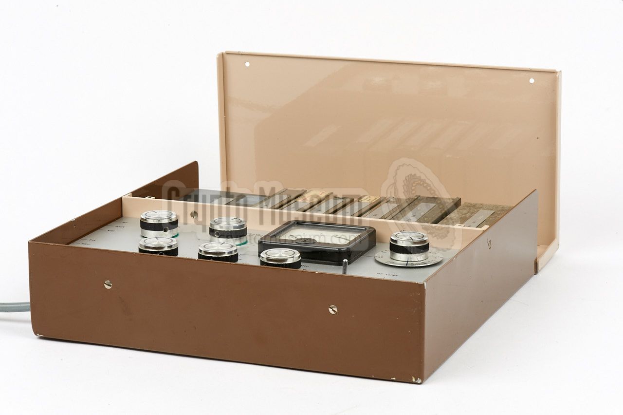
The rear half contains the actual receiver which consists of
eight plug-in units, or modules,
each of which is installed in a dedicated slot at the
rear of the mainframe.
This section is covered by a hinged aluminium lid that is
held in place by two screws that are inserted from the top.
The wiring for each module is unique, which means that a module can
only be used properly when it is installed in its own slot, as identified
by the name that is printed above each socket. Note that the modules are
not compatible with those of the early prototypes, as shown below.
|
|
|
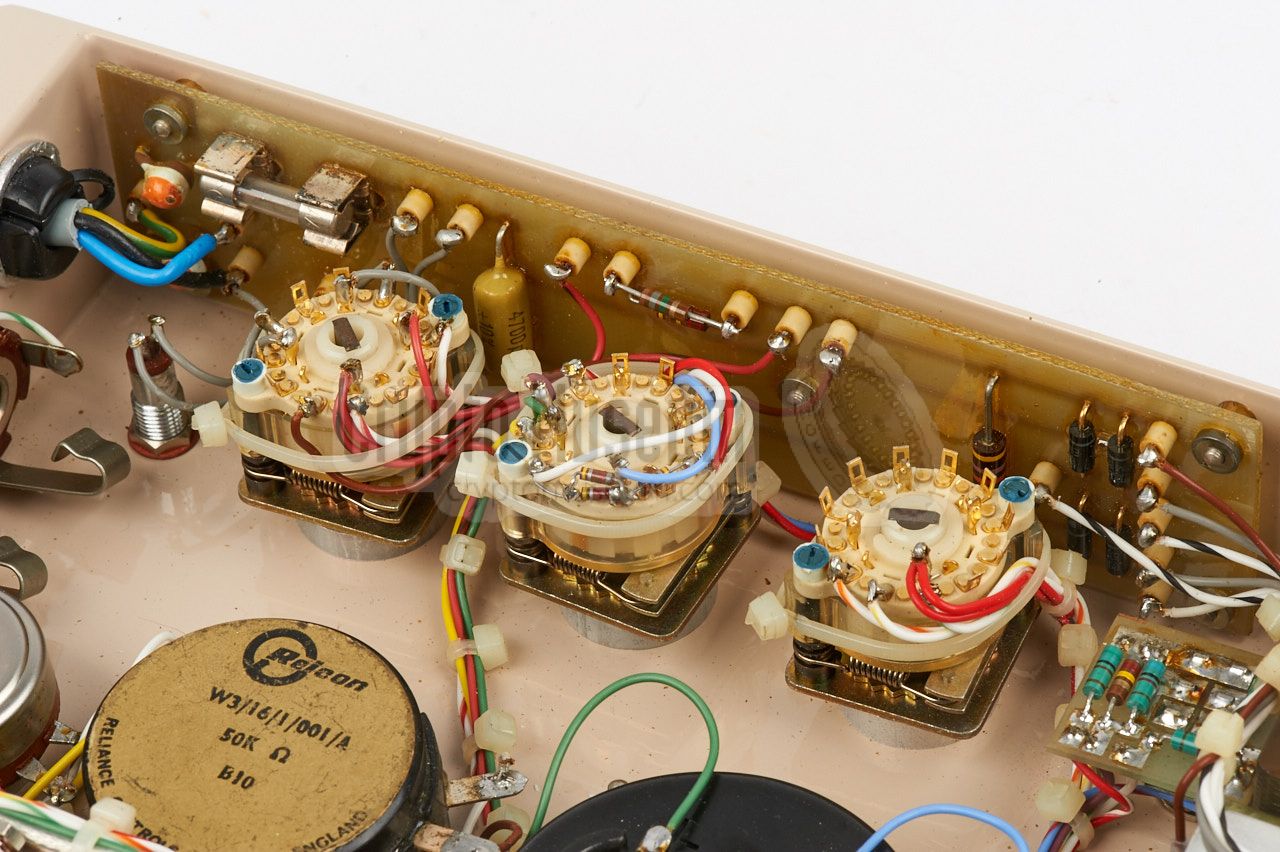
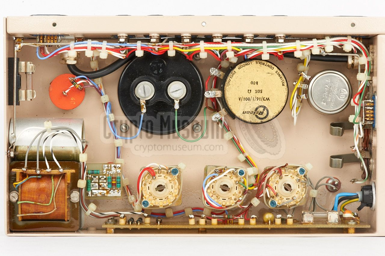
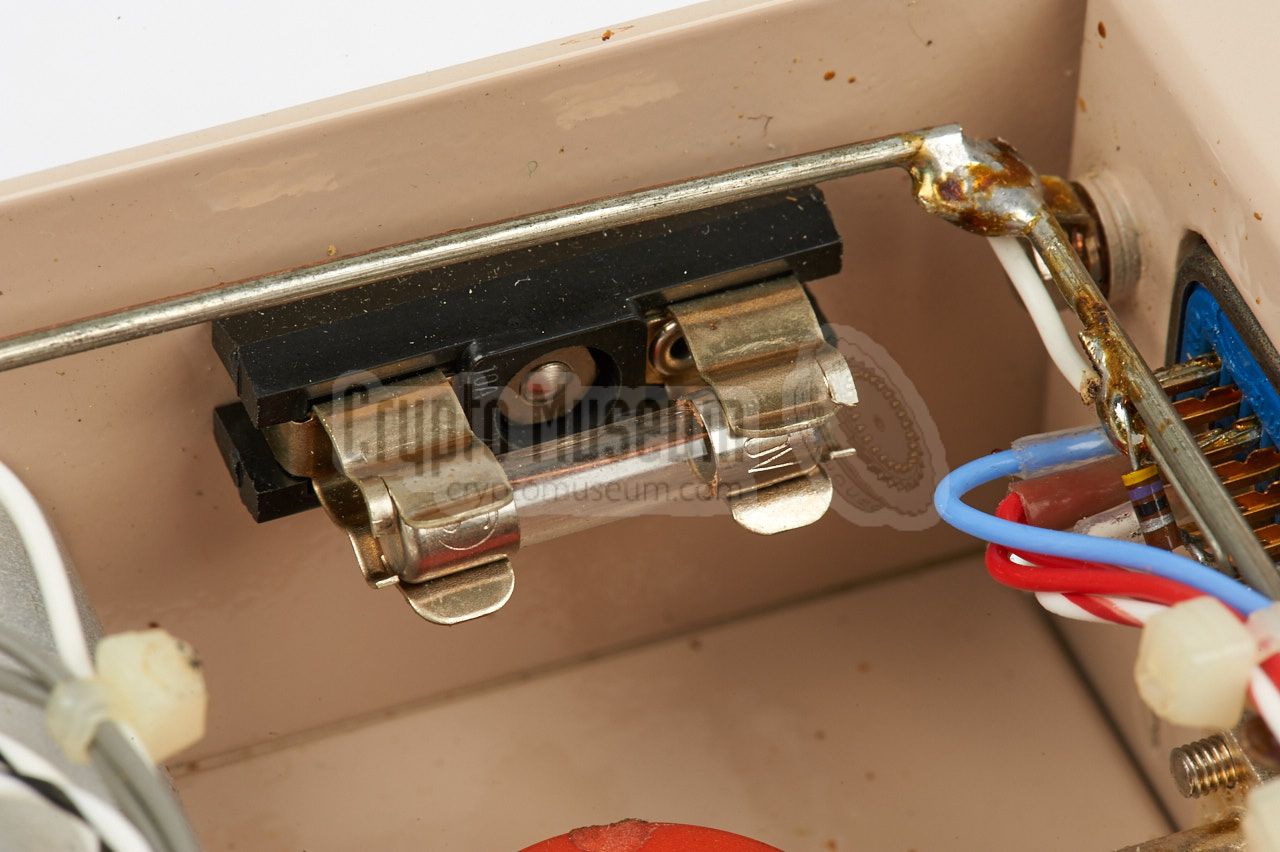
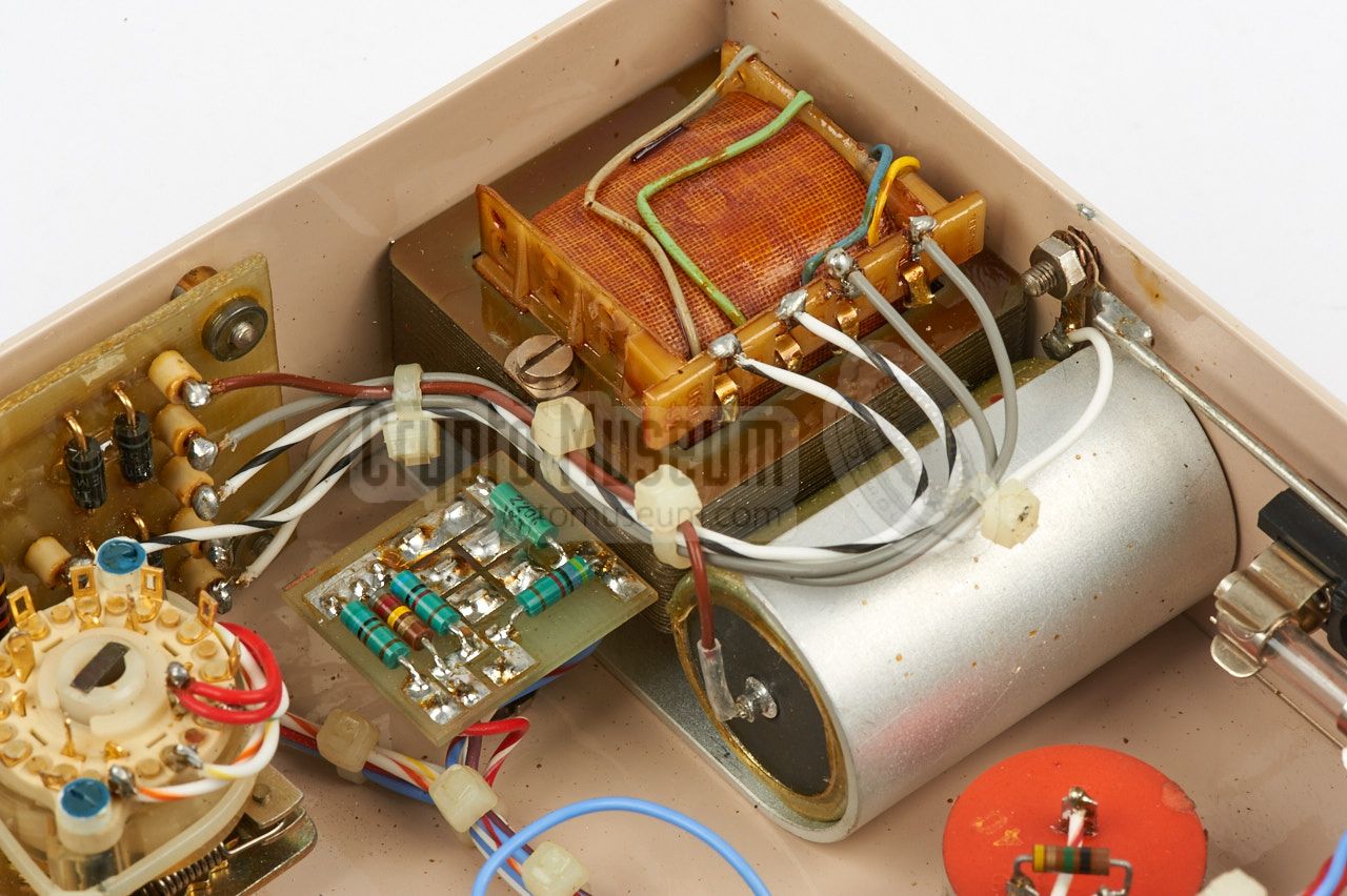
The SRR-91 is extremely well built, using only first-class components and
wiring. The circuits inside the plug-in modules are covered in
a conformal coating, in order to protect them against the environment.
As a result, the unit featured on this page still works after 25 years of
storage.
|
|
The first concepts for the SRS-91 family of devices,
date back to 1968, with the conception of an early variant of the
Dirty Pulse audio masking scheme.
After several tests and improvements,
the first SRR-91 prototype, shown in the image below,
was delivered to the CIA in March 1973.
|
At that time, the modules were still housed in plain uncoated brass
enclosures, which were identified with coloured dots rather than with
descriptive names.
The prototypes were used by the CIA to evaluate the modular concept
and test the SRS-91 system (i.e. the SRR-91 receiver and the
SRT-91 transmitter) under field conditions.
Although the receiver passed all tests, there were several recommendations
and request for further features. Some of these suggestions made it into
the final product, resulting in a number of changes in the wiring of the
slots.
|
|
|
As a result of this, the modules of the prototype version can not be
used in a production device and vice versa. A second evaluation candidate
was released and approved in November 1974,
immediately followed by full-scale production
of the SRR-91-Mark I a month later in December 1974.
In May 1975, following a modification, the SRR-91 Mark I was renamed
SRR-91-A.
The recommendations and requests that did not make it into the final design,
were implemented in its successor, the SRR-91 Mark II
(later renamed SRR-90), that was already in the early stages of its
design. The first prototypes of the SRR-90
became available in November 1974 and full-scale production started in
late 1975. It would become one of the most successful products.
➤ More about the SRR-90
|
- Manual for SRR-91-MK I receiver
CM302500/A. November 1974 (draft).
- Manual for SRR-91-A Receiver
CM302500/B. May 1975.
|
- NRP/CIA, Collection of documents related to SRR-91
Crypto Museum Archive, CM302500 (see above).
- NRP/CIA, Collection of documents related to AGC ignition interference
Crypto Museum Archive, CM302626.
- NRP, Study of Further SRS-91 Developments
October 1973, Crypto Museum Archive, CM302629/F.
|
|
|
|
Any links shown in red are currently unavailable.
If you like the information on this website, why not make a donation?
© Crypto Museum. Created: Saturday 06 May 2017. Last changed: Wednesday, 05 November 2025 - 11:40 CET.
|
|

|
|
|