|
|
|
|
|

|
|
← Easy Chair CIA NRP
In 1971, following a series of studies into the usabilty of the
newly allocated frequency bands 4, 5 and 6 (1000-1900 MHz) 1
for their covert listening devices (bugs),
the CIA
decided to move the operating frequency of some of their
existing bugs to Band 5 (1300-1600 MHz).
This band is also referred to as the 1500 MHz band.
The SRR-145 converts the new 1300-1600 MHz frequency range down
to the old 240-470 MHz range, so that any
covert listening devices (bugs)
operating on 1500 MHz, can be received and decoded on existing
CIA surveillance receivers.
|
|
|
The SRR-145 was developed during the course of 1970/1971, with the first
prototypes delivered in February and June 1971. After several improvements,
it was ready for production in November 1972. The SRR-145 had a long life
cycle, as it was used with all known NRP surveillance receivers.
|
-
Not to be confused with the regular definition of UHF Band V.
The band allocation numbers used here, are internal CIA designators.
|
The SRR-145 was initially designed for use in combination with
the existing SRR-52
and SRR-56
surveillance receivers, but it
was later also used with the
SRR-90
and SRR-91 models.
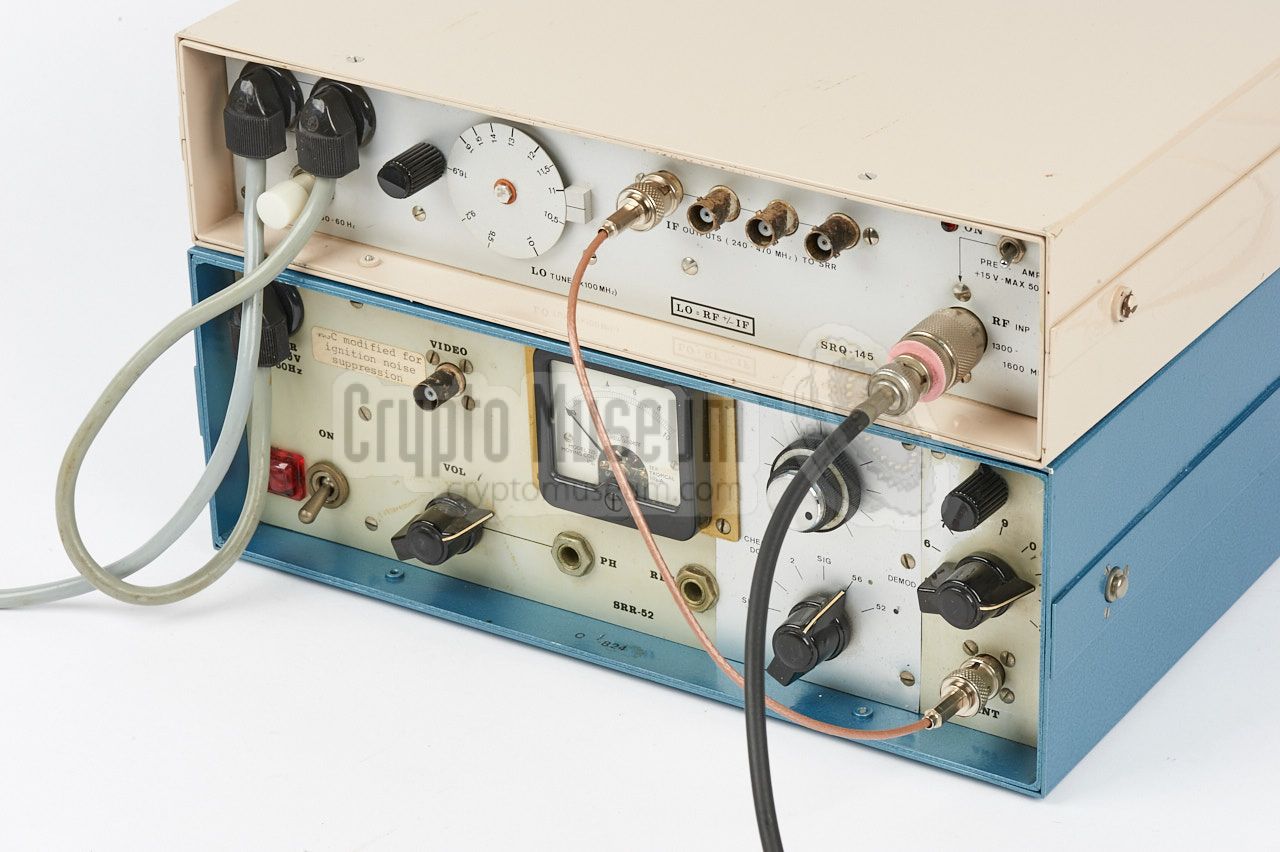
The image on the right shows the SRR-145 on top of an
SRR-52 receiver,
which has the same width. Mains power is looped via
the SRR-145, so that only one wall socket is used. A short
coaxial cable connects
one of the IF outputs to the RF input
of the SRR-52 follow-on receiver.
Later receivers, like the
SRR-90
and SRR-91, were commonly
placed on top of the SRR-145.
|
|
|
|
The SRR-145 made the above receivers compatible with the following
bugs:
|
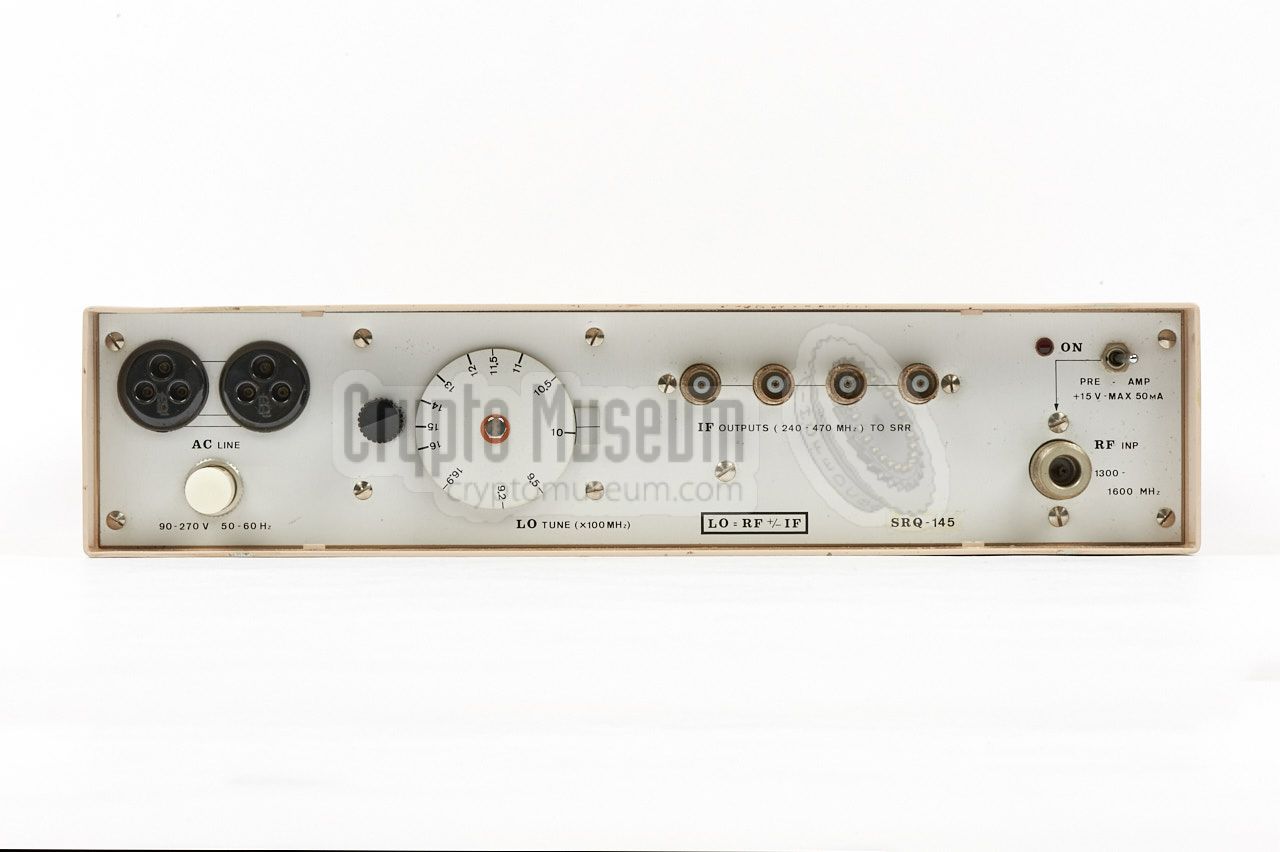
All controls and connections of the SRR-145 are located at its
front panel, which allows the device to be used in horizontal
as well as vertical position. A suitable Listening Post (LP)
antenna, such as the SRN-55,
should be connected to the
N-type socket
at the bottom right. It is powered from the 90-240V
AC mains, which should be connected at the top left.
An extra socket
is available for looping the mains power to the
follow-on receiver, so that only one wall socket is needed.
The Local Oscillator (LO) of the SRR-145 is adjustable with the
frequency tuning knob, so that the coversion point can be chosen
conveniently for least interference and optimum signal/noise ratio.
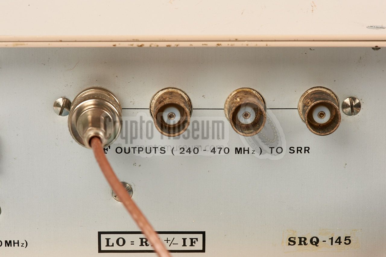
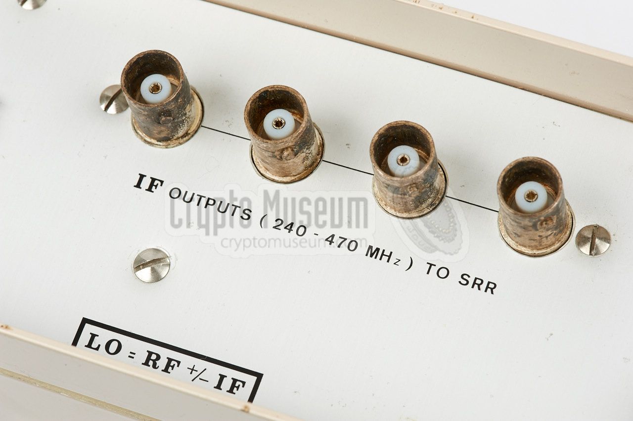
Four independent IF outputs are available at the front panel,
allowing the connection of up to four follow-on receivers,
each of which can be used for the reception of a
single 1300-1600 MHz bug.
|
The block diagram below shows the basic operation of the SRR-145,
which is pretty straightforward. At the top left is the LP antenna,
for which commonly an SRN-55
with a gain of 17.5 dB was used. After filtering the antenna signal
in a very sharp bandpass filter, it is mixed with the signal of
an adjustable local oscillator (LO), filtered again and then
amplified in a pre-amplifier.
The signal from the amplifier is then passed via a 5 dB attenuator,
to a power splitter with four outputs, each of which can be used to
connect an independent follow-on receiver. In this case, the follow-on
receiver acts as the IF-stage of the SRR-145.
The output frequency is calculated as:
fout = fin ± fLO
|
The SRR-145 is housed in a strong beige metal enclosure that measures
306 x 225 x 74 mm and weighs approx. 3.6 kg.
It has the same width as the SRR-52
and SRR-56, so that it can
be placed nicely on top of those receivers.
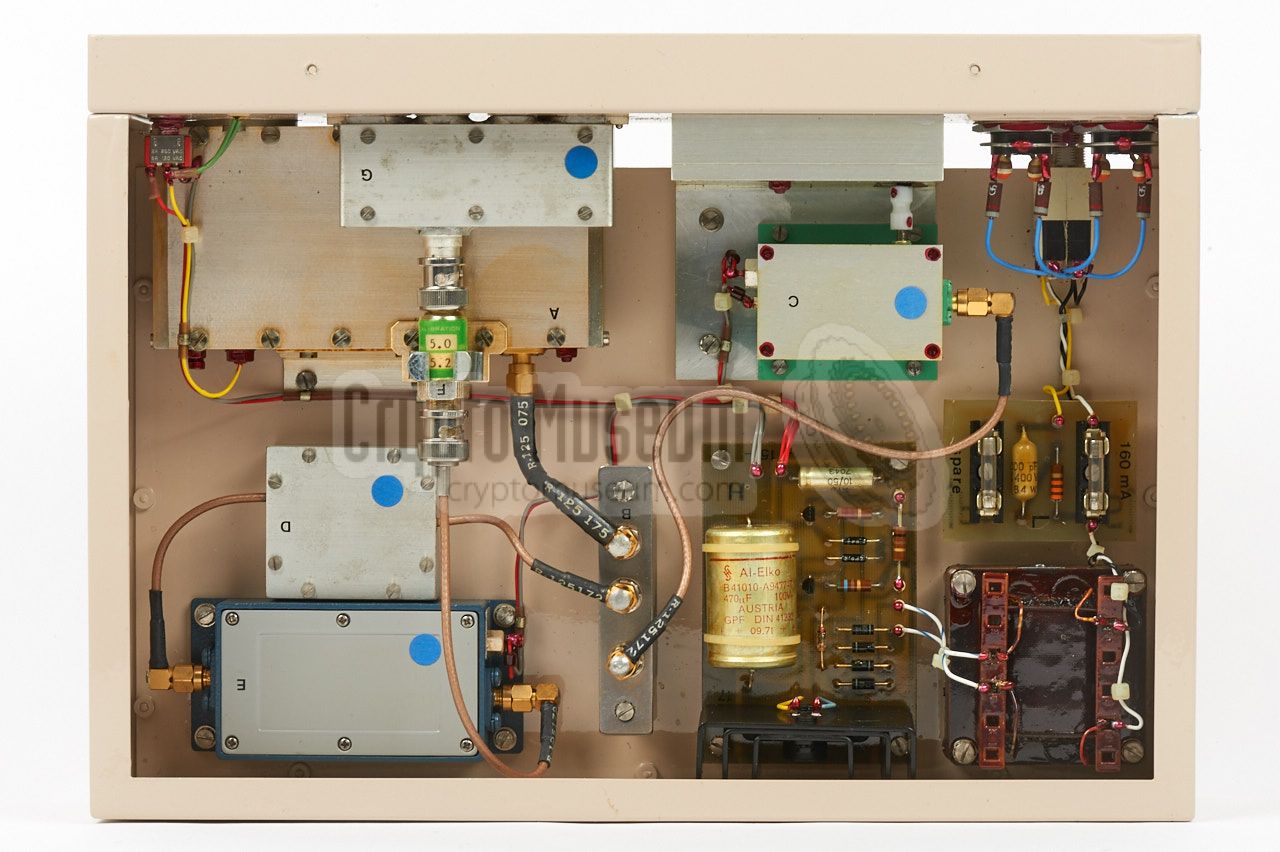
The interior can be accessed by removing four screws around the edges
of the front panel (two at the top and two at the bottom) plus one
large bolt at the rear.
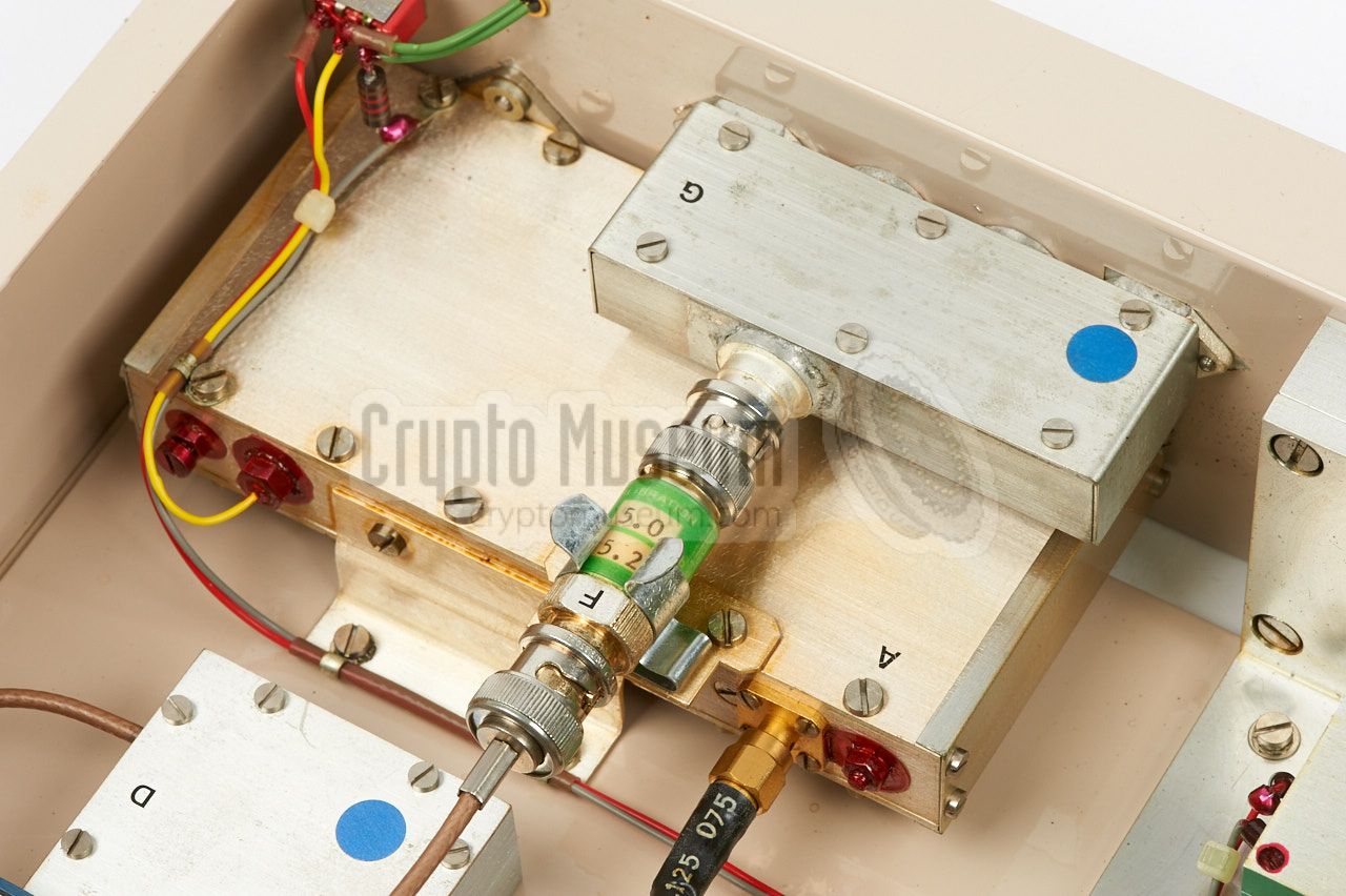
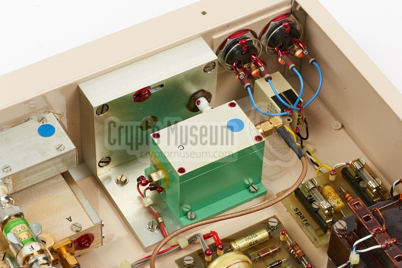
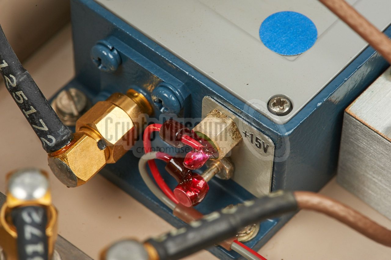
After sliding-off the case shell, the well-organised interior
is exposed, as shown in the image above. The internal construction
is very neat and robust, and the individual parts are easily
recognised by following the block diagram above. Some of the parts,
such as the mixer and the pre-amplifier
were readily bought from other manufacturers, but some of the
critical parts, such as the input filter,
were purpose-built at the NRP.
|
- Manual for Prototype Band 5 Conversion Equipment
NRP, July 1971. CM302474.
- Manual for SRK-145 and SRN-58
NRP, June 1972. CM302479.
- Technical Manual for SRR-145
NRP, February 1973. CM302475/A.
- Abbreviated Operating Instructions and Technical Data on Modified SRR-145
NRP, February 1984. CM302475/B.
- Operating Instructions for SRR-145-B down-convertor
NRP, May 1984. CM302475/C.
|
- NRP/CIA, Collection of documents related to SRR-145
Crypto Museum Archive, CM302475 (see above).
|
|
|
|
Any links shown in red are currently unavailable.
If you like the information on this website, why not make a donation?
© Crypto Museum. Created: Thursday 09 March 2017. Last changed: Wednesday, 05 November 2025 - 11:39 CET.
|
 |

|
|
|