|
|
|
|
|

|
|
← Easy Chair CIA NRP Antennas
Directional 1500 MHz listening post antenna
SRN-55 was a compact wide-band directional Super High Frequency (SHF)
antenna, developed around 1970 by the
Dutch Radar Laboratory (NRP)
for the US
Central Intelligence Agency (CIA),
as part of a long-term research project under the name
Easy Chair.
The antenna covers a frequency range of 1300 to 1950 MHz,
and was commonly used as part of a covert Listening Post (LP).
|
The antenna consists of two square printed circuit boards (PCBs),
each of which contains a feedline with several pseudo-conical elements,
that together form a phased array antenna which covers the full 1300-1950 MHz
frequency range, whilst providing a excellent gain of ~ 17dB [1].
The SRN-55 antenna was typically used as part of a listening post (LP) for
the reception of a covert listening device (bug) operating between 1300
and 1600 MHz, such as the
SRT-107.
In that case, the SRR-145 downconverter
and an SRR-56
or SRR-91A receiver were also needed.
|
|
|
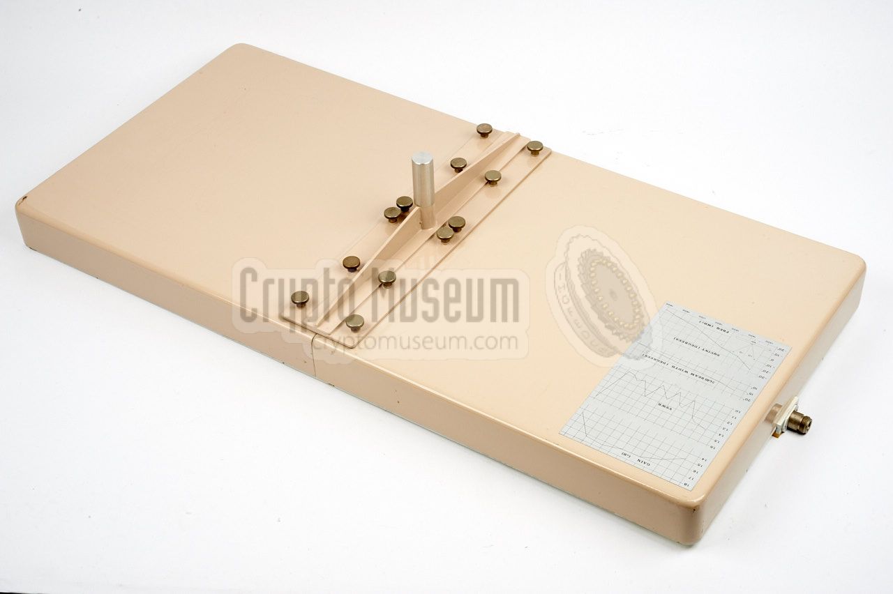
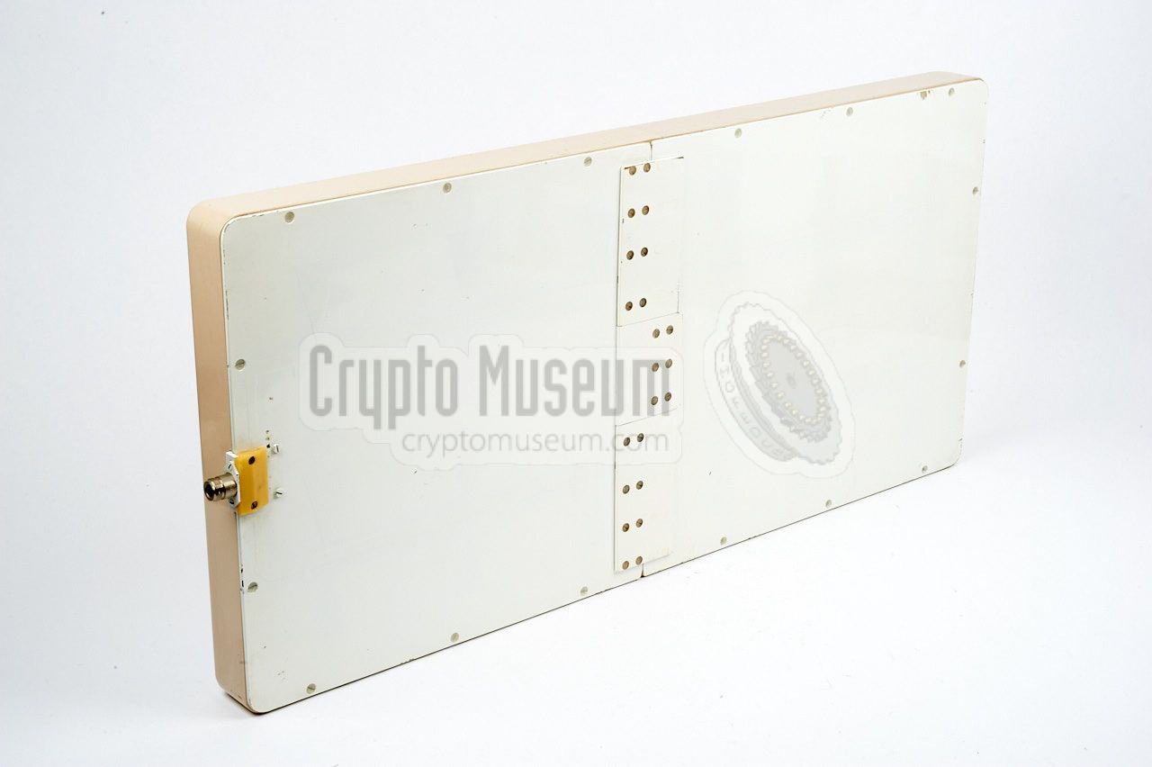
The image above shows a typical SRN-55 directional antenna, as seen from the rear.
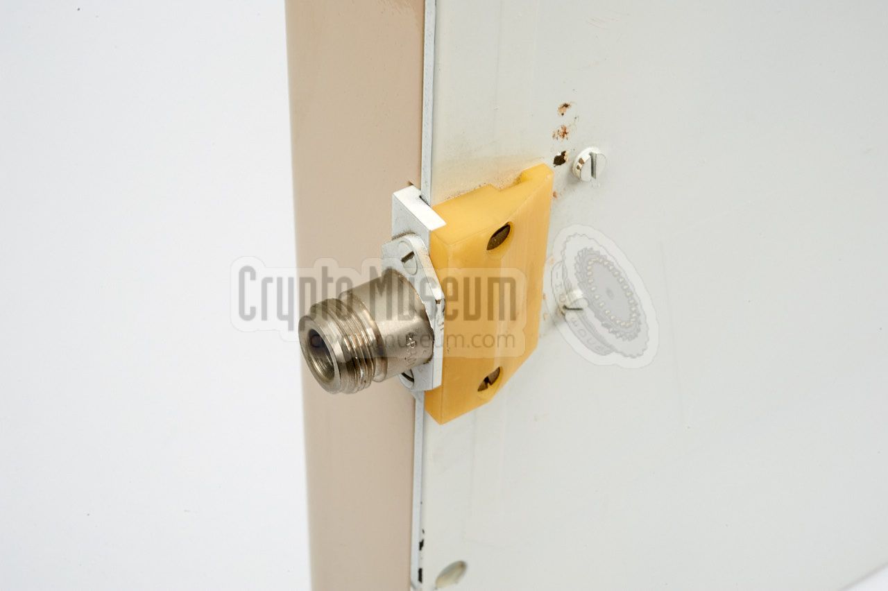
It is housed in a protective cream polyester enclosure, with an N-type
antenna socket at the feedpoint at the right.
The actual antenna PCBs are at the other side
(not visible here) and are painted white.
The metal frame
at the center provides extra strength
and enables tripod mounting. It was generally placed
horizontally to match the vertical polarization of the
SRN-58 antenna of the
transmitter.
|
The diagram below roughly shows the layout of the SRN-55 antenna.
As it is a collection of in-phase stacked dipoles, the direction of
radiation is at an angle of 90° from the surface, as shown by the arrow
marked Normal. The more dipoles are used, the narrower the beam width will
be.
The actual beam width is illustrated here by two purple planes and varies
between 10 and 17 degrees over the entire frequency range. The angle of the
entire beam (as seen from the Normal) also deviates with the frequency
between -25 and +15°. This angle is known as the Squint
[4].
|
The antenna has been optimised for the 1300 - 1950 MHz range, but its
characteristics are by no means constant over this range. The following four
diagrams are printed on a label at the rear side of the antenna, so that its
behaviour at a particular frequency can easily be predicted.
The gain is between 14 and 17.5dB over the entire range, with the best
performance between 1500 and 1800 MHz and a peak around 1700 MHz. The relatively
high gain is caused by the fact that the beam width is rather small as a
result of the stacked dipoles. Note that the antenna is used on its side,
in order to obtain vertical polarization, which is done to match the
transmitter.
The Voltage Standing Wave Radio (VSWR) is a measure for the impedance
mismatch between the antenna and the transmission line [2].
A value of 1.0 indicates an optimum impedance match in which
no power is lost. A VSWR below 1.5 would be acceptible for
the given frequency range. The diagram above shows
the measured VSWR of the SRN-55 over its entire frequency range,
which is never worse than 1:1.6.
The best performance is obtained between 1400 and 1850 MHz.
The width of the beam decreases nearly linearly when the frequency increases.
It practice it will be between 10° and 17°, with the narrowest beam (10°)
occuring at 1900 MHz. The narrow beam is partially responsible for the
relatively high gain of this antenna over its entire frequency range.
The antenna is constructed from a number of stacked dipoles that are
interconnected by a fixed-length transmission line. This fixed-length line
can be seen as a non-variable phase shifter (φ).
Ideally, we want all dipoles
to be in-phase, but this will only occur on one particular frequency (1500
MHz in this case). At other frequencies, the (unwanted) phase shift) produces
a virtual tilt of the beam, which is known as the Squint [4].
As the SRN-55 is commonly placed horizontally
(as illustrated in the diagram at the top of the page),
the Squint adds a virtual rotation to the beam.
|
|
|
|
Any links shown in red are currently unavailable.
If you like the information on this website, why not make a donation?
© Crypto Museum. Last changed: Saturday, 06 October 2018 - 15:05 CET.
|
 |

|
|
|