|
|
|
|
|

|
|
NRP CIA EC EC IV → ← EC II
The reason for adding subcarrier modulation (SC) was to improve the
system's secrecy. 1 With the earlier EC I
and EC II, the signal could
accidently be picked up by someone scanning the waves. 2
By adding SC to the concept, an eavesdropper would only hear a silent
carrier and not the actual audio. In the listening post (LP) the signal
had to be demodulated twice in order to retrieve the original audio.
Improved secrecy is also known as
audio masking,
and the EC III was one of the first attempts to implement this feature. 3
|
|
|
Development of the EC III started in May 1957 with several studies into
an increased operational range, an improved PE in a new enclosure, a
battery-aided variant, and improved sensitivity of the receiver [A].
The reported findings were largely influenced by experiences
gained when bugging the Russian Embassy in the Hague (Netherlands)
from December 1958 to June 1959, in a joint operation of the
CIA
and the Dutch BVD.
A prototype of the EC III was used in this operation [E].
The EC III was a great improvement over the earlier
EC I
and EC II systems, especially
with respect to the improved listening post and the fact that
the PE could now be used vertically. Nevertheless, it had some serious
shortcomings that were largely due to the properties of the early
transistors. Some of these problems were solved during its lifetime,
with updated versions in 1959 and 1960.
The EC III was succeeded in 1961 by the EC IV
and finally in 1962 by the fully redesigned EC V.
|
 |
-
The use of a Frequency Modulated (FM) subcarrier also makes the device
insensitive to obstructions in the signal path – such as a car passing by –
which would affect the Amplitude Modulated (AM) base signal.
-
TSCM equipment (bug tracers)
that were able to demodulate subcarrier
modulated transmitters, were not generally available until the mid-1970s.
One example is the
Scanlock Mark VB.
-
In 1958 it became apparent that the signal from the PE could
sometimes be demodulated accidently in a standard (non-SC) receiver.
This was caused by the fact that the subcarrier signal was nearly a
square wave that produced a multitude of harmonics.
This problem was fixed in the later EC V.
|
The diagram below shows the improved version of the Passive Element (PE),
known as EC Mark III PE, which was developed in 1958 for a CIA
bugging operation against the Russian Embassy in The Hague (Netherlands).
The slimline design was ideally suited for embedding inside a piece of
furniture and could easily be adjusted to the (dielectric) environment.
After the bugging operation it became a standard EC III component, that
was also available in a battery-aided variant.
The PE is in fact an open dipole, consisting of a tick and a thin element.
The thicker part contains the electronic circuit, whilst the length of the
thin part (the other half of the dipole) can be aligned in order to
match the environment (air, wood, concrete, etc.). The interior is not
accessible, as the entire electronic circuit is potted in black epoxy.
At the bottom end are two (or three) wires for connection of a microphone,
such as the Shure MC30. The three-wire PE variant is shown here.
|
|
EC Mk III introduces the following improvements over its predecessors:
|
The diagram below shows how the EC III system works. At the left is
the Listening Post (LP) in which all active components are housed in a
single enclosure, known as the transmitter cabinet. The LP features
an automatic duplexing unit that allows transmitter and receiver to be connected to the same antenna. It also eliminates the dependency on the
phase of the reflected signal.
At the right is the Target Area (TA) where a Passive Element (PE) is
concealed. The PE is powered by the strong RF signal beamed at it from the
LP.
Any sound that is picked up by the miniature microphone, is amplified by a
3-stage transistor amplifier. To make the bug more difficult to detect, the
audio signal is
masked
by modulating it onto a 100kHz
subcarrier
using Frequency Modulation (FM). At the LP, the signal is demodulated twice
to reproduce the original audio.
|
Development of the EC III started in 1957, shortly after the introduction of the
EC II, at the request of the CIA. It was the intention to
enhance the operational range by approx. 50 metres and to redesign the
enclosure of the PE, so that it could be fitted more easily into a concealment.
It had also been concluded from earlier experiments, that it was better to
place the PE vertically, as it would make the system less sensitive to
the orientation of the concealment (e.g. a table leg).
The research on EC III was completed in January 1958 [C], after which the
first prototypes were built and the system was further improved. It was the
intention to have the final product ready by the end of 1958. By September 1958
however, the CIA had identified the
Russian Embassy in The Hague (Netherlands)
as a target and wanted the new and more secure EC III PE to be planted there.
Although this event delayed the official introduction of the EC III system
somewhat, the fact that NRP engineers were involved in the actual bugging
operation produced so much useful feedback, that it improved the overall
specifications and performance of the system. In fact, the feedback was even
used to the benefit of the later EC IV
and in particular the
Easy Chair Mark V project.
|
|
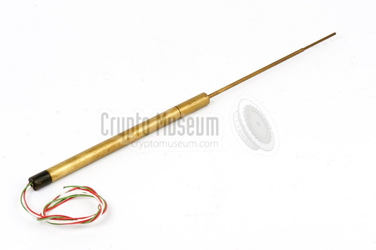
The actual transmitter (bug) of the EC III system is a so-called
Passive Element (PE) that does not need a local power source, such as
a battery. Instead it is powered by a strong RF signal beamed at it
from the Listening Post (LP). The PE of the EC III is based on the
design of the earlier EC I.
|
The PE is actually an open dipole with a length of approx. ½λ.
The dipole consists of a tick and a thin half that are screwed together
at the center. Contrary to the PE of the EC I,
this version does not
need an external amplifier, as its electronics are embedded inside
the dipole's thick half.
For this reason, the antenna can also be seen as an end-fed
skirt antenna or sleeve antenna. All parts of the PE,
with the exception of the microphone, are embedded inside the antenna
itself. Three teflon wires (white, red and green) extend from the potted
bottom end of the thick half.
|
|
|
These wires are for connection of the low or high impedance microphone
that should pick up the sound in the bugged room. As the microphone is
no longer connected at the feedpoint, like with the
EC I
and EC II,
the antenna may now be installed vertically, making the bug
omni-directional.
|
Another improvement of the new design is the fact that audio is now
Frequency Modulated (FM) onto a subcarrier signal.
This is done by adding an extra transistor to the new circuit diagram.
The CS2A detector diode, or crystal as it was called at the time,
is now located at the feedpoint-end of the thick rod. It is very
sensitive to strong RF fields and may be damaged when the
PE is tested in close proximity of the exciter.
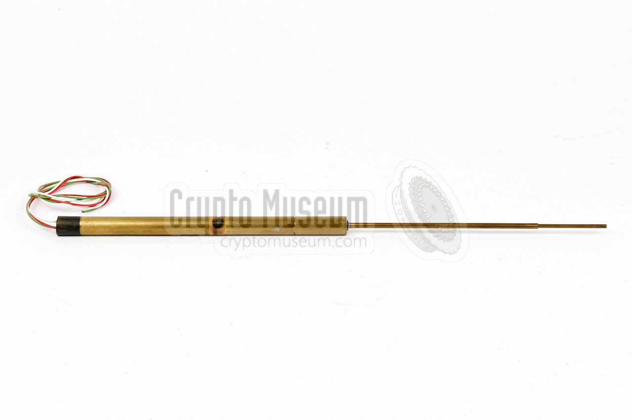
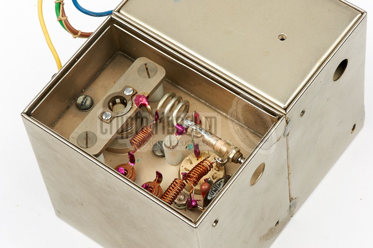
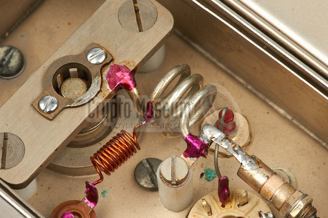
The image on the right shows the thick half of the PE with the
actual electronic circuit to its left.
The detector diode (crystal) is at the front.
|
|
|
The threaded cylinder (inside the perspex insulator tube) can be
unscrewed with a special tool, after which the detector diode can
be removed. In the image above, the cylinder of the rear unit
has been loosened. In some versions the cylinder was fixed
in place by a thin metal pin.
It is believed that this type of PE was used for
bugging the Russian Embassy
in The Hague in 1958.
|
Althoug the PE is suitable for connection of virtually any type of high
impedance dynamic microphone, or in case of the 3-wire version even a
low-impedance one, it was commonly used in combination with a small Shure
MC-30 hearing-aid part of approx. 12.5 x 12.5 x 6.5 mm that had just
become available in 1958 [2].
The Shure MC-30 was later succeeded by the MC-30J, which is also known by
its National Stock Number NSN 5965-00-015-7408.
➤ More information
|
|
|
Another microphone that was used with the EC III and later models,
was the so-called Type-B shown in the image on the right.
It is based on the RCA BK-6B studio microphone, but is housed in
a special CIA-provided enclosure that allows it to be used as a
covert probe microphone.
Although this microphone is much larger that the Shure MC-30
shown above, it is more sensitive, has a better frequency response
curve and has a better dynamic range.
➤ More information
|
|
|
The block diagram below shows how the PE of the EC III works. The antenna
and the detector diode are identical to those of the
EC I
and EC II.
The difference was however, that the entire circuit was built inside one
half of the dipole antenna, allowing it to be placed vertically.
The actual circuit is built around four transistor stages, as opposed
to three in the earlier design. Note the insertion of a subcarier oscillator
the frequency modulates (FM) the audio signal onto a subcarrier of approx.
100 kHz. Due to the use of a subcarrier, the bug is more difficult to detect.
|
|
|
Fully passive variant
EC Mark III
|
|
|
Like with the earlier designs, the circuit diagram is split in two parts:
the antenna/detector and the actual audio amplifier. The antenna consists
of two brass tubes of equal length, screwed together at the center by means
of an isolated section. The diode is housed inside the isolated section.
Like with the EC I and EC II, a CS2A diode (or crystal as it was
called) was used in the antenna circuit. From March 1959 onwards however,
the crystal was replaced by the 1N21C which had superior specifications,
and offered an additional 1.25 dB improvement of the link budget [D].
Below is the circuit diagram of the audio amplifier. The first two stages
are built around Philips OC71 transistors. They are the amplifiers for the microphone
signal. Note that this part of the circuit is simplified from the earlier
designs and that the bias resistors in the base circuit of the transistors
are missing. This was possible due to the internal leakage of the OC71,
but made the PE sensitive to temperature changes.
As a result, this PE doestn't work at temperatures over 30°C.
The rightmost two transistors are of the type OC44 and form a feedback
oscillator that produces a square wave of approx. 100 kHz, onto which the
audio from the first two stages is frequency modulated (FM). The exact
subcarrier frequency depends on a number of factors, such as the R/C
combination in the feedback loop and the internal resistance of the last
two transistors, which is partly voltage dependent. As a result, the
100 kHz subcarrier was not very stable. It was improved in the later
EC Mark V design.
Transistor T4 amplitude modulates (AM) the antenna like before.
Sometime during the lifetime of the PE, the circuit was upgraded to
include an impedance transformer at the microphone input, allowing
the use of both high and low impedance microphones. Also added in this
variant is a 47p capacitor across the detector terminals, which was
probably added to reduce the harmonics of the subcarrier, and hence
improve secrecy.
|
|
|
Battery aided variant
EC Mark III-A
|
|
|
As an alternative to the above fully passive target element,
a battery aided variant was developed, in which a long-life
battery provides the energy for the low-current circuitry. As a result,
the circuit no longer has to rely on the voltage delivered by the
RF energy from the LP, resulting in a path gain of some 12 dB.
The disadvantage of this solution is that the bug will
have a limited life.
Lab tests had shown however that a mercury battery would last for at
least 6 months, making it ideal for short-term operations. As the PE
doesn't contain a transmitter, it will only produce a modulated signal
when it is hit by the activation beam from the LP. The 12 dB extra gain
was used to extend the operating range (i.e. the distance between the
LP and the TA) or to lower the power of the activation beam, which
reduced the chance of discovery. The mercury batteries were
sealed to prevent them from leaking through
the concealment after they had been exhausted.
|
|
At the listening post, all items are built inside a single cabinet. This
includes transmitter, receiver, duplexer and power supply unit (PSU). The
single unit is known as the transmitter cabinet, and can
be transported in a travel suitcase, along with part of the antennas.
A second suitcase contained the remaining parts of the antenna and the
various interconnection cables.
|
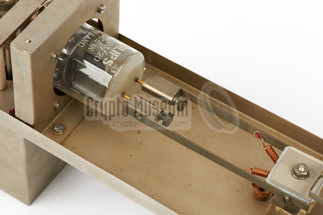
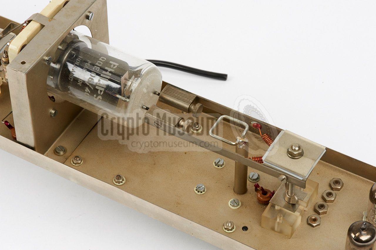
The transmitter is completely built with valves (tubes).
It consists of a free-running oscillator that is tuned to
the target frequency of approx. 378.5 MHz, just like with the
EC I system.
The crystal oscillator and the various multipliers of the
Carrier Pigeon system (EC II)
have been dropped. The signal from the oscillator is fed to
a pre-amplifier, built around a QQE 03/20, and is finally amplified to the
desired output level (adjustable between 0.4 and 40 W)
in the QQE 06/40 valve.
A small portion of the energy from the oscillator (~100 mW)
is extracted by means of a pickup loop, and fed directly to the
Local Oscillator (LO) input of the receiver, where it is mixed
with the incoming signal from the Passive Element (PE).
At the top right is a detector/feedback circuit that controls
the output power in the range 0.4-40 W.
It is also driven by a measurement circuit in the duplexer,
allowing the output power to be reduced automatically in case of
an antenna mismatch.
|
The transmitter shown above is one of the few surviving parts of
an Easy Chair Mark III listening post (LP). It suffers from minor
corrosion, but given its age (1958), it is in extremely good condition.
Although its wires have been cut-off, it could probably be made operational again.
|
The receiver is a hybrid of valve and transistor technology.
The first two stages - amplifier/mixer and AM diode detector -
are built with valves, as they are more tolerant to excessive signals.
The remainder of the receiver (i.e. the IF and AF stages) are built
with silicon transistors. Furthermore, there are two identical input
stages, each of which gets its signal from the duplexer, albeit with
a phase difference of 90°. This eliminated the effects of
the spillover phase (phase-indifference).
In the above block diagram the valve-based parts are marked in grey.
The other blocks are all transistor-based. After shifting the phase
by 90° in the upper channel after the detection stage, the two signals
are added together and filtered in an adjustable subcarrier (SC) filter.
After further amplification, it is then fed to an FM discriminator,
after which the resulting audio is amplified to headphones level. A
squelch circuit mutes the audio when no usable subcarrier signal is present.
|
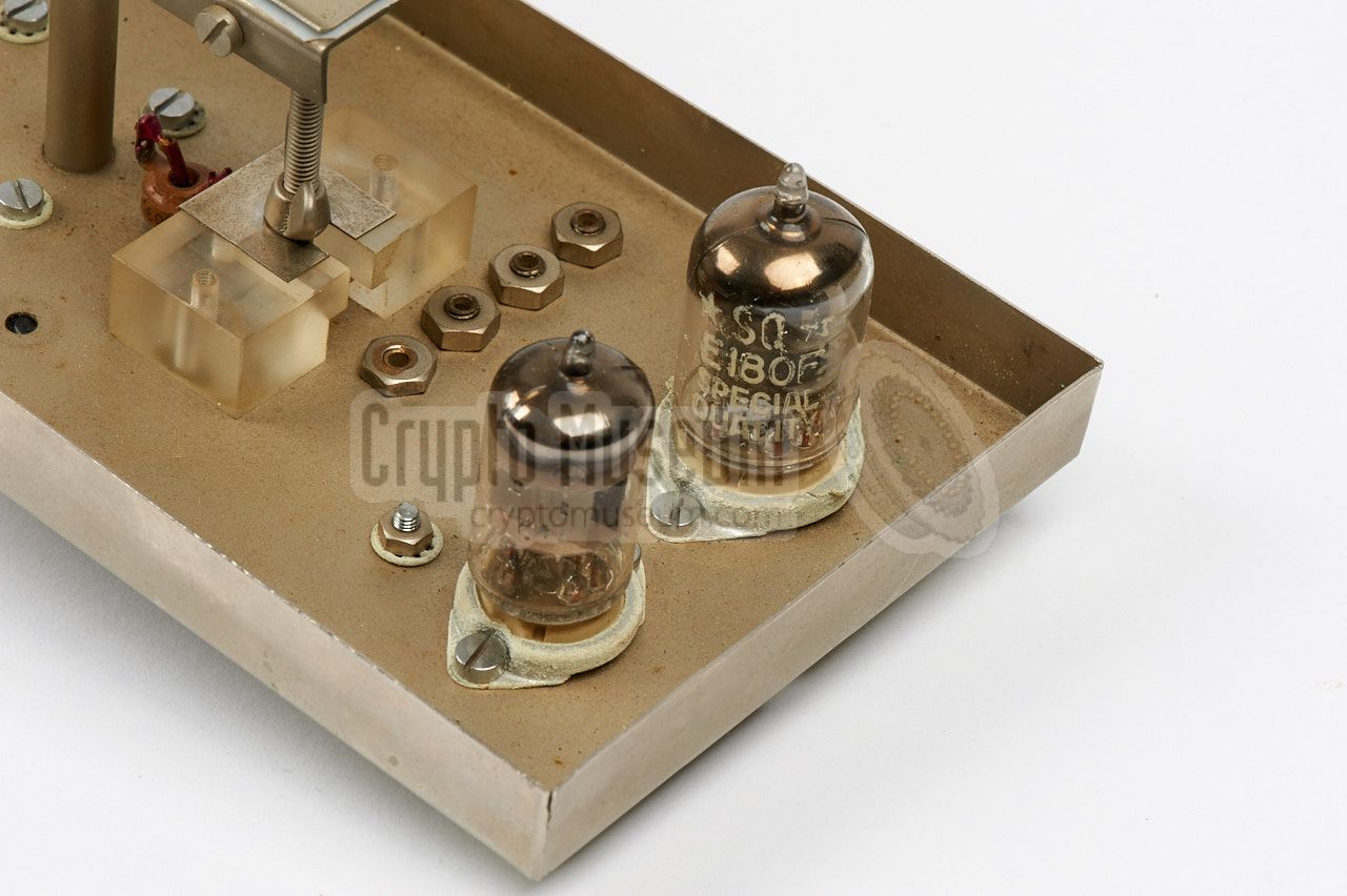
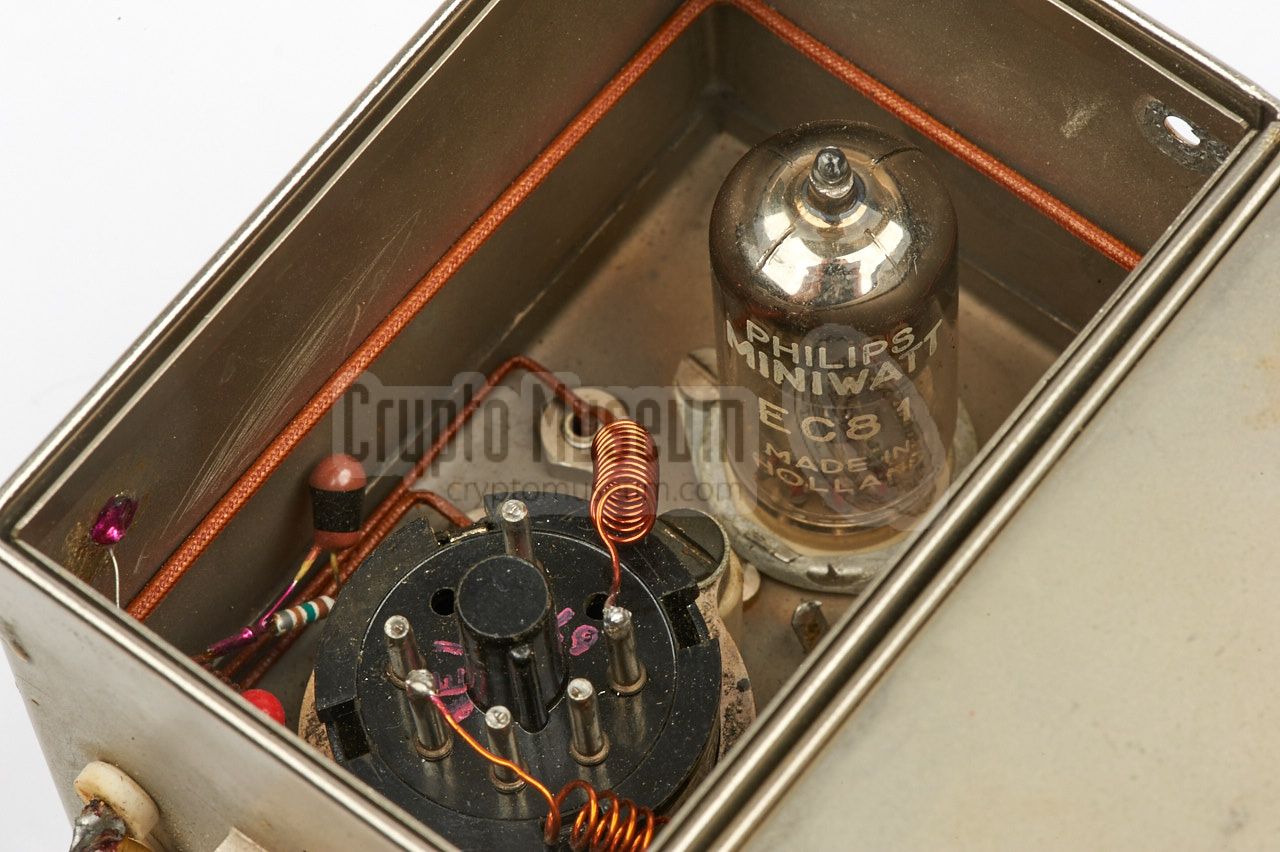
The image on the right shows a close-up of the receiver's valve-based
front-end, which is the part that is coloured blue in the above diagram.
The first stage is built around a lighthouse type Philips EC56
in grounded-grid configuration. At the input, the local oscillator
signal, derived from the transmitter's master oscillator, is added to the
RF signal. The second stage is built around an EC81 valve that
acts as an AM detector. It recovers the Frequency Modulated (FM)
subcarrier which contains the audio from the PE, that
is demodulated in the following IF stages.
|
|
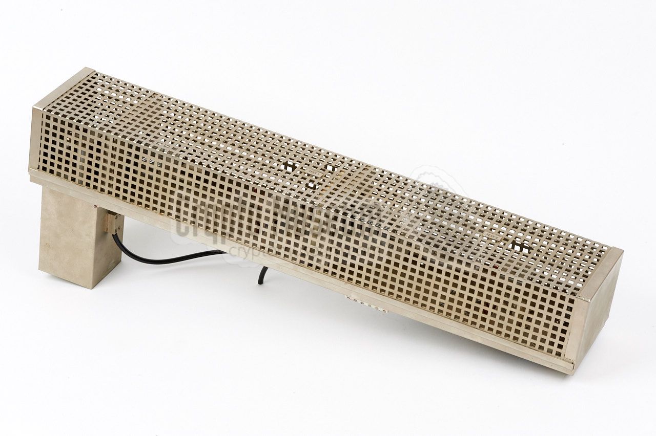
|
The RF front-end is housed in a heavily shielded silver-plated metal
enclosure of which the top and bottom panels can be removed. The valves
are accessible from the top, whilst the contacts of the EC81 are available
at the bottom. There are two front-ends (one for each path) that are mounted
side by side. The inputs, outputs and power terminals, are all available
at one side.
|
The most special part of the EC III Listening Post (LP) is the
duplexer,
which seperates outgoing and incoming radio signals on the same
frequency. The duplexer in fully made in stripline technology and was
purpose-built for the EC III. The diagram below shows roughly how it works.
At the bottom left is a 10 dB directional coupler. The output of the
transmitter is connected at the bottom left of the red line, whilst the
antenna is connected at the end of that line, at the top left.
The reflected signal from the Passive Element (PE), is available from
the green arm of the 10 dB directional coupler, at the bottom right.
Two receiver outputs are created here, one of which has a phase shift
of 90° (i.e. a delay of 1/4λ). This extra output is used in the
receiver to cancel out the effects of the phase error between
transmitted and refected signal. As a result, the operator no longer had
to move the antenna array back and forth as part of the setup procedure.
|
At the top right is an extra 30dB coupler (purple) that is used for
measuring the amount of energy returned by the antenna. In case of a
mismatch, this reflected energy may potentially be harmful to the
transmitter and the receiver. A measuring circuit fitted to the output port
of the purple arm produces a signal
that reduces the output power
of the transmitter automatically when necessary.
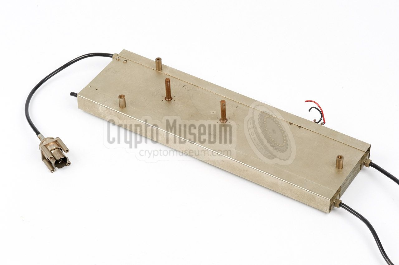
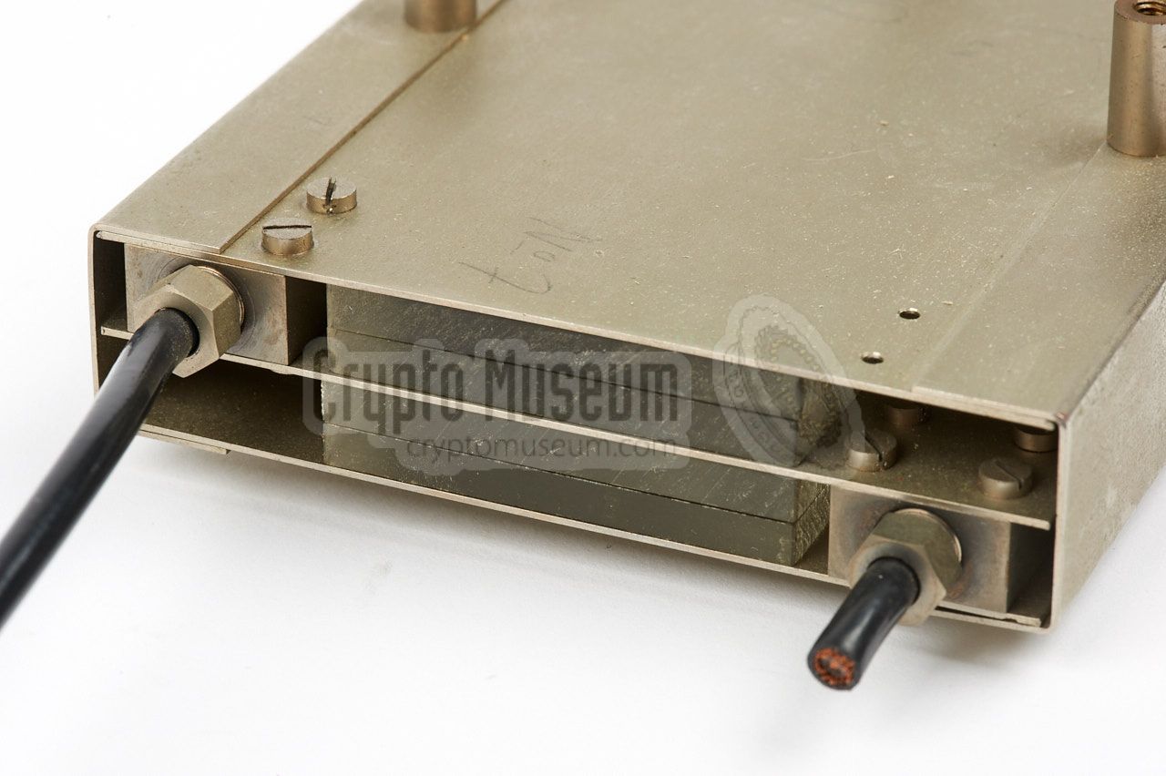
The image on the right shows the
original Easy Chair Mark III duplexer,
which has two decks: a front deck that contains the red and purple
arms, and a rear deck that holds the green RX arms.
|
|
|
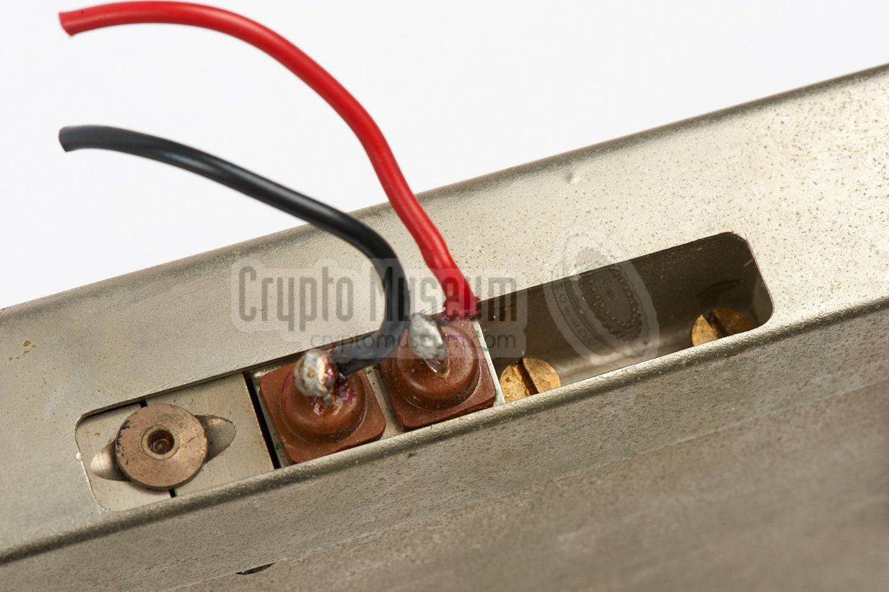
Note that part of the red arm is also on the rear deck. In the image above,
the connections for antenna (left) and transmitter (right) are clearly visible.
At the other side
are the two connections for the receiver. Although the cables
are cut, it should be possible to make it operational again.
|
|
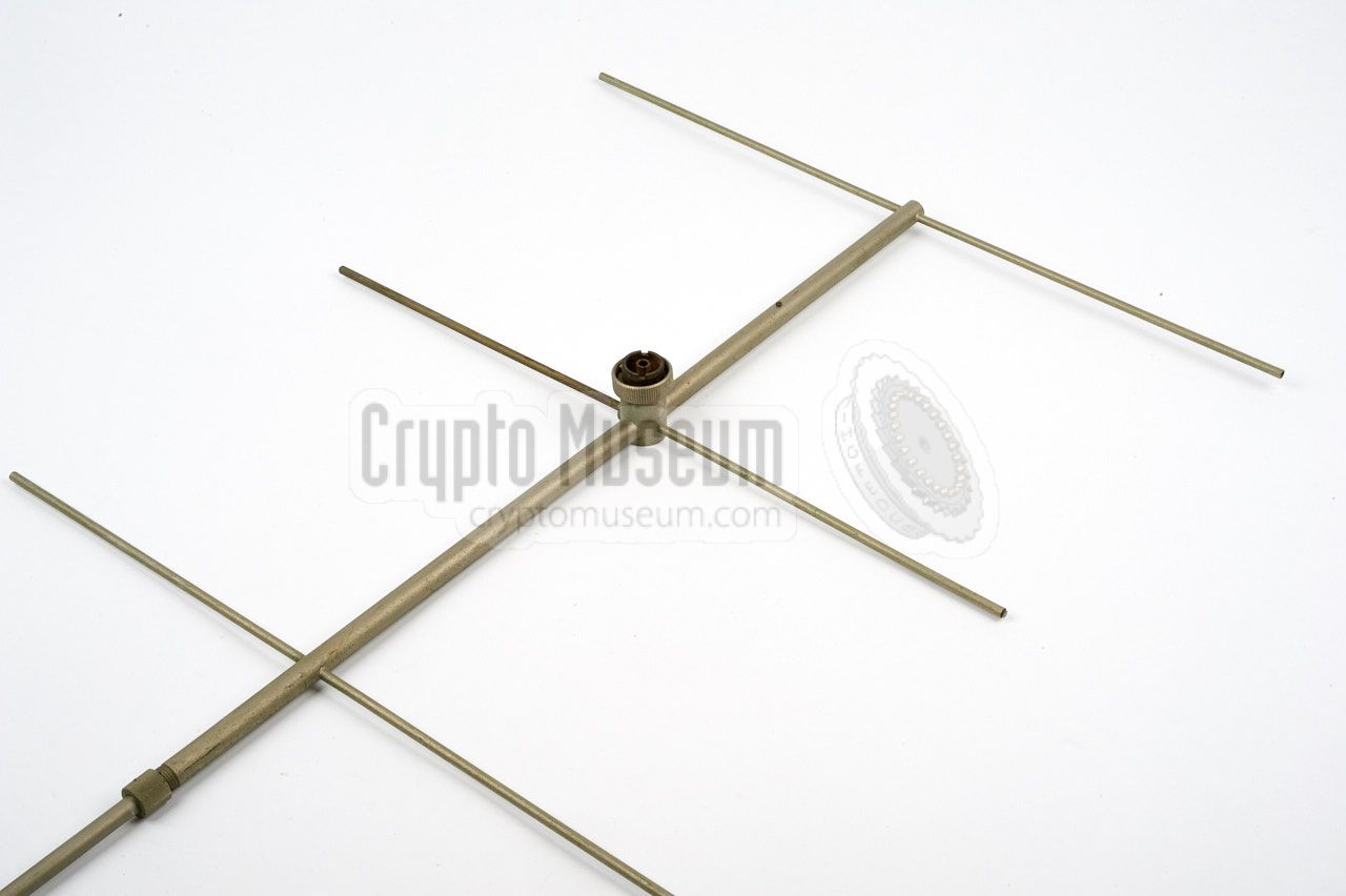
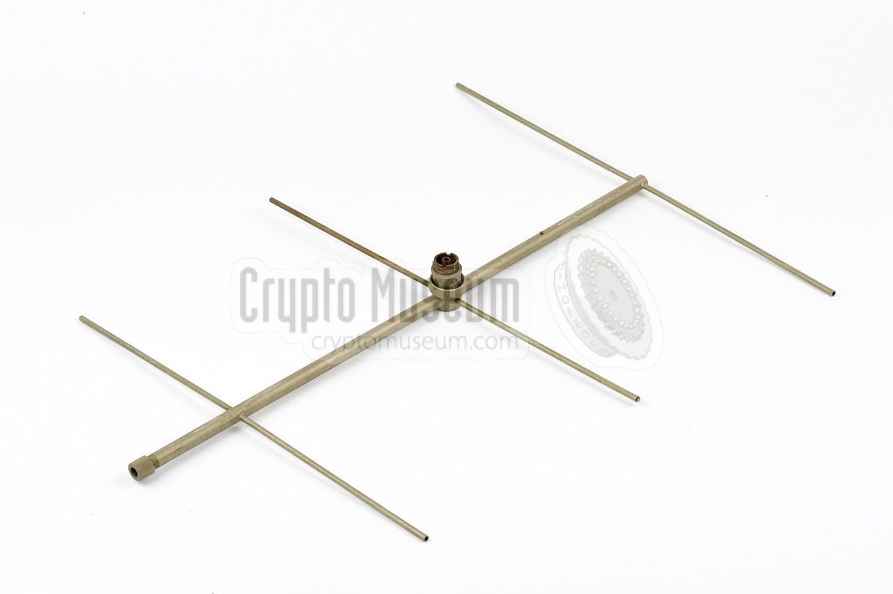
Like the EC II system, the EC III was used with an array of Yagi antennas,
but instead of just two, the EC III had four of them, offering a gain of
17 dB. The antennas were
connected in a broadside arrangement, using so-called Magic-T coupling
arms. Each array measured about 1 x 1 x 1 metre, which means that the total
space needed by a four-bay setup was approx. 2 x 2 x 1 metre.
|
Depending on the distance and the available space at the LP, the system
could be used with four or two arrays. If limited space was available it
could even be used with a single array.
The image on the right shows a single 6-element Yagi antenna that was used
in the experiments when bugging the Russian Embassy in The Hague (see
below). Each Yagi antenna consisted of two halves, so that it could be
taken apart and stored inside a common unobtrusive suitcase.
|
|
|
|
|
Bugging the Russian Embassy
|
|
|
|
In late 1958, in a joint operation of the
American CIA and the Dutch BVD,
an EC III PE was planted in The Hague,
in the office of the Russian Ambassador to the Netherlands.
NRP engineers and developers were involved in the operation
as they had to produce solutions for various problems that emerged.
The experiences gained from this operation were used in the final
EC III design [E].
|
It had become known to the BVD that the Russian Embassy had ordered
new furniture for the ambassador's office, and the plan arose to
plant a bug in one of the items. After consulting the CIA, it was
decided to conceal an EC III device – at the time under development –
into a desk.
Although the bug initially didn't work, mainly due to the large
distance between the embassy and the LP, NRP engineers eventually
managed to solve the issues and improve the overall system.
➤ Read the fully story
|
|
|
| Type | Mat. | Pol. | Pt | Vcb | Vce | Vcb | Ic | Tj | ft | Cc | hFE | Case |
| OC71 | Ge | PNP | 25mW | 20V | 20V | 10V | 10mA | 75° | 0.3MHz | 30pF | 30 | TO-1 |
| OC44 | Ge | PNP | 83mW | 15V | 12V | 12V | 10mA | 80° | 8MHz | 12pF | 100 | TO-1 |
|
|
| |
OC71/OC44 pinout - bottom view
|
|
|
|
|
Any links shown in red are currently unavailable.
If you like the information on this website, why not make a donation?
© Crypto Museum. Created: Friday 10 March 2017. Last changed: Tuesday, 06 June 2023 - 13:54 CET.
|
|

|
|
|
|