|
|
|
|
|

|
|
NRP CIA EC EC III → ← EC I
In addition, EC II also introduces a duplexer that allows
transmitter and
receiver to be connected to the same
antenna.
At the same time a 2-bay 4-element Yagi antenna is introduced,
which offers a gain of 15 dB. This partly compensates for the coupling
loss caused by the duplexer.
The reason for adding two-way communication is currently unknown, but it
was probably done to allow the operative who was covertly installing the
Passive Element (PE), to receive instructions from the Listening Post
(LP), allowing him to test the PE and find the best possible position
for it.
|
|
|
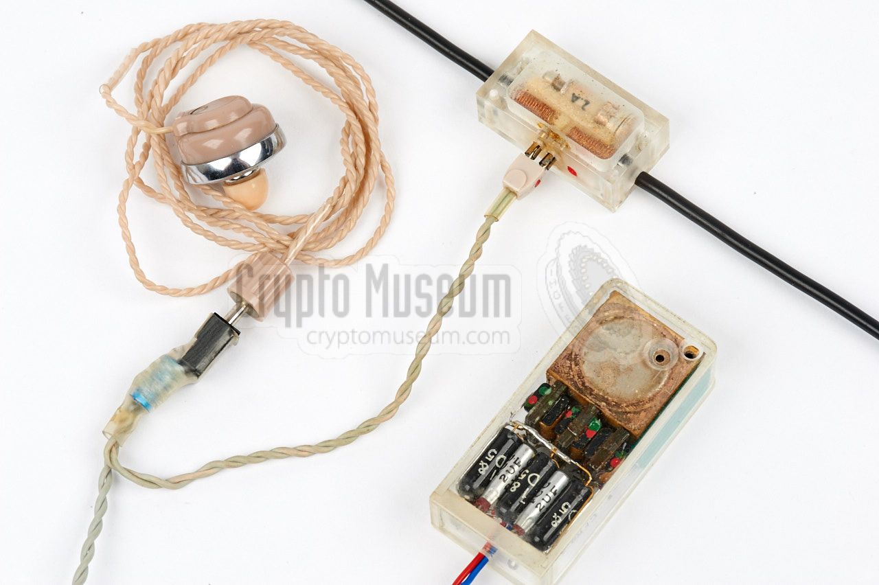
Adding two-way communication required quite a bit of additional circuitry,
both in the activation transmitter (actuator) and in the receiver at the LP.
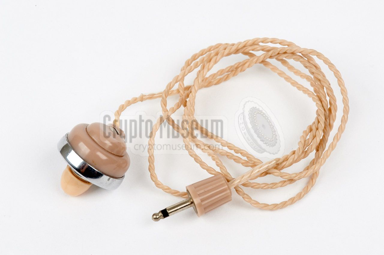
At the target area (TA), the operative only had to connect a pair of
headphones in parallel to the terminals of the crystal detector.
This way, the operative received instructions from the LP, but he could
also hear himself, which indicated that the PE was powered properly.
Once the PE was installed, the headphones were removed again.
Two-way communication was developed for the CIA under a separate research
contract with the name CARRIER PIGEON (CP).
It is likely that it was intended for one, or perhaps a few, specific CIA
operations, as it's features are not found on any of the later systems.
In 1958, the EC Mk II was succeeded by the much improved
Easy Chair Mark III (EC III), which had a fully redesigned
PE.
|
|
The EC II features the following improvements over the EC I:
|
- Duplex unit (single antenna)
- Redesigned activation transmitter
- Two-way communication
- Audio muting (pilot tone)
|
The diagram below shows how an EC II installation works.
At the left is the listening post which consists of an activation
transmitter (the so-called actuator), a receiver, a duplexing unit
and a suitable antenna array. As the EC II system is suitable for
two-way communication, a microphone with additional circuitry is added
to the transmitter, and a muting switch is added to the receiver.
At the Target Area (TA), a Passive Element (PE) is installed. The PE
is identical to the one used with the EC I system,
with the only addition that a pair of headphones could be connected
in parallel to the line between the detector (antenna/crystal) and
the amplifier. It allowed the operative to receive instructions from
the LP during installation of the PE. Once installation had been
completed, the headphones were removed and the PE
could be used as in the EC I system.
|
|
The Passive Element (PE) used at the target area
of an EC II installation, is identical to the PE of the
earlier EC I system. The circuit diagram is
unchanged, but only the Model B production variant was available.
This was the one that is housed inside a perspex enclosure, as shown below.
|
It came with a
three-stage transistor amplifier
that was housed in a separate perspex case, optionally with a
Fortiphone FM5 microphone
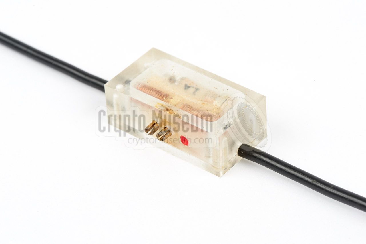
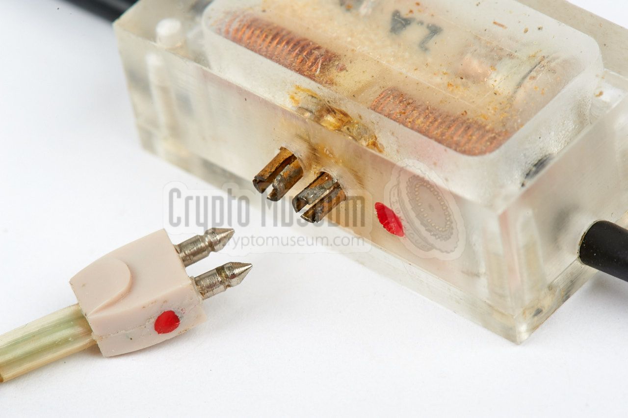
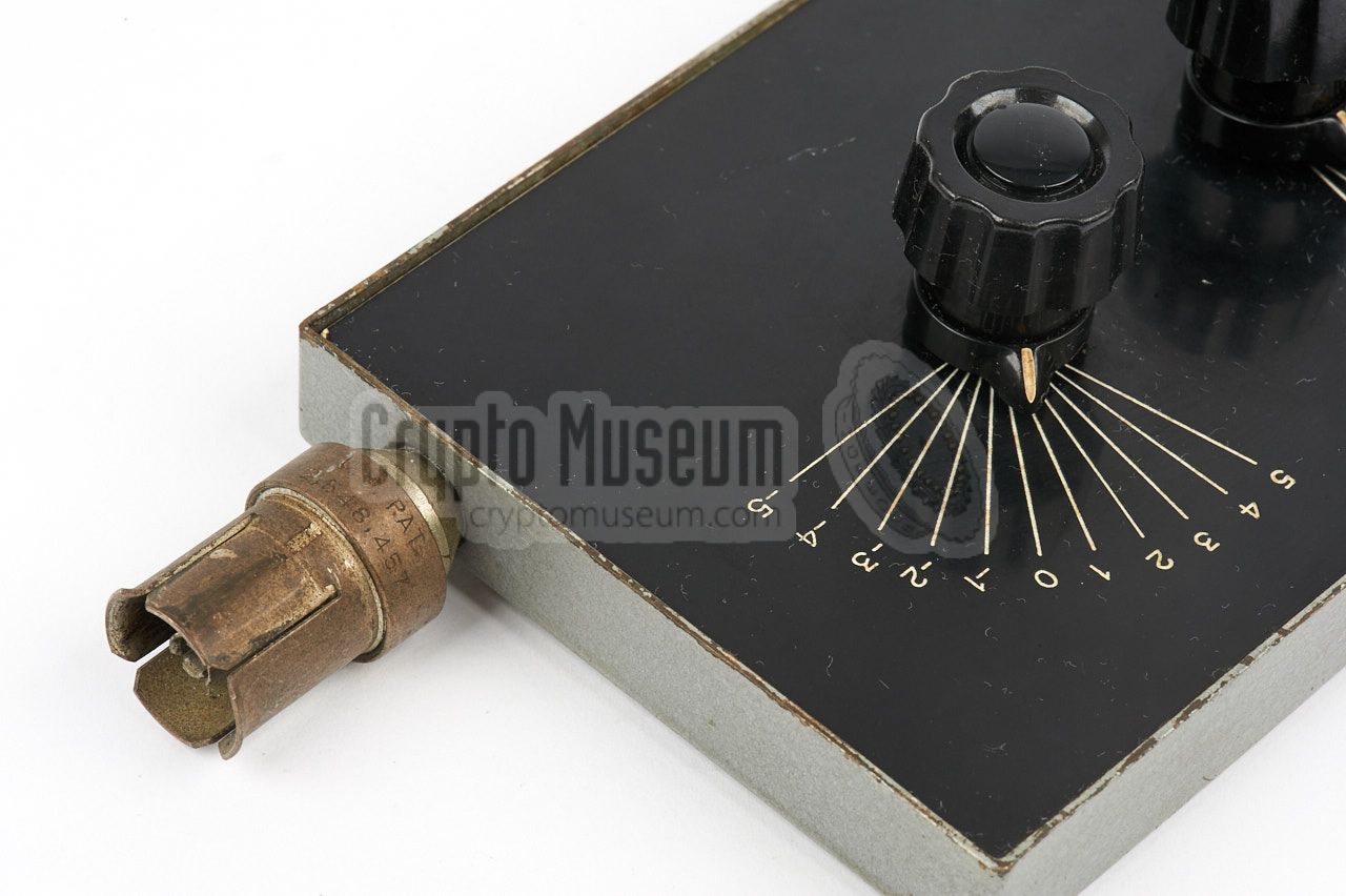
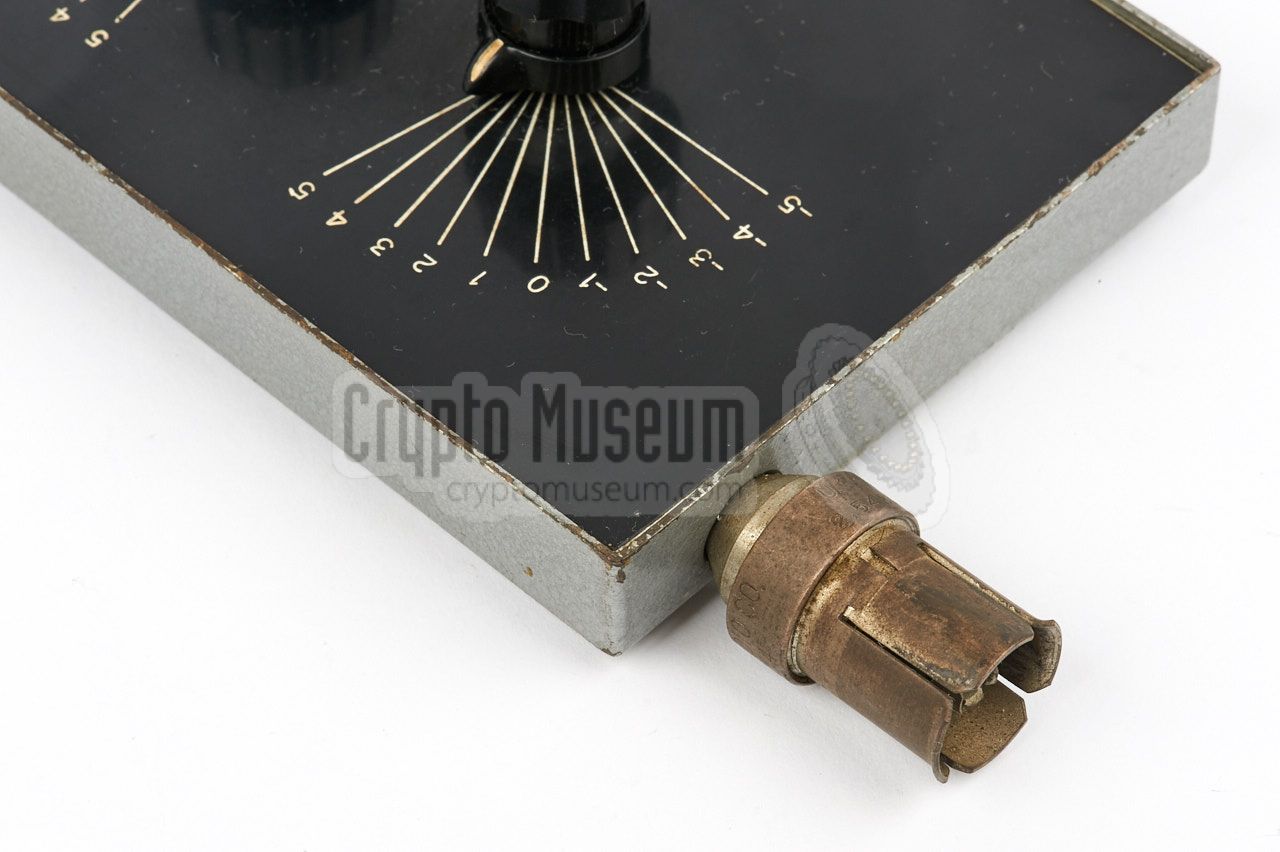
fitted inside. Unlike the EC I however, the EC II detector
did not have regular screw terminals.
Instead the terminals were a receptacle for a standard
TELEX miniature plug
of the era, such as the ones that were used on hearing aids. The image on the
right shows an EC II detector with a TELEX plug fitted. Note the presence of
a red dot on the plug, which has to be aligned with the red dot on the detector
case for proper operation.
|
|
|
|
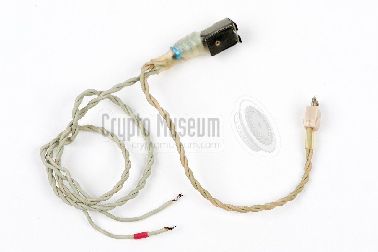
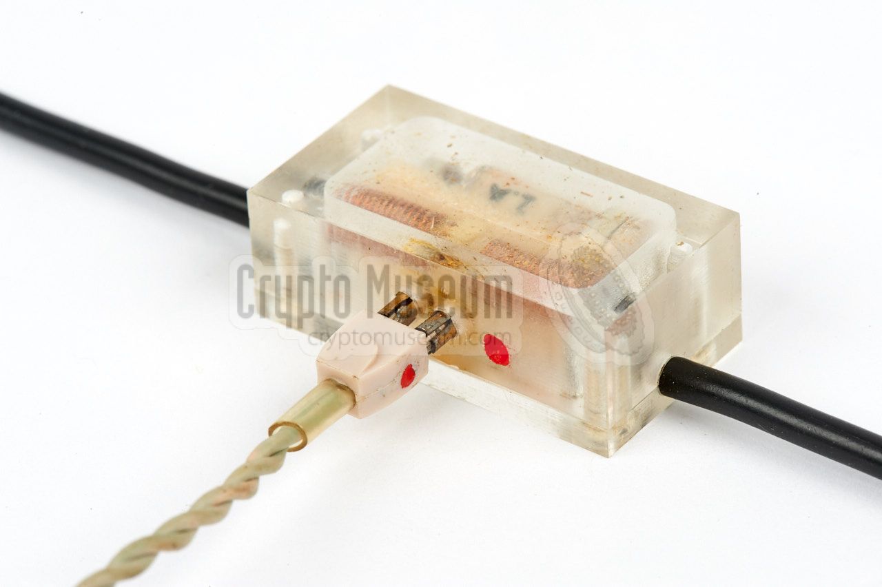
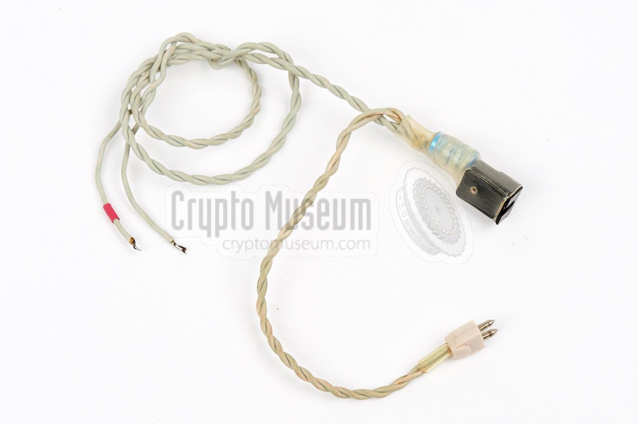
The reason for changing the terminals, is the fact that in the EC II system
it was possible to connect a pair of high-impedance headphones in parallel to
the line that connects the detector to the amplifier. This was done by inserting
a T-adapter between the detector and the amplifier.
|
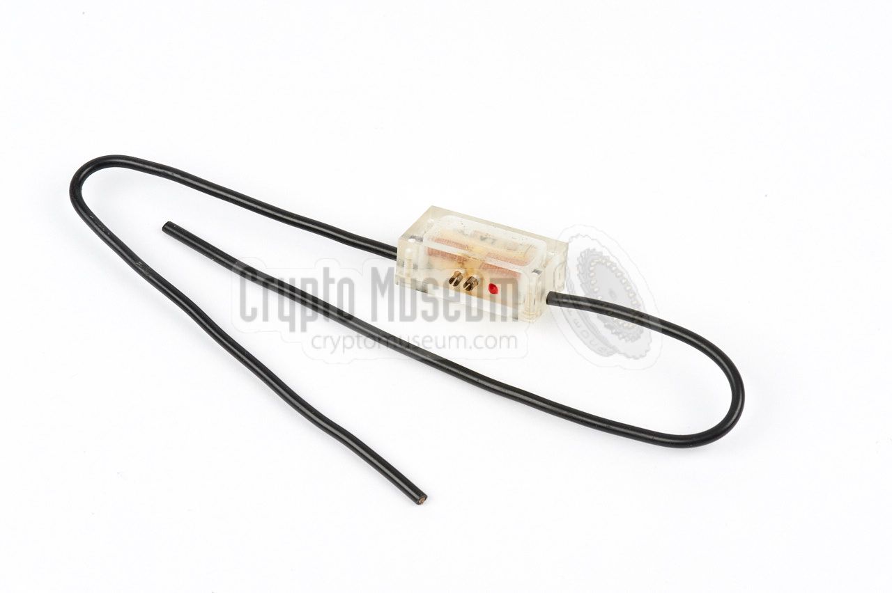
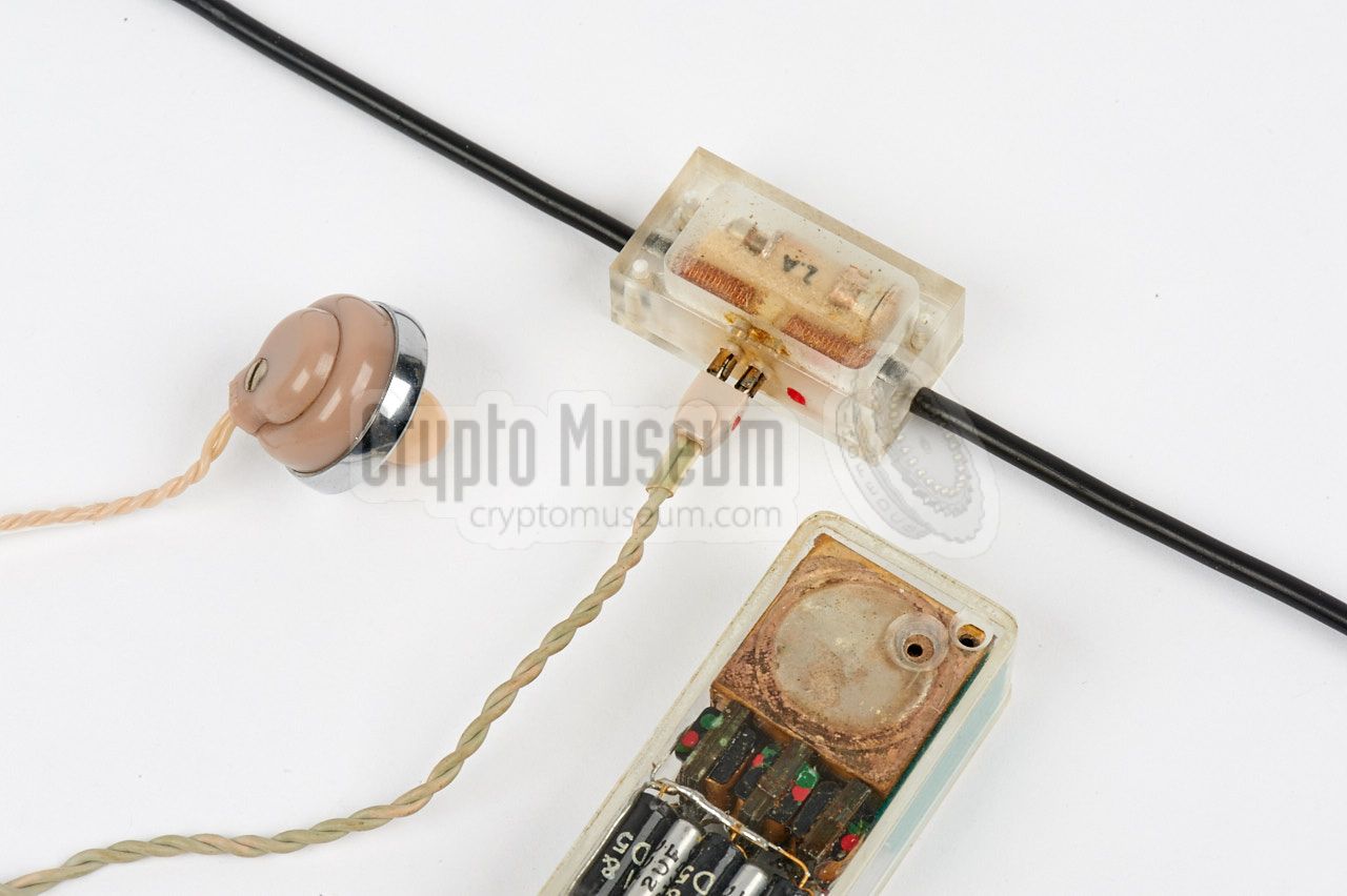
The T-adapter is also known as a Y-cable or a splitter cable.
Initially the adapter consisted of three twisted wire pairs, connected in
parallel, with TELEX plugs at the end. One of these plugs was later swapped
for a 2 mm jack socket, in order to allow the headphones to be removed more
easily once the PE setup was completed.
In the latter case, the T-adapter was commonly left in place after the
headphones were removed. The image on the right shows the later variant of
the T-adapter. It consists of a jack socket and 2 cables for connection
of detector and amplifier.
|
|
|
Note that a 1µF capacitor is mounted to the rear of the jack socket,
in order to block DC currents to the headphones.
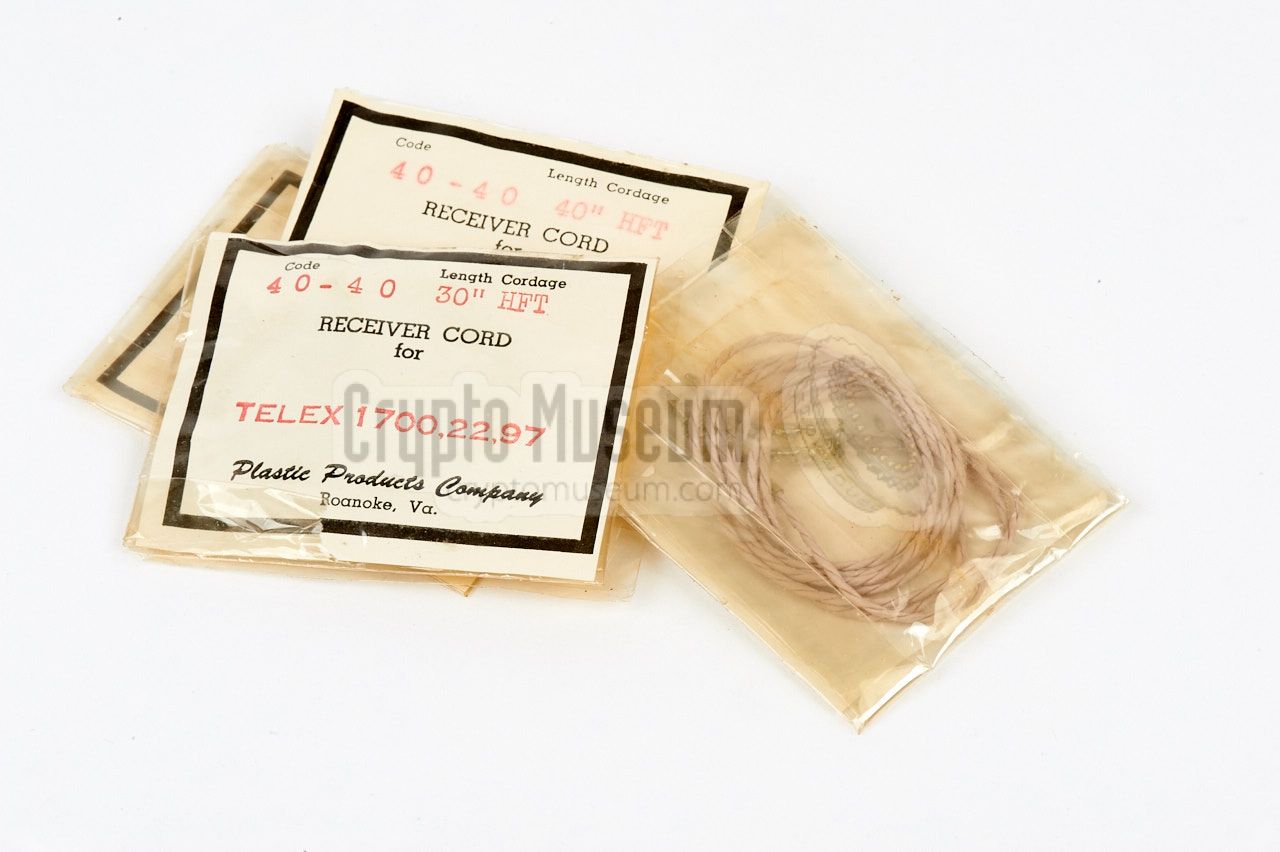
The twisted cables with TELEX plugs were usually ordered as spares
from companies like Telex, Fortiphone, Maico or Audium.
The sockets for these plugs were machined at the NRP, and
were constructed in such a way that they could also be used
as solder terminals.
For further details
about the PE, refer to the description of the
Easy Chair Mark I Passive Element.
➤ More information
|
The transmitter basically consists of two functional parts:
a rock solid valve-based transmitter, and a transistor-based speech modulator
with pilot tone generator.
The transmitter is crystal-driven and produces an adjustable output power
between 0.4 and 40 Watts at approx. 378 MHz.
The first stage is built around an E180F that is used as oscillator
and tripler. It is followed by two further triplers with QQE 03/12,
a QQE 03/20 driver stage and finally a QQE 06/40 exciter (PA).
The upper half of the diagram shows the audio modulator, which
amplitude modulates speech, and injects a 20 kHz pilot tone.
The resulting signal is directly injected into the exciter.
In the receiver, the 20 kHz pilot tone is used for muting the audio
circuit in order to avoid howlround.
During speech intervals, the signal-to-noise ratio of the transmitted
signal should be as high as possible.
For this reason, a voice detection circuit (VOX)
is present, as well as a negative feedback from the antenna signal.
The VOX circuit interrupts the audio path and controls the
pilot tone.
|
The receiver is a straightforward AM detector, followed by several
amplifier stages in order to deliver the signal to a loudspeaker or a
pair of headphones. The signal from the first amplifier is also used
for detection of the 20 kHz pilot tone that controls an audio
muting switch. As an extra feature, there is a negative feedback
loop between 3rd and the 2nd amplifier in order to obtain a bass boost.
This is done to compensate for deficiencies in the microphone element
of the PE [B].
The receiver is housed in a separate ecnlosure and is fully self-contained.
It is powered by dry battery cells that last long due to the low
power requirements of the receiver. Audio is available through an internal
speaker, or via two 6.3 mm jack sockets, one of which mutes the speaker.
|
The duplexing unit consists of a coaxial directional coupler with two tuners
in the arm that is connected to the antenna, as shown in the diagram below.
They are spaced by exactly 1/8λ. The advantages of a tuner
over an ordinary stub, are the smaller size, the larger bandwidth and the
absence of sliding contacts which would cause severe crackling during
the tuning procedure.
With this setup it is extremely important that the transmission path (i.e.
the antenna and the two tuners) is adjusted for minimum reflection
before the receiver is connected, in order to avoid strong and potentially
harmful signals at the receiver input. Furthermore, any objects in front of
the antenna that could potentially cause strong reflections (such as cars
passing by) should be avoided whenever possible.
At the operational frequency of 378 MHz, the specifications are:
|
Frequency 378 MHz Coupling -5.8 dB Insertion loss 1.7 dB VSWR 1.02 Directivity -31.4 dB Isolation 37.2 dB
|
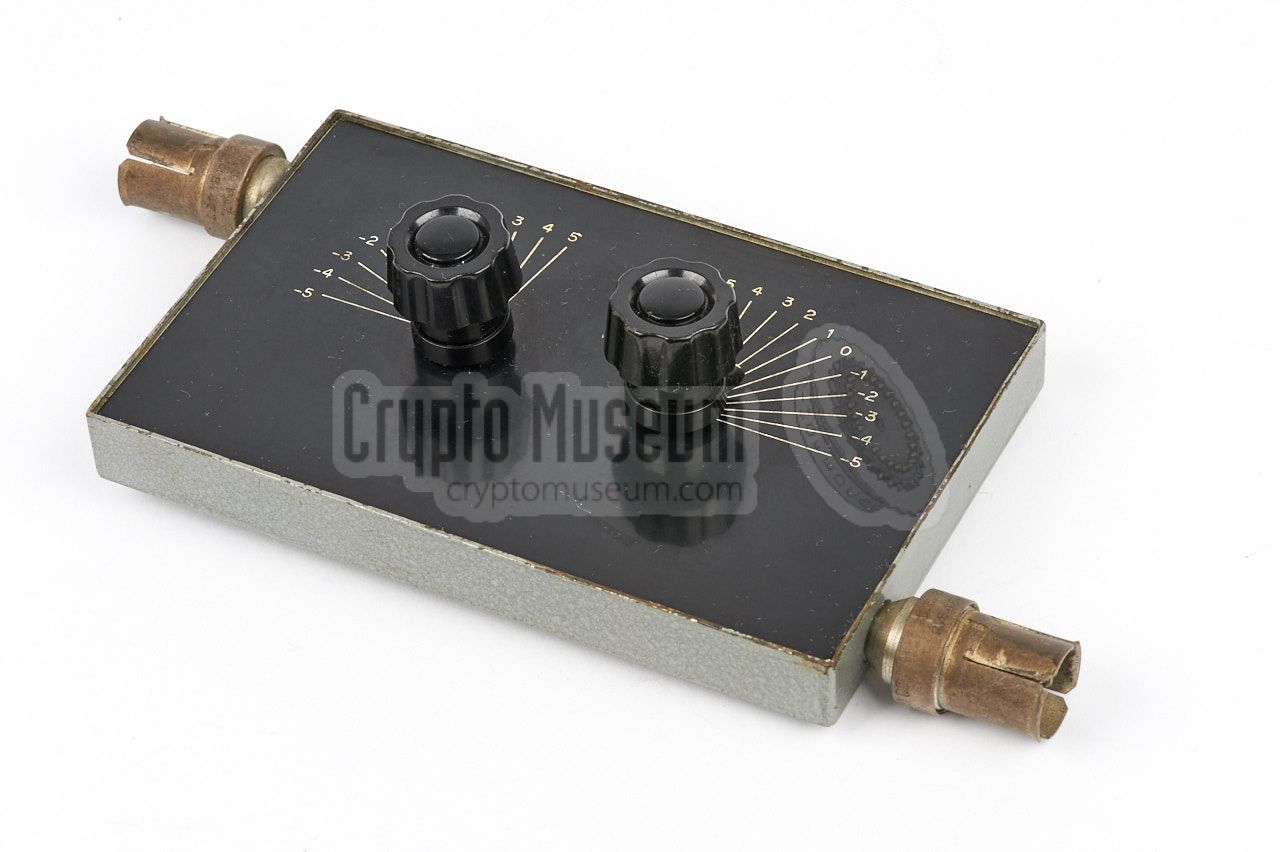
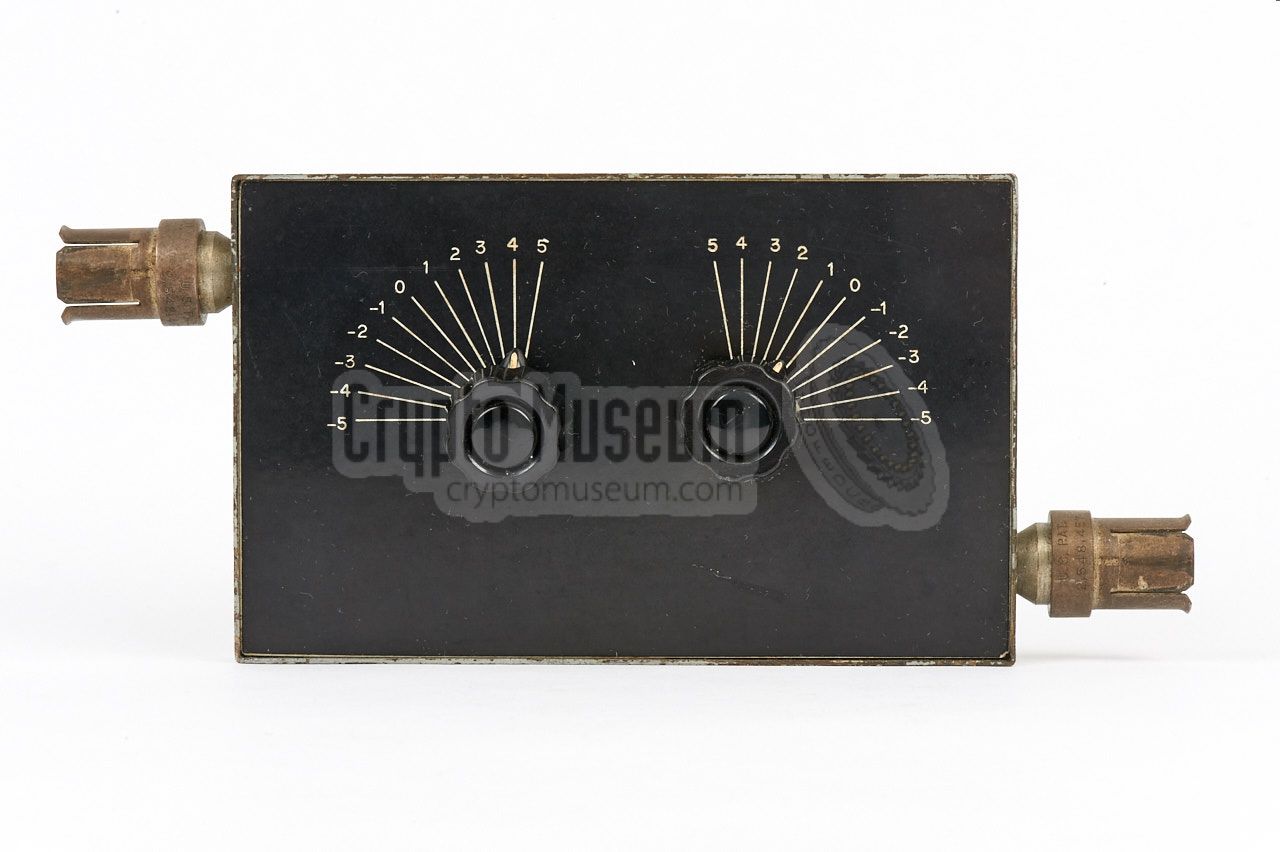
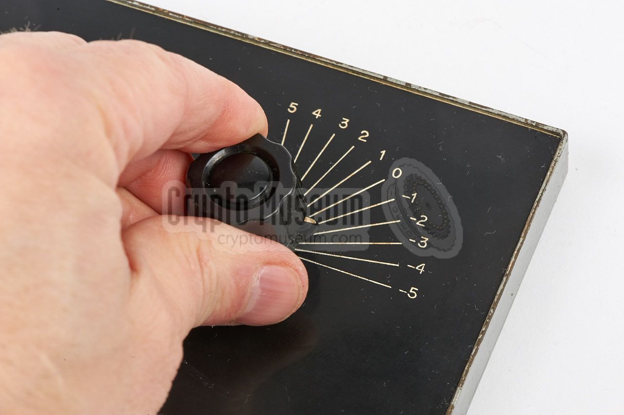
The image on the right shows the antenna matching unit that is visible
at the top right of the block diagram above. It was unique in that,
unlike a common stub tuner, it had no sliding contacts which caused
contact noise. It was suitable for the 300-500 MHz frequency range.
This tuner is probably the only surviving part of an Easy Chair Mark II
listening post. At the center frequency (400 MHz) it had an insertion
loss of just 0.03 dB [C].
➤ Read the full description
|
|
|
Frequency 300-500 MHz Insertion loss 0.03 dB (@ 400 MHz) VSWR 1 (@ 400 MHz)
|
|
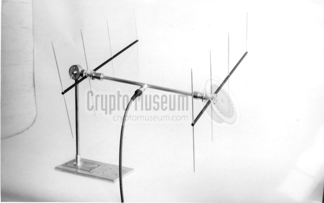
Due to the use of a duplexer, the EC II uses a single antenna for
transmitter and receiver. In order to compensate for the losses of the
duplexer, the antenna gain has to be as high as possible. For this reason,
two 4-element Yagi antennas are used, coupled by a coaxial T-bar — also
known as a Magic-T — with built-in
1/4λ transformers, in order to guarantee a 50 Ω match at all
times.
|
Gain 15 dB F/B ratio 1 20dB Frequency 378 MHz Bandwidth 30 MHz
|
-
F/B = front-to-back ratio.
|
- NRP/CIA, Collection of documents related to Easy Chair Mark II
Crypto Museum Archive, CM302532 (see above).
|
|
|
|
Any links shown in red are currently unavailable.
If you like the information on this website, why not make a donation?
© Crypto Museum. Created: Friday 10 March 2017. Last changed: Tuesday, 10 March 2026 - 08:31 CET.
|
 |

|
|
|