|
|
|
|
|

|
|
NRP CIA EC EC V → ← EC III
Unlike the EC III,
which used a single antenna at the listening post (LP),
the EC IV uses separate antennas for
transmitter and receiver.
This was done to improve suppression of the reflected transmitter
signal in the receiving path and to extend the range of the system.
Furthermore, it allowed the output power of the transmitter to be
enhanced with an (optional) linear amplifier.
Instead of the EC III's duplex filter, the EC IV had a
cancellation unit
for keeping the transmission signal away from the receiver's input,
based on a sophisticated integrated directional coupler [A].
|
|
|
Like its predecessors, the EC IV operated on 378 MHz, and featured
the same Passive Element (PE)
as the EC III
for installation at the target area (TA).
The complete base station was packed in two large
unobtrusive suitcases, one of which contained the transmitter cabinet.
The other suitcase contained the power supply unit (PSU) and
accessories (cables, headphones, spare fuses, etc.).
The EC-IV was short-lived, as it was replaced a year later, in 1962,
by the completely redesigned and much improved
Easy Chair Mark V (EC V),
of which the development had already been
started in 1960. For this reason, the EC-IV should be seen as a
transitional or temporary solution, that was used until the new EC-V
was ready. The EC V
introduces an increased operational range, a much improved
performance and the simultaneous use of multiple PEs in the same
target area.
|
|
|
Improvements over EASYCHAIR III
|
|
|
|
Compared to the earlier Easy Chair system, the EC IV introduced
the following changes:
|
The diagram below shows the configuration of the EC IV system.
At the left is the Listening Post (LP) that consists of a transmitter,
a receiver and a cancellation unit, all housed in the transmitter
cabinet, plus two identical antennas, one for the transmitter and one
for the receiver. Strong RF signals from the transmitter, reflected on
buildings and other objects, are compensated for in the cancellation unit.
A small pick-up loop in the vicinity of the transmitter
antenna, delivers a small portion of the signal to the receiver's
detector for use as the local oscillator (LO) signal.
At the right is the Target Area (TA) where the Passive Element (PE)
is installed. The PE is powered by the energy picked up by its antenna
and rectified by a detector diode, or crystal. It amplifies
the sound that is picked up by its miniature microphone and Frequency
Modulates (FM) it onto a 100 kHz subcarrier (SC). The resulting signal acts
as a load to the antenna, which causes changes in the amount of energy
absorbed or reflected by the antenna. At the LP, the small changes in
reflected energy are used to recreate the original sound and deliver it to
a pair of headphones.
|
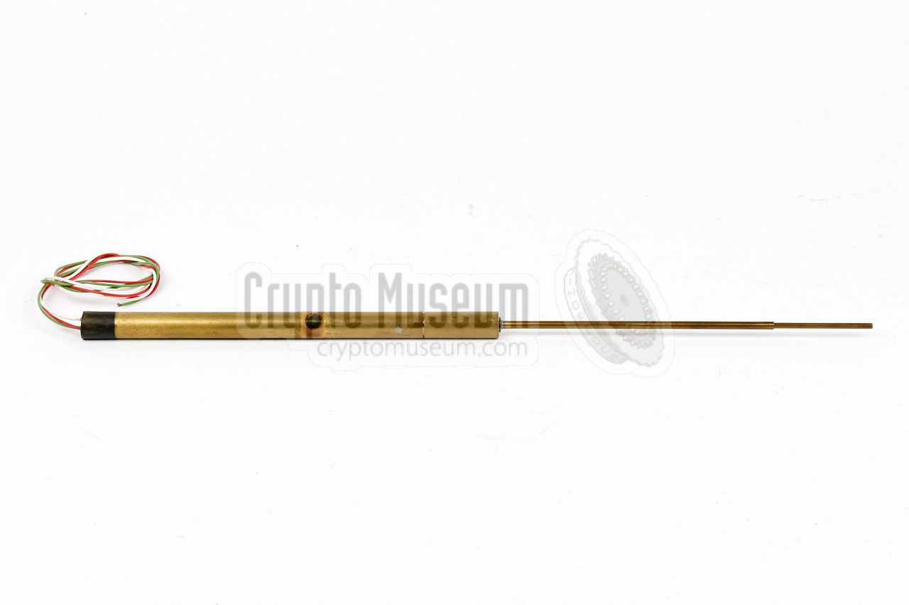
In the EC IV system, the Passive Element (PE) of the EC III is used
at the Target Area (TA). This device does not need a local power
source, but is energized by a strong RF signal beamed at it from the
nearby Listening Post (LP).
The PE consists of a half wave dipole antenna with a thin and a thick
arm, and a diode detector at the centre. The thick part contains a small
transistor amplifier, which modulates the signal from an external
microphone onto a 100 kHz subcarrier using Frequency Modulation (FM).
➤ More about the PE
|
|
|
The basic transmitter, or exciter, was identical to that of the
EC III, and produced a variable output power between 1 and 50 Watts.
This output power could be supplied directly to the transmitting antenna,
or to a linear amplifier, also known as a power amplifier (PA),
to any desired higher power value, probably in the range of 300 to 500 Watts.
Here is the block diagram:
The transmitter is completely built with valves (tubes).
It consists of a free-running oscillator that is tuned to
the target frequency of approx. 378.5 MHz, just like with the
EC I
and EC III systems.
A small portion of the energy from the antenna
is extracted by means of a pickup loop that is placed in the vicinity
of the transmitter, and fed directly to the
Local Oscillator (LO) input of the receiver, where it is mixed
with the incoming signal from the Passive Element (PE).
|
The receiver is a hybrid of valve and transistor technology.
The first two stages - the AM diode detector and the first amplifier -
are built with valves, as they are more tolerant to excessive signals.
The remainder of the receiver (i.e. the IF and AF stages) are built
with silicon transistors.
In many respects, the receiver can be seen as a redesign of the EC III
receiver. The first two stages (here shown in blue) are built with
valves (tubes), whilst the remainder of the receiver is built with
transistors. For some reason, the double reception system with 90°
phase shift (for obtaining phase-indifference) was dropped from
the design. It would later be re-introduced in the EC V.
|
The diagram below shows the construction of the cancellation unit,
which is the most important part of the EC IV. It consists
of a double-deck stripline transmission circuit, with the
straight-through connection from antenna to the receiver at the top
(green). At the bottom left (red) is the cancelling signal, that is fed
in from the pickup nearby the transmission antenna.
The majority of this power is dissipated
in the 50Ω terminator at the bottom right (R4),
but a fraction is coupled into
the secondary branch, where most of it is dissipated in the 50Ω
terminator resistor R3.
By causing a small mismatch with the tuning capacitors, a fraction
of the energy in the secondary branch is reflected and delivered at the top right,
at the input of the 7dB directional coupler, where most of it is dissipated in R2.
A small fraction of this energy however, is coupled into the upper branch,
where it is added to the antenna signal and delivered at the receiver's input.
A second function of the
tuning capacitors in the front deck, is to control the phase of the
signal that delivered at the receiver's input, and hence, cancel out
the majority of transmitter spillover.
Note that a small portion of
spillover has to be allowed, in order for the receiver's detector
to function properly. Two meters are provided for measuring the amount
of spillover (top left) and the amount of cancelling power (bottom
right). They should roughly show the same value.
|
At this time, no specific information is available
about the antennas that were used at the LP.
It is likely however, that they were similar
to the antennas used with the later
Easy Chair Mark V system. Basically, each antenna
consists of a 5- or 6-element Yagi with a corner reflector.
Two or four such antennas were sometimes combined using a Magic-T,
or coaxial-T, in order to obtain a higher gain.
For further information, please refer to the
EC V's LP antennas.
➤ More about the antennas
|
- NRP/CIA, Collection of documents related to Easy Chair Mark IV
Crypto Museum Archive, CM302534 (see above).
|
|
|
|
Any links shown in red are currently unavailable.
If you like the information on this website, why not make a donation?
© Crypto Museum. Created: Friday 10 March 2017. Last changed: Tuesday, 06 June 2023 - 12:39 CET.
|
 |

|
|
|