|
|
|
|
|

|
|
Germany SBO W&G BND SP-15 →
BND AM/CW backup receiver
BN-48, codename UHU, is a miniature shortwave AM/CW
all-transistor receiver, developed in the mid-1950s by
Wandel & Goltermann
in Reutlingen (Germany) for the German intelligence service
Bundesnachrichtendienst (BND).
Introduced in 1958, it was sometimes supplied as part of the
SP-15 spy radio set,
as a backup for the existing FE-8 (BN-58) receiver.
It covers the 2 to 9 MHz frequency band.
Many thanks to Jim Meyer for supplying background
information and images [1].
|
The unit measures approx. 145 x 95 x 40 mm and is housed in a metal
hammerite-painted enclosure. The case is water resistant and
rubber gaskets
are used to protect the circuitry from moisture.
The receiver is primarily built around the
AF125; one of the earliest Germanium HF transtors that were
also used in its 'big brother' the FE-8 receiver (BN-58).
Circuit diagram here.
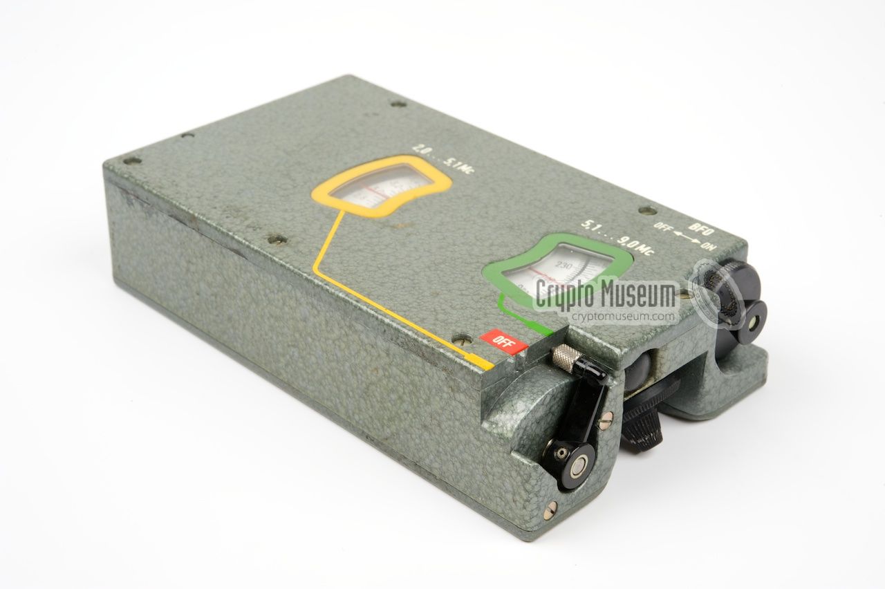
The image on the right show a typical UHU receiver [1].
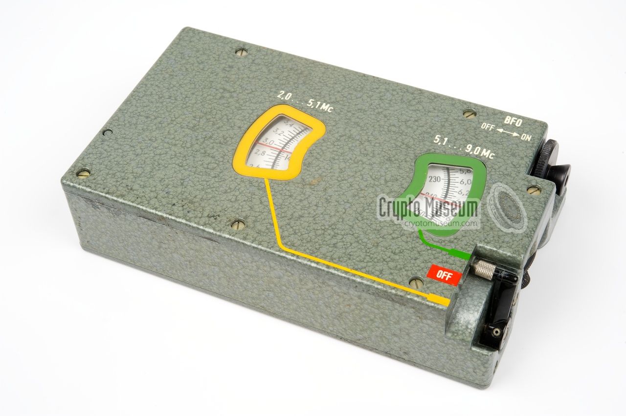
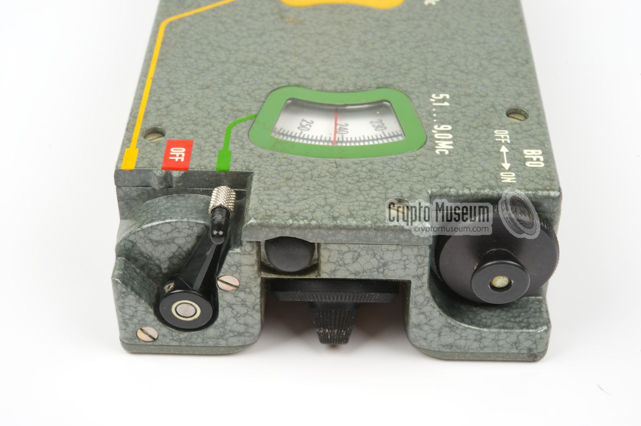
On the top surface are the frequency scales.
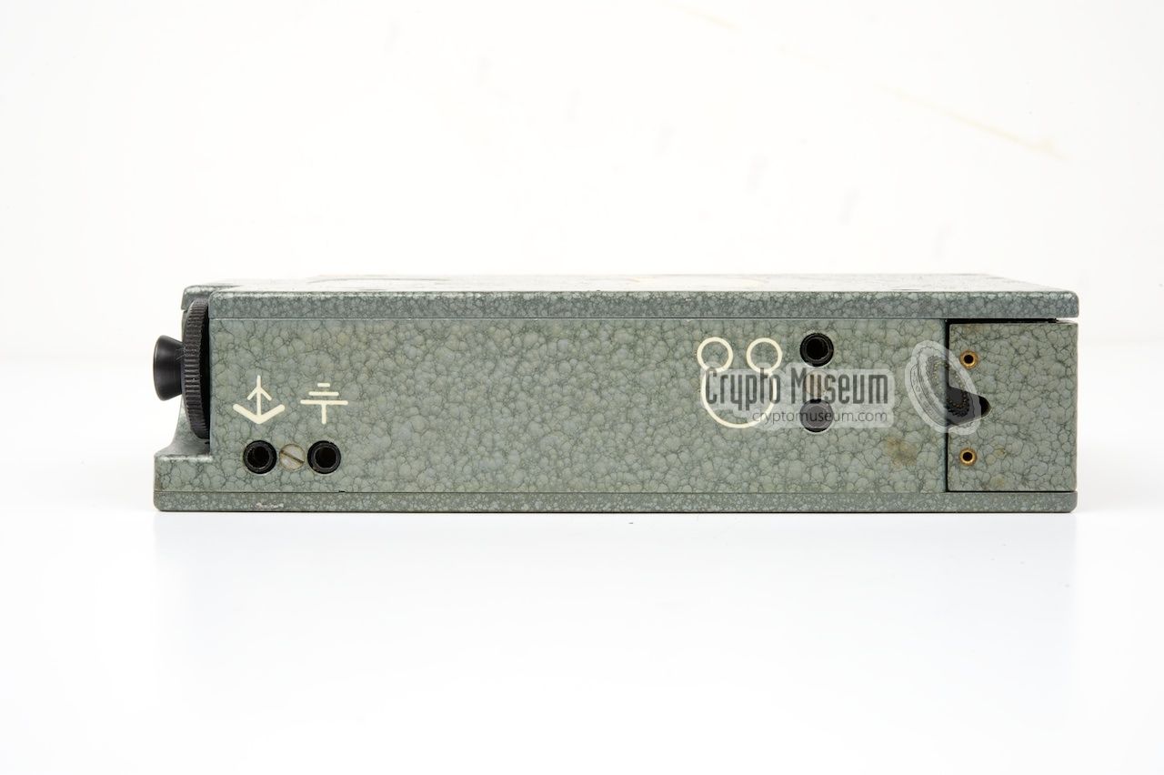
All connections are at the rear,
whilst the controls are on the side panel
at the right.
|
|
|
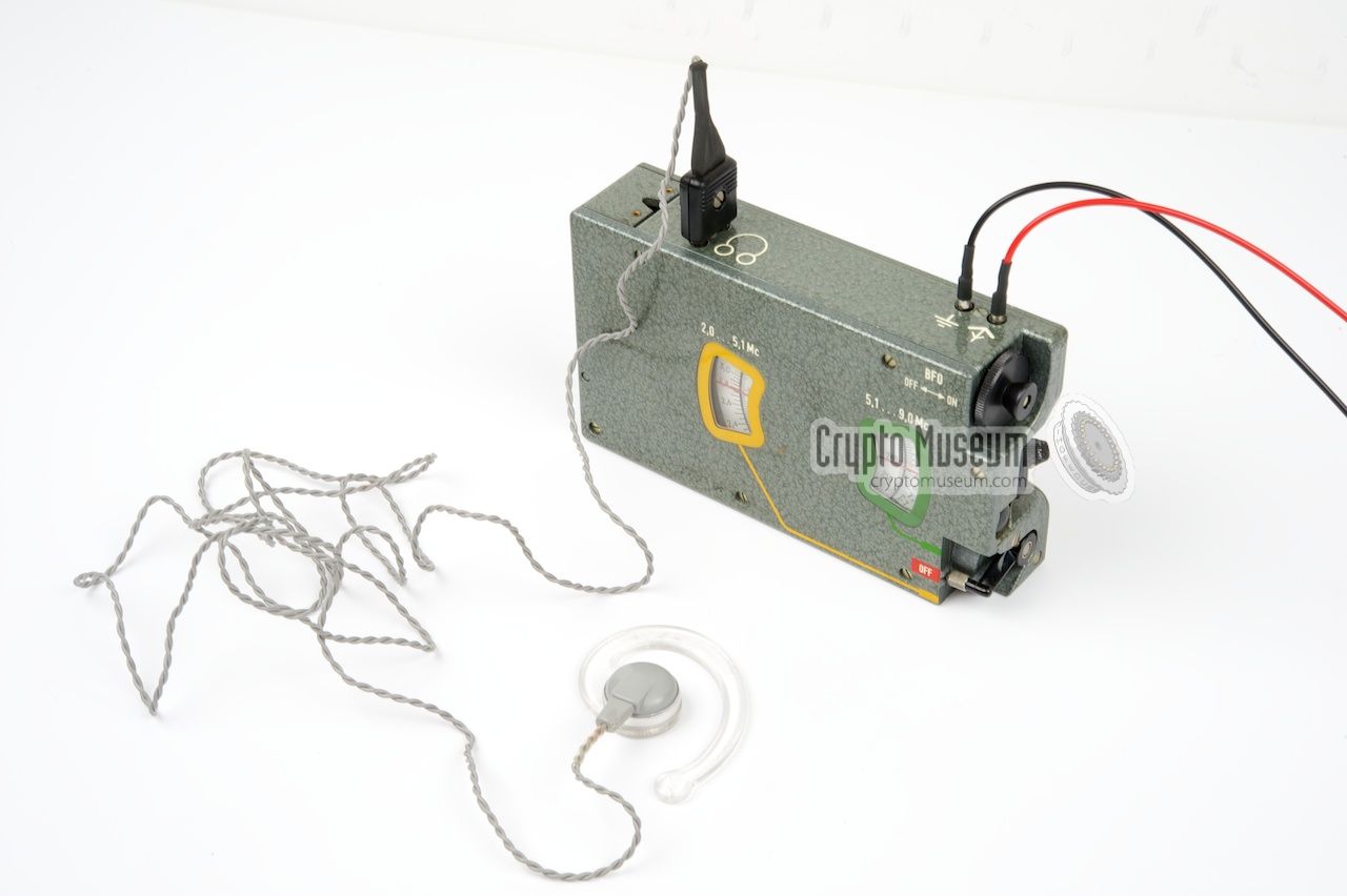
Antenna and ground wires are connected to the
2.5 mm banana-type sockets at the rear panel.
A couple of meters each will be sufficient for good
reception. The free running Variable Frequency Oscillator (VFO) is not
as stable as the later synthesizer-based alternatives, but it is good
enough for the reception of the AM and CW signals (the
famous number stations) that were operated
by the German intelligence service
BND (Bundesnachrichtendienst)
during the Cold War.
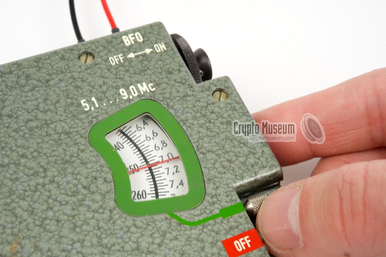
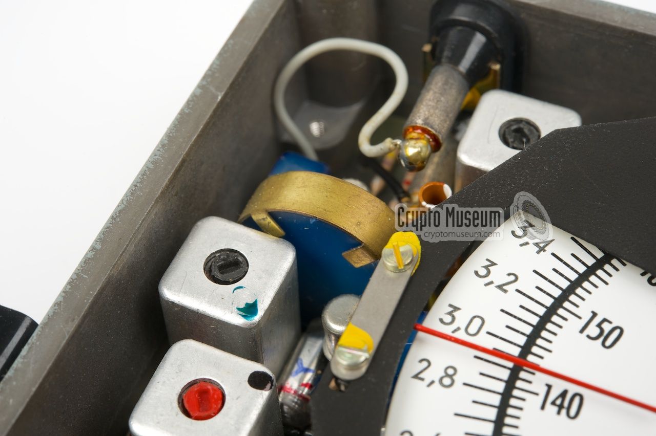
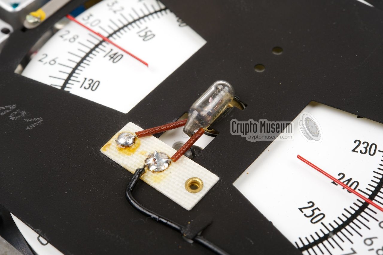
Despite its simple circuit, the receiver has a remarkable
sensitivity and an accurate scale.
|
|
|
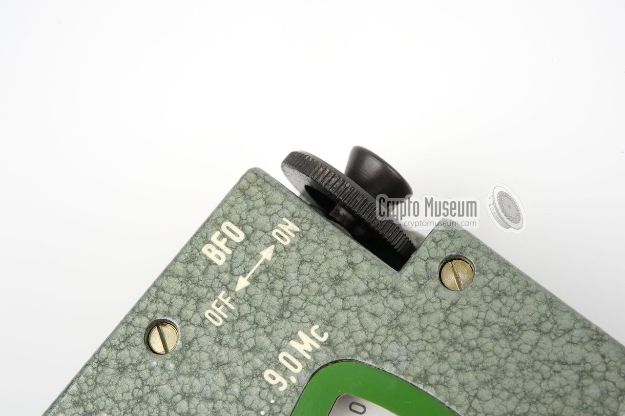
For the 2nd IF stage, a 455 kHz ceramic filter
is used. For the reception of CW signals (morse),
the built-in Beat Frequency Oscillator (BFO) can be switched ON by
pulling the volume knob outwards.
Approximately 600 UHU/BN-48 receivers were built for the BND
by Wandel & Goltermann [3].
The receiver would still be useful today, for example as part of
an amateur QRP station!
|
The UHU receiver was sometimes supplied as an extra receiver
with the SP-15 spy radio set.
The image below shows the suitcase version of the SP-15 in which
the UHU is strapped-in in the right half of the case (at the front left),
next to its 'big brother' the FE-8 (BN-58) receiver.
Also in the right half is a power supply unit (PSU)
and an RT-3 burst encoder.
The latter was used to send messages
in morse code at very high speed in order to minimize the risk
of interception and detection. The left half of the case contains
the usual components of the SP-15 set: the mains transformer,
a battery adapter, the transmitter and the headphones and cables.
➤ More about the SP-15
|
|
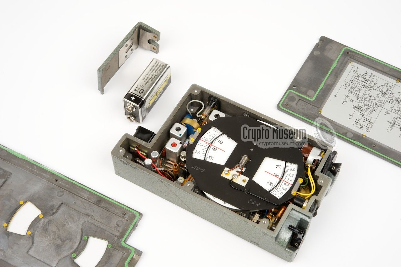
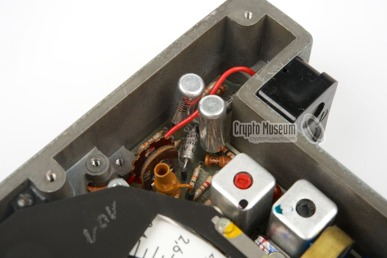
The BN-48 (UHU) is housed inside a purpose-built die-cast aluminium
enclosure that is painted grey hammerite. The interior can easily
be accessed by removing the top and bottom panels, each of which is
held in place by 6 small screws.
Attention: Be careful when removing the top panel.
|
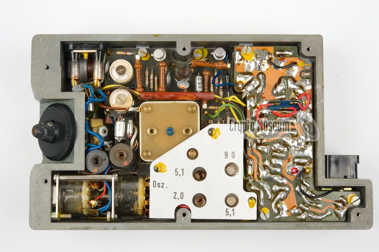
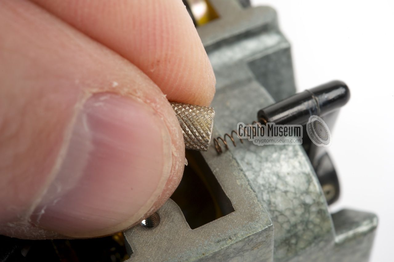
Turning the unit over, reveals the bottom side
of the receiver. At the centre is the
large tuning capacitor that is operated
by the tuning dial at the left. Just below the tuning capacitor are
four adjustments, accessible through four holes in a metal cover.
These are for calibrating the upper and lower ends of each band.
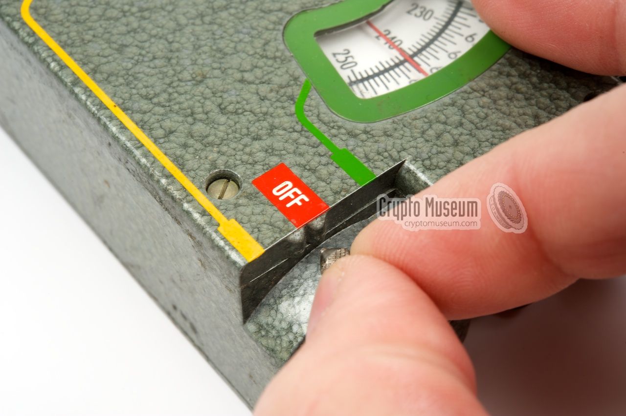
At the bottom left is the power switch/band selector.
Note that high-quality epoxy PCB material is used, which is quite
remarkable given its age (1958).
|
The image below shows the circuit diagram of the BN-48 as it is
printed inside the bottom cover of the case.
The circuit is built two early transistor types: the AF125 (6 pieces) – a PNP
germanium type – for the RF stages,
and the BCZ10 (3 pieces) – an PNP silicon type – for the
AF stages.
From the antenna at the top left, the signal is fed through a bandpass
filter onto the HF amplifier (T1). The amplified signal is then
mixed (T3) with the signal from the local oscillator (T2).
The IF signal is first amplified (T4) and then passed to (T5) via a
455 kHz ceramic filter. The optional signal from the BFO (T6) is
inserted at the base of T5. The output from T5 is first detected (OA95)
and then amplified to earphone level (T8 and T9). The output from the
detector is also used to drive the Automatic Gain Control (AGC, T7).
Audio volume adjustement is at the bottom left and affects the AGC feedback
line. The circuit is powered by a simple 9V block battery.
Half of the tuning capacitor is at the bottom of the local oscillator.
It works in tandem with the band filter capacitor at the top left.
This allows the band filter to be as narrow as possible, making the
receiver much less prone to interference from strong signals on adjacent
channels.
|
|
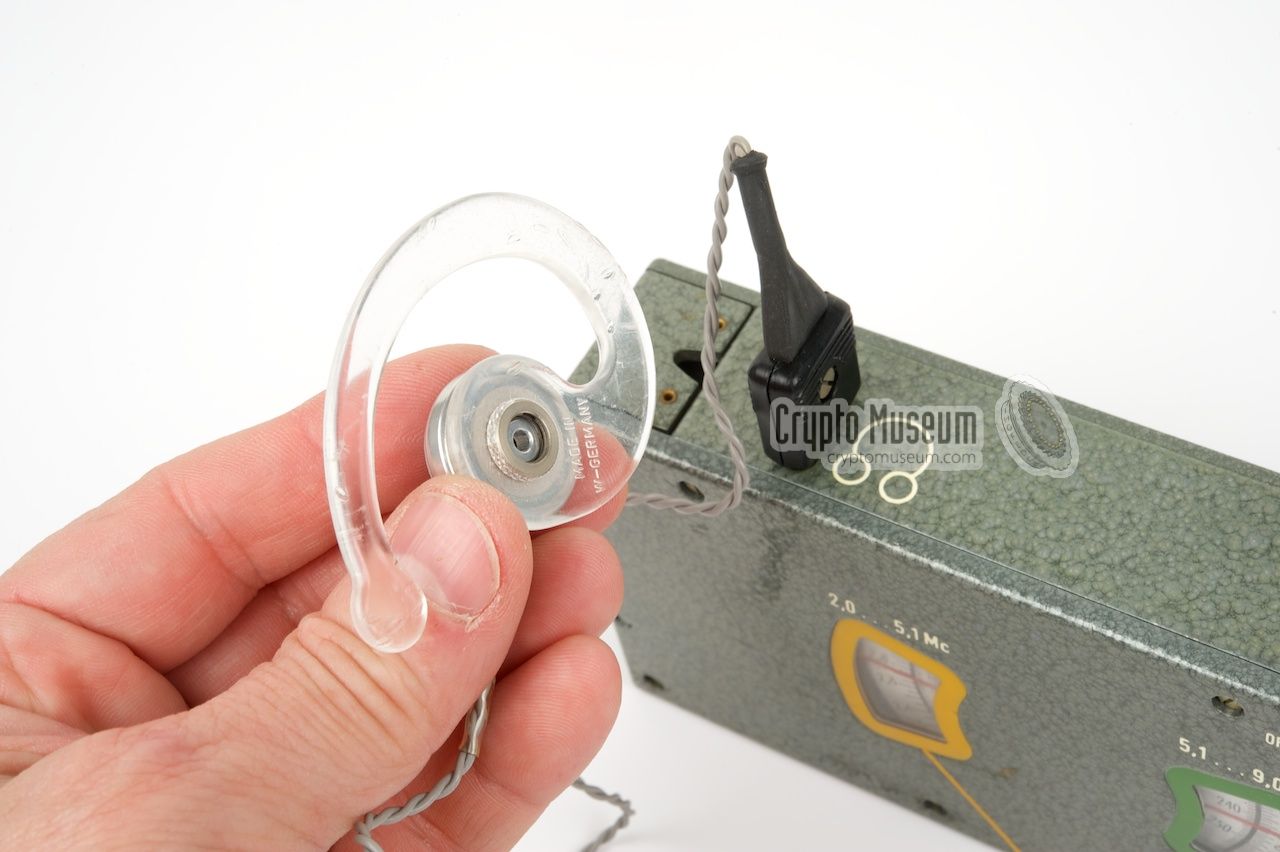
The BN-48 came with the following accessories:
|
- Rechargeable 9V NiCd battery
- Mains battery charger
- Reel with antenna and counterpoise wires
- Earphone
|
Device Portable short wave receiver Purpose Stay-behind backup receiver Model BN-48 Codename UHU Year 1958 Country Germany Manufacturer Wandel & Goltermann User Bundesnachrichtendienst (BND) Type Superheterodyne Frequency 2 - 9 MHz Bands 2 (see below) Circuits RF amplifier, Mixer, VFO, IF amplifier, BFO, AGC, AF amplifier Transistors AF125 (6x), BCZ10 (3x) Power 9V DC (internal battery) Dimensions 145 x 95 x 40 mm
|
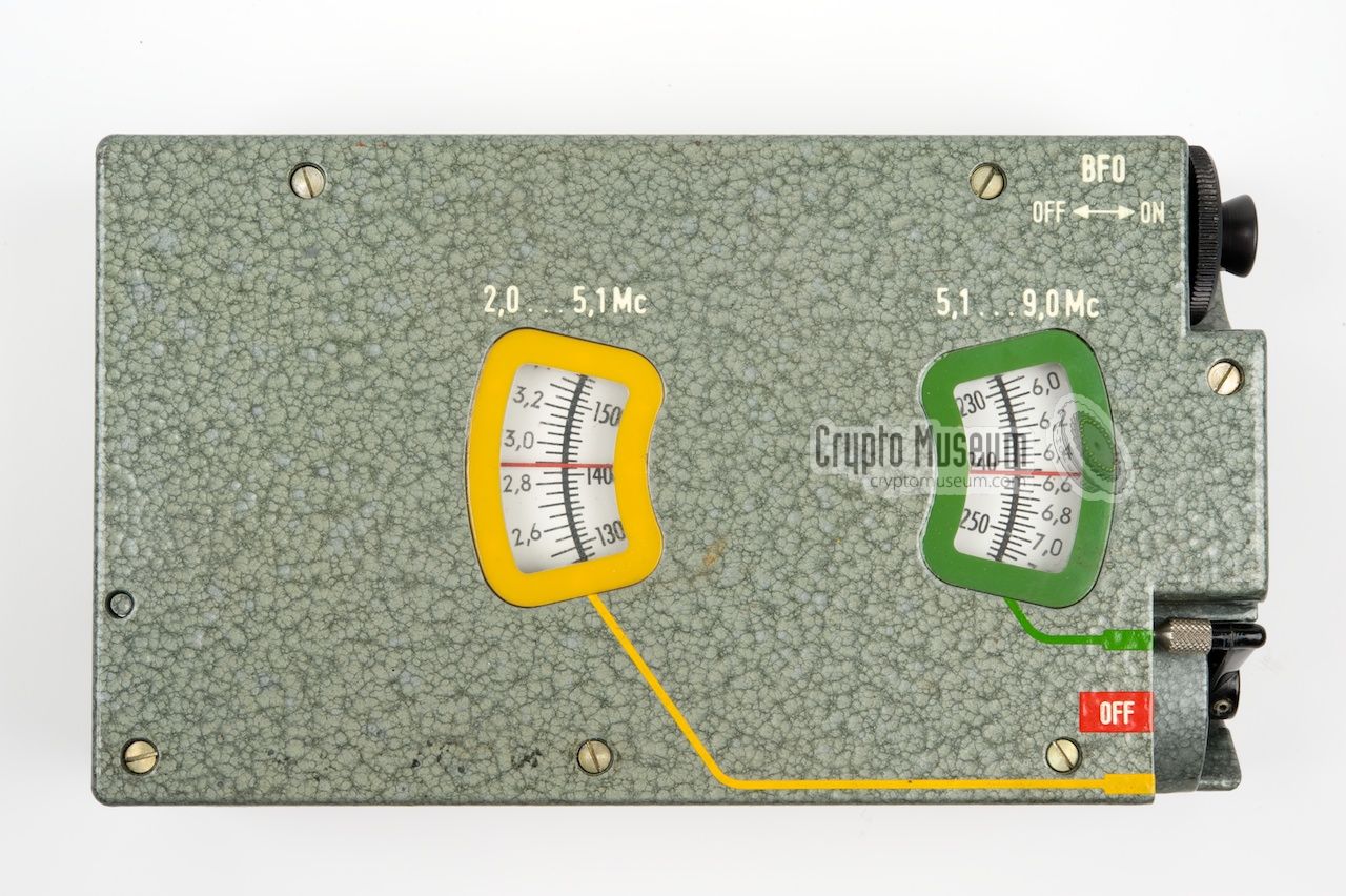
- 2 - 5.1 MHz (yellow)
- 5.1 - 9 MHz (green)
|
|
|
|
Any links shown in red are currently unavailable.
If you like the information on this website, why not make a donation?
© Crypto Museum. Created: Monday 12 January 2015. Last changed: Wednesday, 07 January 2026 - 21:38 CET.
|
 |

|
|
|