|
|
|
|
|

|
Electromechnical burst encoder
The RT-3 is an electromechanical burst encoder,
developed by Wandel & Goltermann in Germany around 1958
for the Bundesnachrichtendienst (BND), the German Intelligence Agency.
It was used in combination with the SP-15 spy set
but also with the SP-20.
It allows a series of 25 pre-recorded numbers to be transmitted at high
speed in morse code.
The abbreviation RT probably stands for Rapid Transmitter.
The RT3 was also used by NATO and by Stay-Behind Organisations.
|
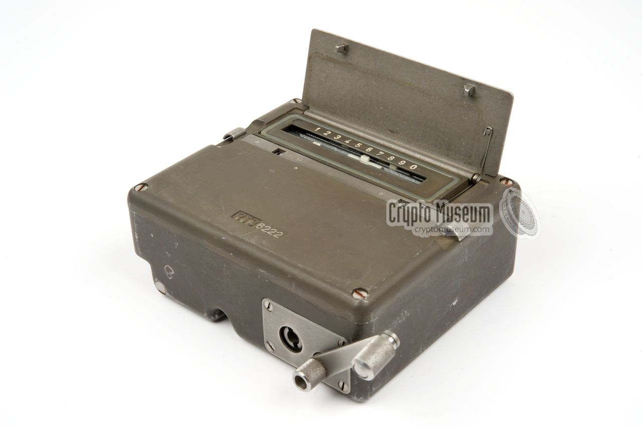
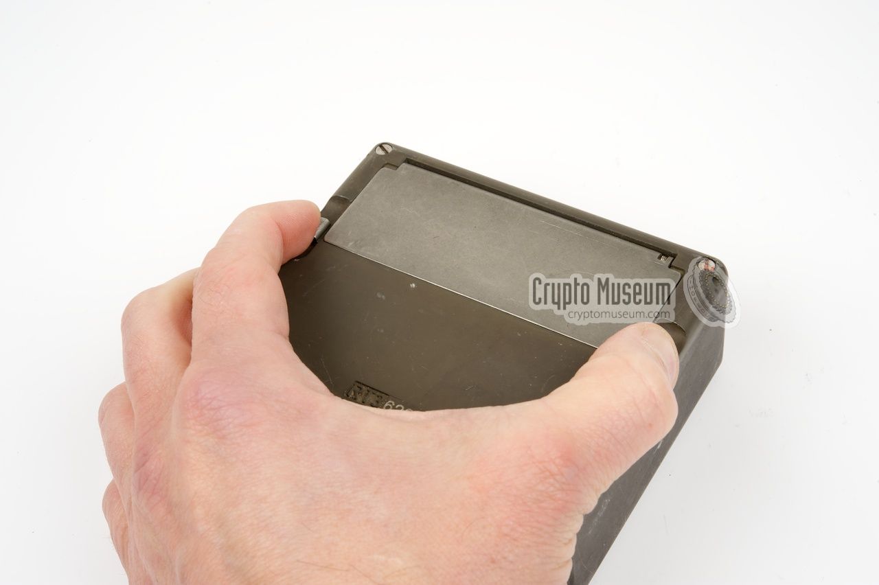
The device is housed in a sturdy military-grade die-cast aluminium case, which is
partly milled out. At the top is a small metal lid that covers the mechanical
memory. The lid is held in place by two locks, one at either side of the
device, that have to be pressed simultaneously in order to get access to the
coding cylinder.
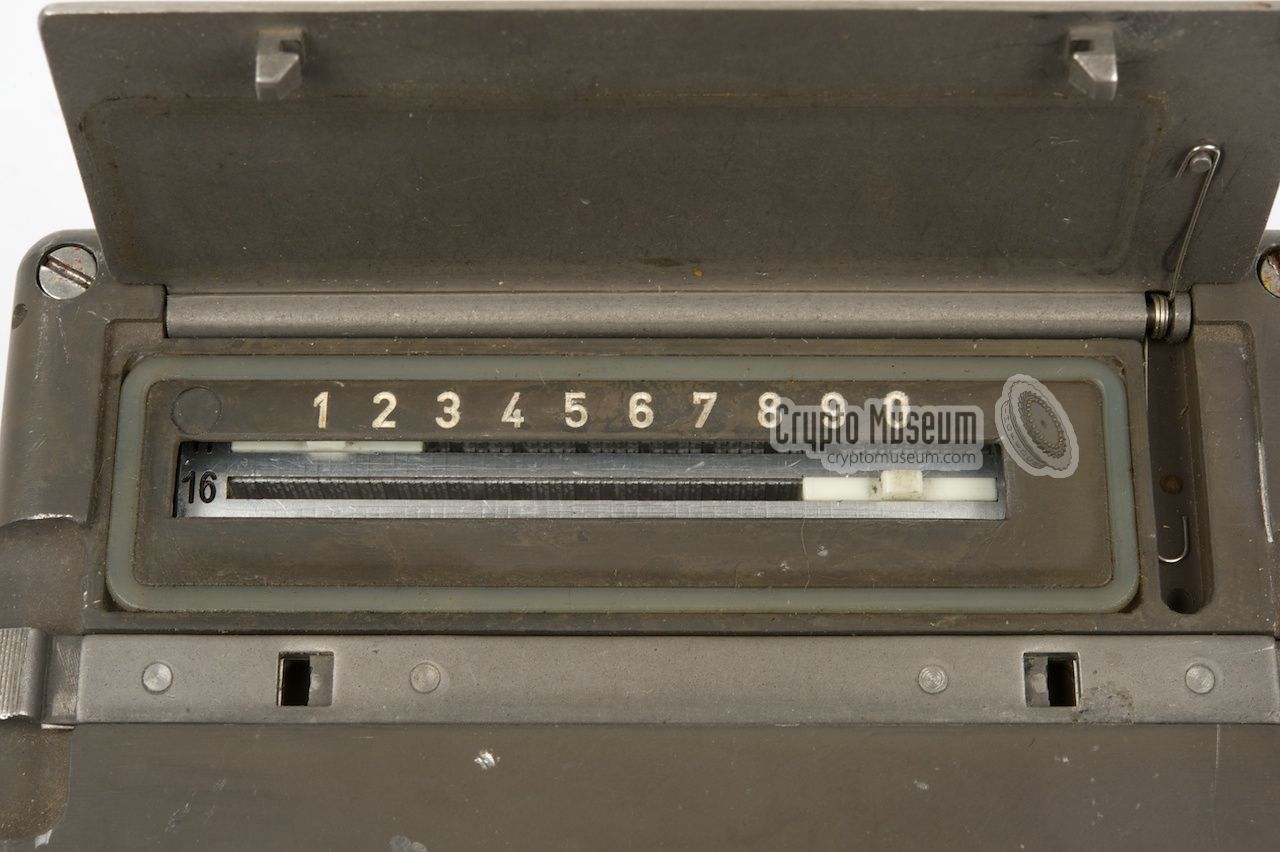
The coding cylinder consists of 25 horizontal bars, each with a movable tab.
The tab can be moved from left to right and click into 10 different
positions. The positions are marked 1, 2, 3, 4, 5, 6, 7, 8, 9 and 0.
|
|
|
All tabs are white, except for bar number 7, which has a red tab. It is used
to indicate the starting position when transmitting a message. Once the message
has been entered, the RT-3 is connected to a transmitter and a hand crank is
used to play back the message at hight speed.
When moving the crank clockwise at a modest - constant - speed, the RT-3 will
transmit characters at approx. 250 words per minute (wpm).
Each RT-3 unit, however, is capable of transmitting the character about
three times as fast, which makes the transmission burst even shorter!
|
The table below shows how the digits 0-9 are interpreted.
The numbers are translated to characters that have more or less the same
length and can easily be distunguised from each other.
The contact cylinder (4) consists of 11 adjacent discs that are milled out
of a solid rod. The leftmost cylinder is the common contact. The other 10
discs are milled out in such a way that the
morse code of the corresponding
character is formed twice around the circumference of the disc.
|
The drawing below shows a cross section of the RT-3, where disc 2 of the
contact cylinder (4) is shown in the neutral position. The coding cylinder
(3) is shown in the starting position with the red tab (#7) at the top and
tab 1 in position before the switch (7). The slide contact (5) rests at an
isolated part of the disc.
|
When the crank is moved, both cylinders start rotating.
The coding cylinder (3) is the slow one; with each full rotation of the crank,
the coding cylinder makes two steps (i.e. two bars).
With each single step of the coding cylinder (3) the contact cylinder (4) makes
one full revolution.
With each full revolution, it sends out the
morse code
for the corresponding character twice.
Each coding disc has 23 faces at its circumference.
Some of these are left intact,
whilst others have been milled out. The milled out gaps have been filled with
some high-grade rock-solid transparent insulating material.
When the disc is rotated, the slide contact either touches the metal on the
outer surface of the disc, or the insulation that fills the gaps.
In the drawing above, the coding disc (4) for tab positon 2 is shown.
As we've seen before, code number 2 is transmitted as morse character F
( · · – · ), which you can see twice on the circumference of the disc (following
the disc counter-clockwise from the switch contact).
|
| |
The latch in the neutral position
|
When the coding cylinder (3) is moved, a tab closes the switch (7) of
the corresponding number (0-9), simply by pushing aside a lever that engages
the switch. As all 10 switches are connected in parallel, and only one tab is
present on each bar, only one morse character is transmitted.
When the contact cylinder is moved from its neutral position,
the latch wheel pushes away the latch bridge. The latch will then be moved down,
locking the current switch lever in place.
|
| |
The latch in the latched position
|
|
The table below shows the layout of the 10 coding discs of the
contact cylinder. The lighter segments in the table are isolated,
whilst the darker parts are contacts. In the initial position (the red
tab visible in the window), the switch contact is at the bottom (position 1).
In this position all contacts are isolated.
As it is rather difficult to position the red tab exactly in the middle of the window,
the next position of the discs (2) and the previous one (23)
are also isolated.
An extra disc on the left is used as a common rail.
All discs are mounted on a shaft and will therefore make contact with
the common disc on the left.
When the cylinder starts rotating, the contacts move over position 2, 3, 4, etc.
until the cylinder is back at position 1 (i.e. a full revolution).
During one revolution, the character is sent twice, as it is present on
the circumference twice. A dot in the
morse code is represented by a single segment,
just like the space between the dots and the dashes.
A dash is either 3 or 4 segments and the space between
two characters is either 2 or 3 segments.
The characters have been chosen to have a more or less equal length.
|
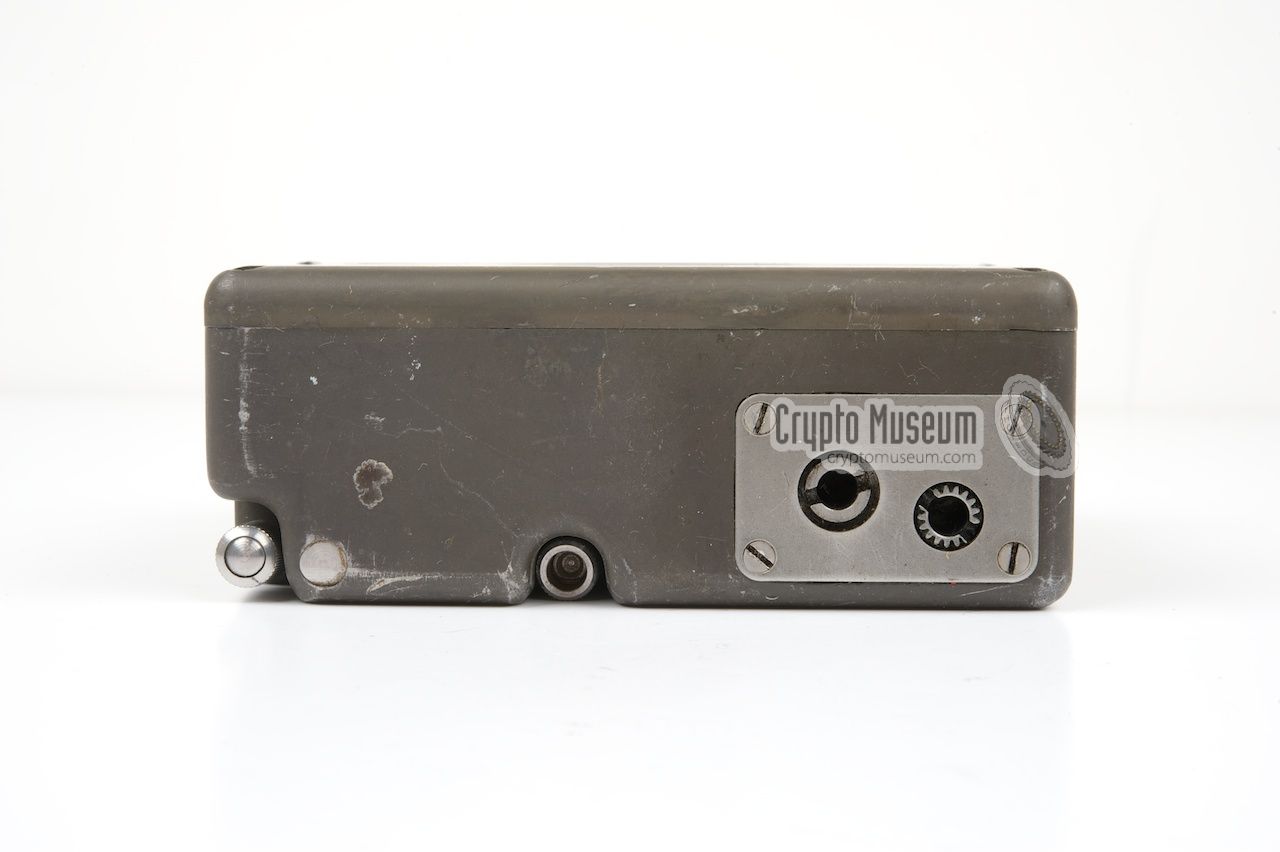
The crank is normally stored in a milled-out cavity at the bottom of the RT-3.
In order to play back a message, the crank is taken out of its storage position
and inserted into a hole at the front of the device. It should then be rotated
manually at constant speed.
As the crank is often missing from the few RT-3 devices that have survived,
we created the drawing shown here. It should be relatively easy to create a
replica. All sizes are in mm.
➤ Download as 1:1 PDF file
|
|
|
|
In order to use the higher speed, a small gear-box is present inside the RT-3
and the hand-crank should be inserted into a second hole (to the left of the
default hole). Please note that in this case, the crank has to be moved
counter-clockwise. Moving it clockwise will have no effect.
|
Also note that at this higher speed it is far more difficult to move the
crank at a constant speed. Furthermore, some transmitters may not work
properly at the higher speed.
For this reason, the leftmost hole of the
gear box is blocked by a small black disc on most RT-3 units.
It is easy, however, to undo this modification by removing the
black disc from the cover plate, as indicated in the drawing.
|
|
|
|
|
RT-3 and the SP-15 spy set
|
|
|
The SP-15 is a complete radio station that was developed in Germany
in the early 1960s by Wandel & Goltermann for the
Bundes Nachrichtendienst (BND). It was intended for agents,
special forces (SF) and stay-behind organisations (Gladio).
➤ More information
|
|
|
|
|
RT-3 and the SP-20 spy set
|
|
|
The SP-20 was developed in Germany by Pfitzner and AEG Telefunken
as a replacement for the SP-15 (see above).
It consisted of a transmitter, a receiver and a synthesizer.
Messages were transmitted in morse
by means of a manual key or
a burst encoder, such as the RT-3.
➤ More information
|
|
|
The electrical circuit diagram is not exactly rocket science, but it is
usefull for a general understanding of the device. As the coding cylinder
of the RT-3 consists of 10 notched discs, there are an equal number of
sensing switches, all of which are connected in parallel (SW0 - SW9).
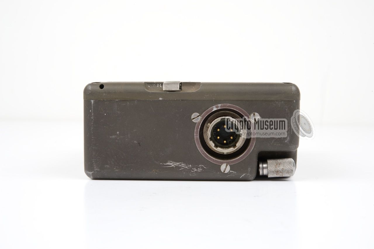
At the bottom is the 6-pin military socket, of which only pins B and F are
used. Pin D is connected to the chassis and is normally tied to pin B
by the wiring.
- not connected
- KEY (-)
- not connected
- GND
- not connected
- KEY (+)
|
|
|
When connecting the RT-3 to the SP-15 spy set, the 5-pin DIN plug
should be wired as indicated in the drawing on the left.
Please note that the wiring is different from the connection of a
standard morse key.
Connection of the RT-3 to the SP-20 spy set is rather simple.
It should be wired as indicated in the drawing on the left.
The RT-3 connects to the SP-20 by means of two standard banana-type
plugs.
|
|
|
|
Any links shown in red are currently unavailable.
If you like the information on this website, why not make a donation?
© Crypto Museum. Created: Wednesday 07 October 2009. Last changed: Monday, 09 May 2022 - 16:00 CET.
|
 |

|
|
|