|
|
|
|
|

|
|
Receivers Germany WWII Abwehr Radione RS-20/M →
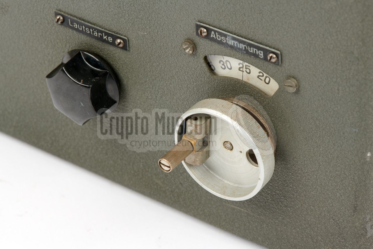
The R3 covers the short wave frequency range of 2.5 - 25.7 MHz
(12 - 120 metres). It is suitable for receiving AM and CW
(morse) signals.
It has a sensitivity of 5-10 µV for AM and 1-2 µV for CW.
The radio is housed in an aluminium enclosure that is very similar to that
of the civil Radione R2 (from 1939) on which it is based. It is built with
6 thermionic valves 1 (vacuum tubes). Unlike the R2 – which has
5 valves – the R3 has a built-in Beat Frequency Oscillator (BFO) for
reception of CW signals. The space for the extra EBC11 valve had already been
reserved on the R2's chassis.
|
|
|
|
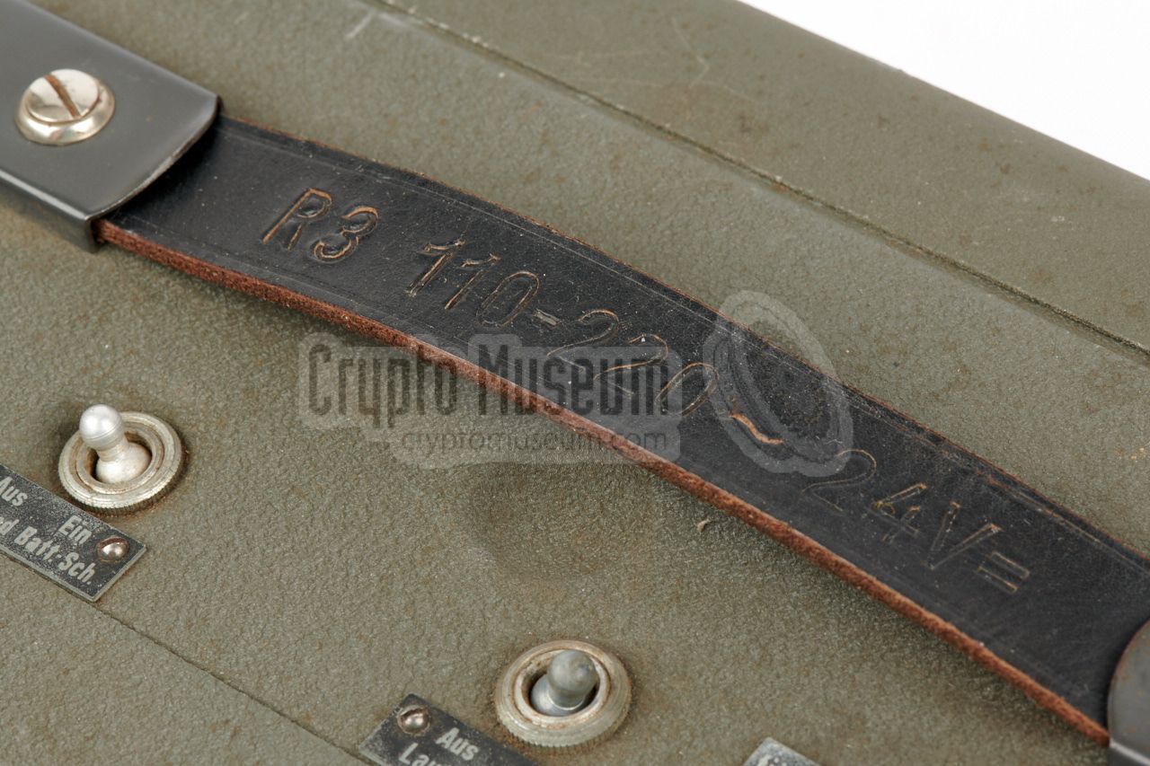
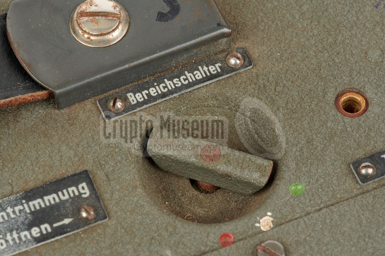
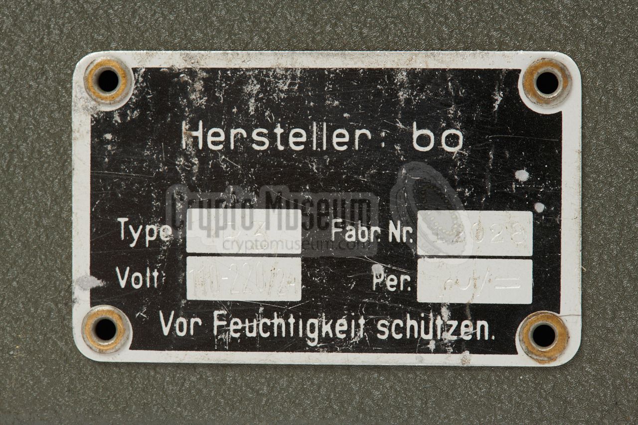
The R3 was available in a number of power variants.
The one shown here has a built-in mains transformer that is
suitable for 120, 150, 190 and 220V AC, using a
special power plug that
can be inserted in four different ways.
It can also be powered by
a 24V DC source, such as the battery of a truck. Other variants were available
for 6V or 12V DC. The voltages were usually impressed in the
leather carrying grip on top of the device.
Unlike other Radione receivers, production of the R3 was discontinued
at the end of WWII, which is why it has since become a rare collectors item.
|
-
Steel valves. German: Stahlröhren.
|
|
Although the most common version of the R3 had three short wave
frequency bands, there are other versions as well, plus a nuber of variants,
including one that has station names on the dial.
Below is a non-exhaustive overview
of the currently known versions and variants of the R3:
|
- R-3
This is the most common version of the R3 receiver. It has
three short wave (SW) bands: (1) 2.5 - 6.7 MHz, (2) 6.7 - 14.8 MHz
and (3) 14.8 - 25.7 MHz. The device was available in a 6, 12 and 24V
variant. The voltage was usually added to the model number:
R3-6V, R3-12V and R3-24V.
The device featured here, is the R3-24V.
- R-3A
This version was for 6V DC only. No further information about this type
is currently available.
- R-3B Mk. I 1
This version was for 6V DC only and had two frequency bands: (1)
200 - 529 kHz and (2) 500 - 1550 kHz.
It is also known as the LW/MW version.
- R-3B Mk II 1
This version was for 6V DC only and had three short wave bands,
but the frequencies are currently unknown.
- R-3b
Version with 3 shortwave (SW) band, without mains power supply.
|
-
The designators 'Mk. I' and 'Mk. II' have been added by us to identify
the different variants. They were not used by the manufacturer and are
not printed on the device's ID plate.
|
|
The Radione R3 was a universal semi-portable shortwave receiver that was
suitable for a wide variety of applications. Here are some examples of
its users:
|
- Wehrmacht
During WWII, the German Army (Wehrmacht) used the Radione R3 receiver
and the RS-20/M transmitter for mobile installations,
for example in bunkers (see below).
- Kriegsmarine
The R3 was used by the German Navy (Kriegsmarine) for use aboard
small vessels, often in combination with the
Radione RS-20/M transmitter,
or with the Lorenz Lo40K39f.
- U-Boat
The Radione R3 receiver and RS-20/M transmitter
were also used by the
U-Boat section of the Kriegsmarine for backup purposes, and for troops
that were landed ashore for special operations (commandos).
➤ Trivia: The R3 is visible in the movie Das Boot
➤ Wikipedia.
- Abwehr
The German Intelligence Service, the Abwehr,
used the R-3/RS-20M as a small commando station [1].
The R3 was also used as a stationary receiver in some head-end stations
of the Abwehr, commonly in combination
with an existing transmitter like the S-87/20
[2].
- Sicherheitsdienst (SD)
Another WWII German secret service, the Sicherheitsdienst or SD
(security service), also used the Radione R3. Examples are
secret agent Richard Kauder (codename: Klatt), who used it in Sofia (Bulgaria),
and Franz Mayr, who used it in Tehran (Persia, now: Iran) [4].
|
It is often thought that the Radione Radio Set was only used by the German
Navy (Kriegsmarine), but the image below — taken in a wartime bunker —
proves that it was also used by the German Army (Wehrmacht). At the far
right is the Radione RS-20M transmitter,
which is used here in AM mode (phone). To its left is the Radione R3.
At the far left is a DR-78 transceiver made by
Philips.
According to Norwegian collector Jørgen Fastner, it is also possible that
this picture was taken in a Coastal Artillery bunker, in which case
it has to be attributed to the Navy (Kriegsmarine) [6].
|
|
Within the
German Intelligence Service, the Abwehr,
the combination R-3/RS-20M
was known as Kleinabwehrstelle (small
defense station). It was generally used between 3 MHz and 6.5 MHz for
intelligence operations (Abwehrkommandos), mainly in foreign countries
behind enemy lines [1].
|
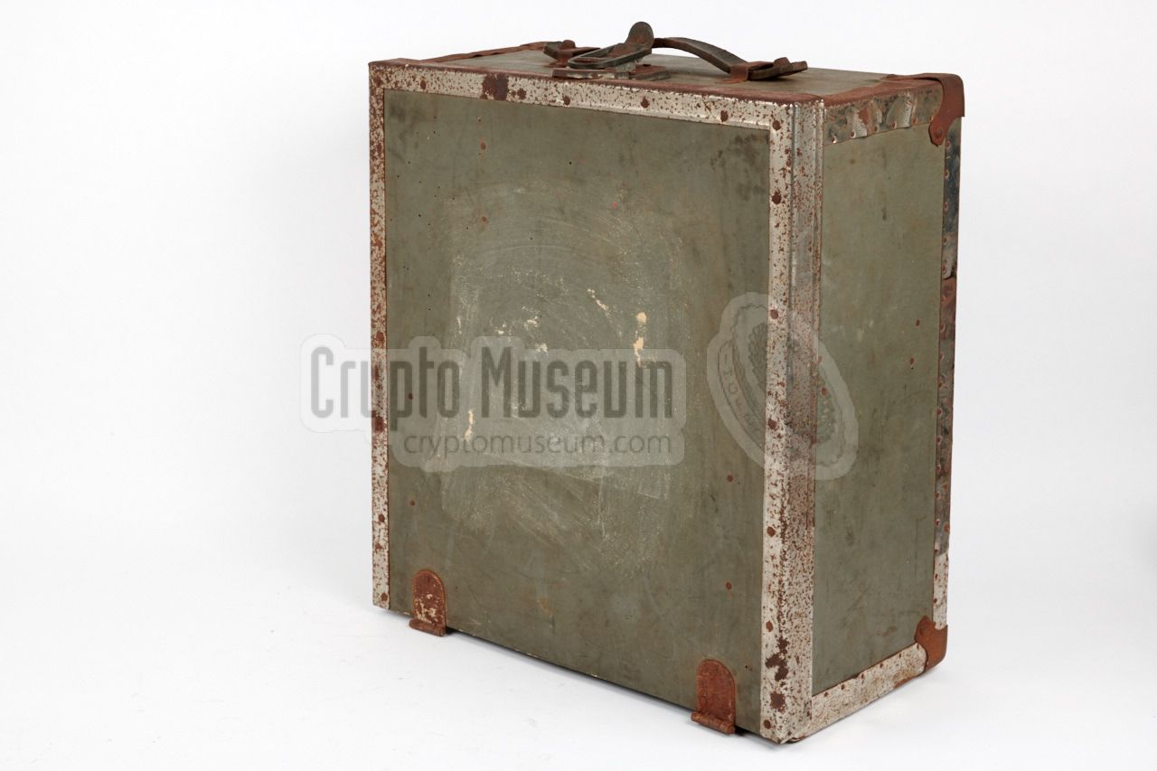
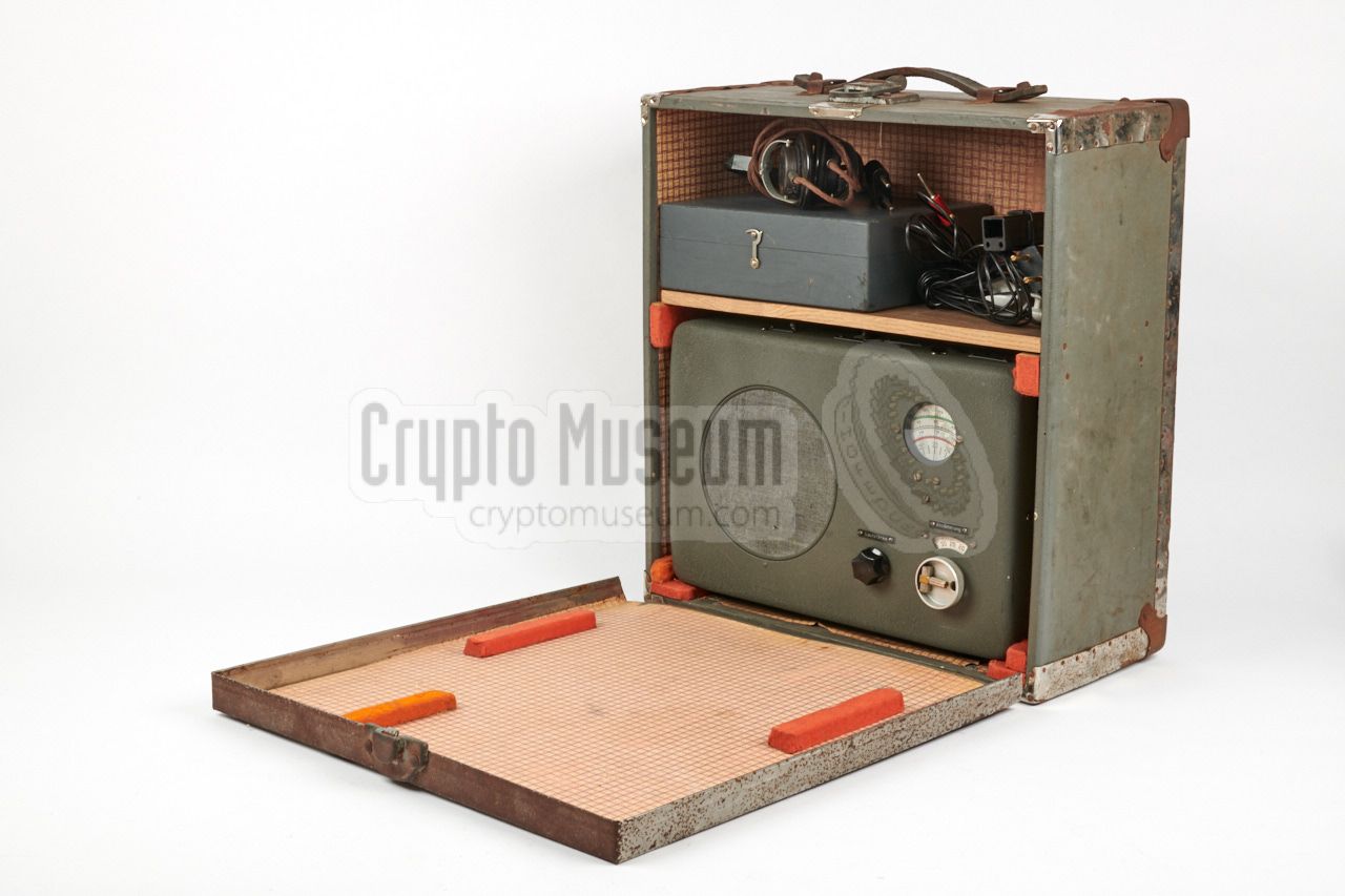
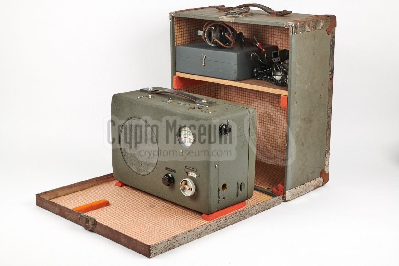
The R3 was distributed in a large wooden transport case
that measures 45 x 41 x 19 cm and weighs over 15 kg,
the radio included.
At the front is a lid that is fixed with two hinges at the
bottom and a heavy lock at the top. After unlocking the lid,
it can be lowered as shown in the image on the right. In order
to connect and operate the radio, it has to be removed from
its storage position. A similar case was used for the
complementary RS-20M transmitter.
|
|
|
The actual Radione R3 is stored in the large compartment
at the lower half of the transport case. Rather than operating
it standing on the lid of the transport case, it was usually
placed on a table or desk, along with a suitable transmitter,
whilst the transport case was stowed elsewhere.
The radio measures 350 x 240 x 175 mm and weighs approx. 11 kg.
It can be operated from the AC mains, or from a suitable DC
source.
|
|
|
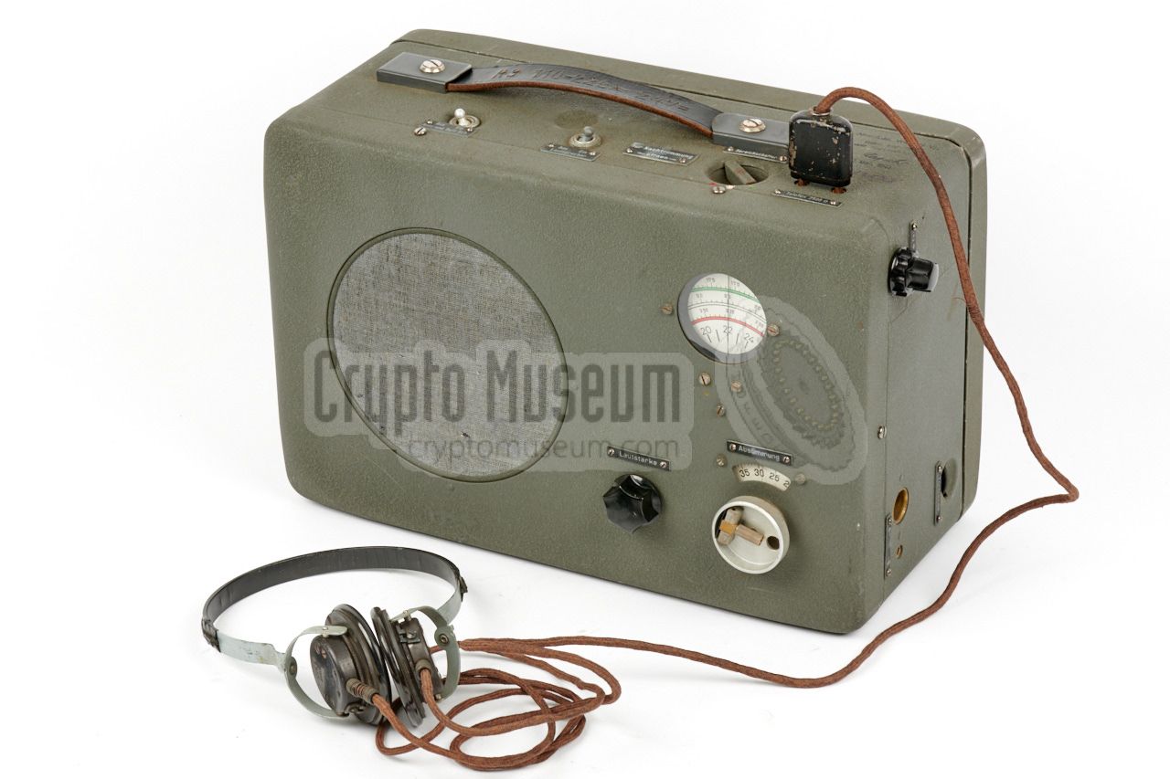
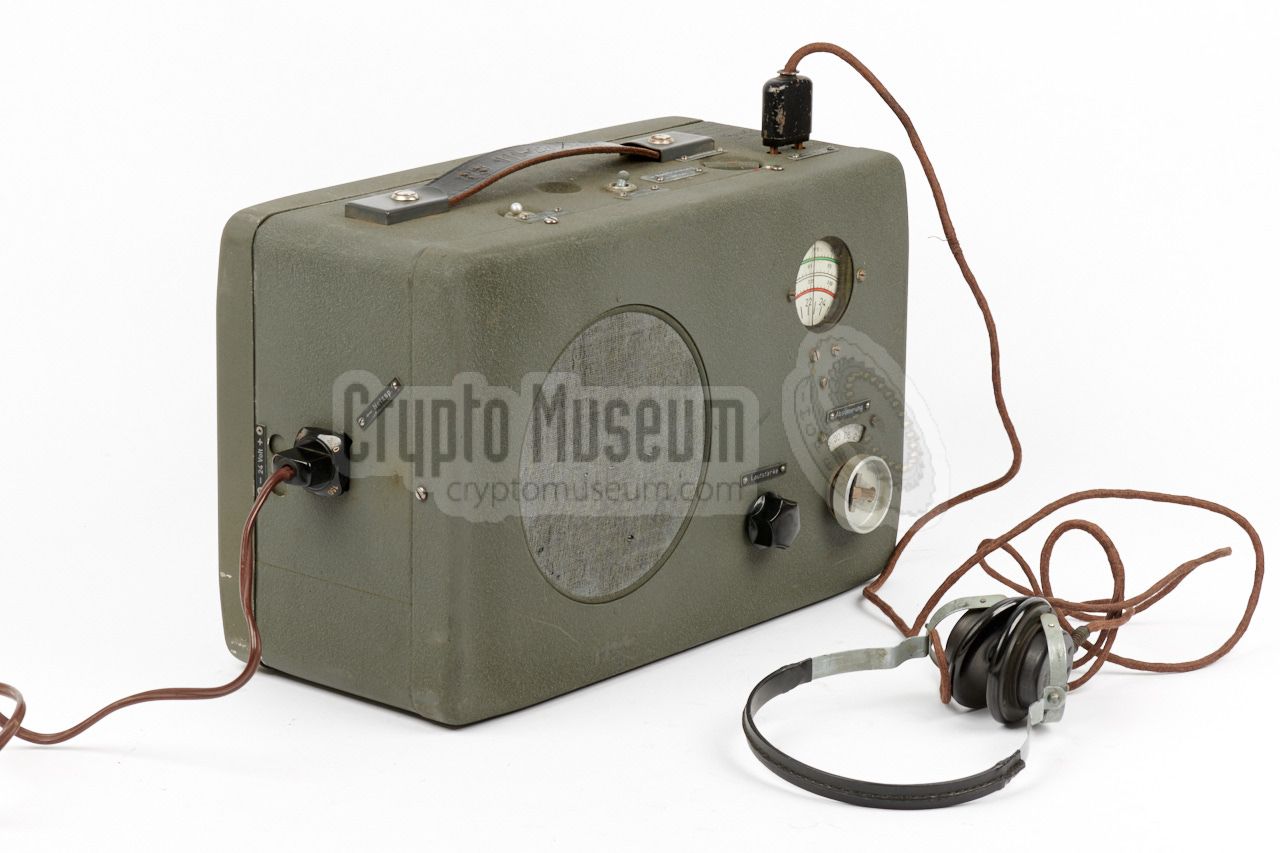
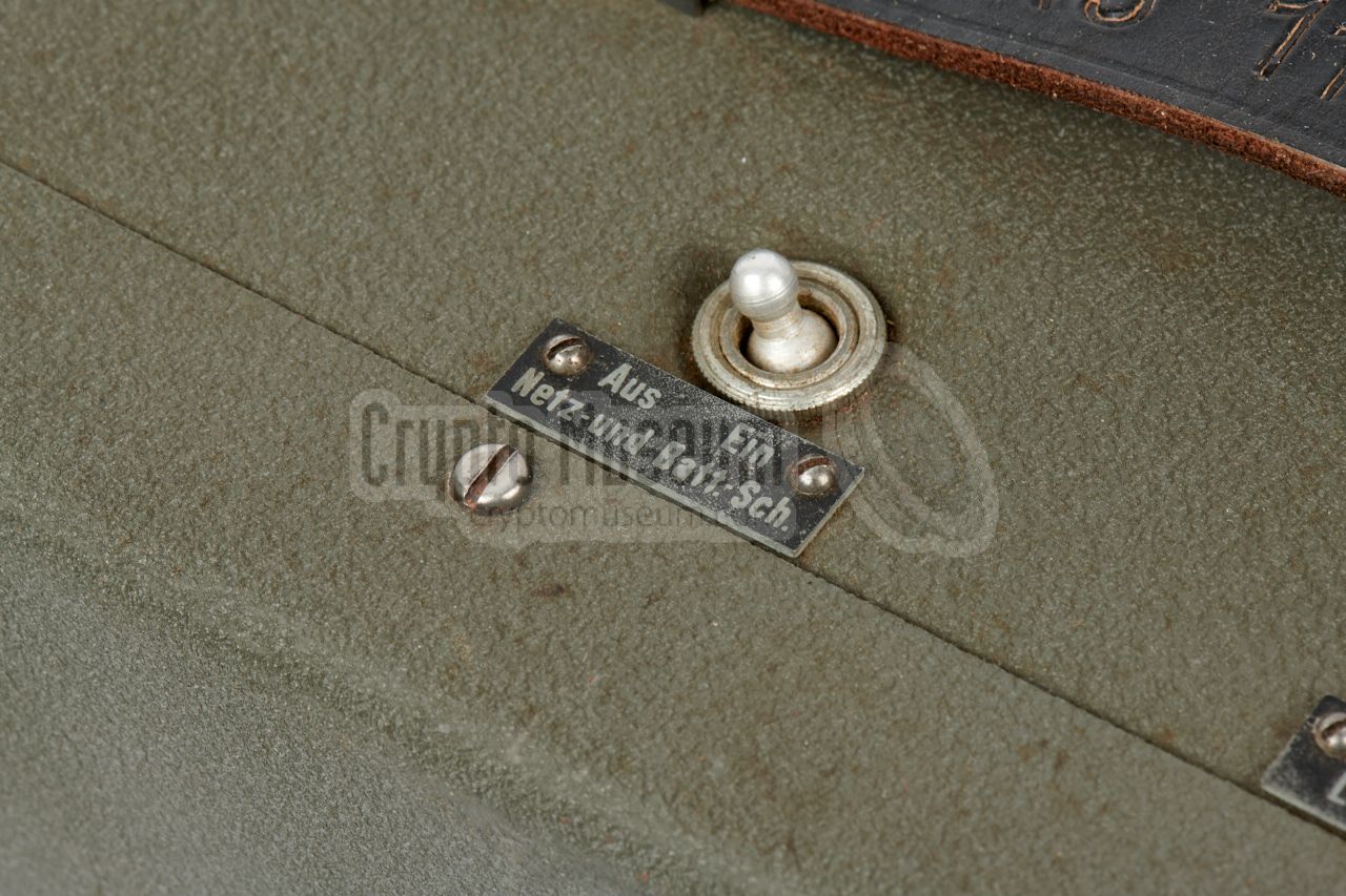
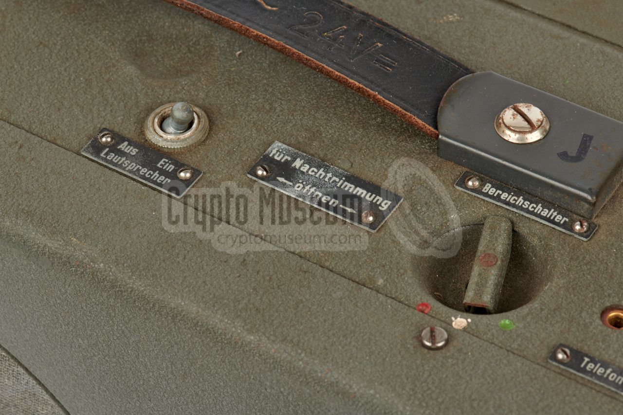
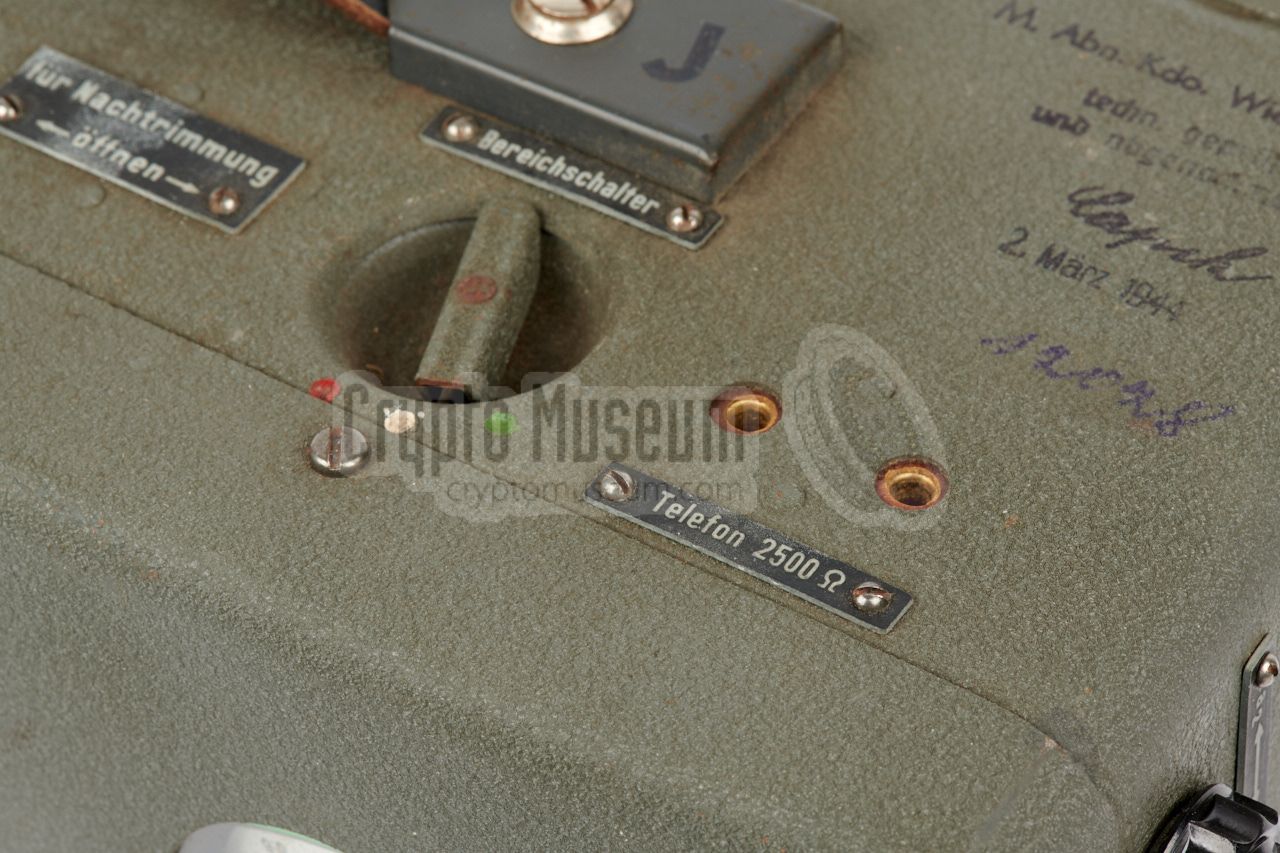
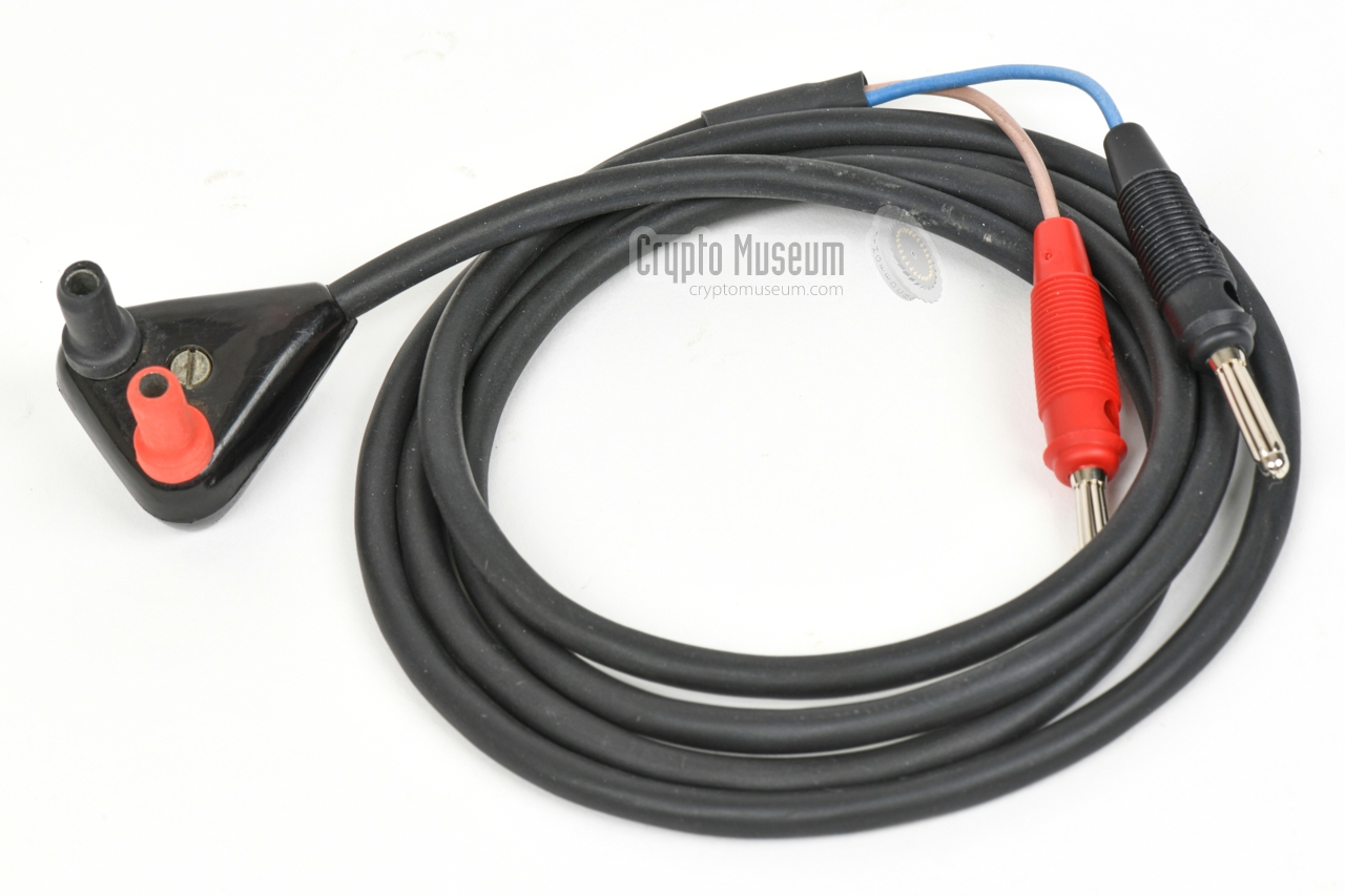
By default, the demodulated audio signal can be heard through
the large internal speaker that is located at the left half of
the front panel.
Alternatively, a
pair of 2500 Ω headphones
– such as the
Wehrmacht headphones shown in the image on the right –
can be connected
to the socket
at the right of the top surface.
When doing this, the internal speaker can be switched
off with a toggle switch at the top.
The Germany Navy usually had its own
type of headphones.
|
|
|
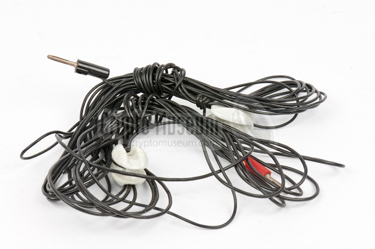
At the
bottom of the right side of the radio,
are two sockets for connection
of the antenna and a suitable counterpoise.
The socket for connection of the antenna is recessed.
The image on the right shows the two antenna wires that came
with the radio. Each wire as a banana plug at one end.
|
|
|
|
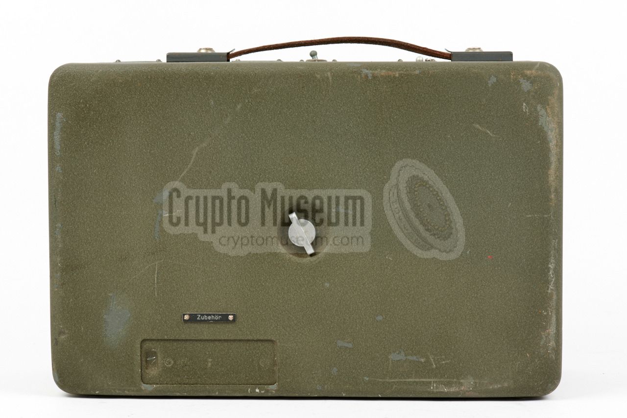
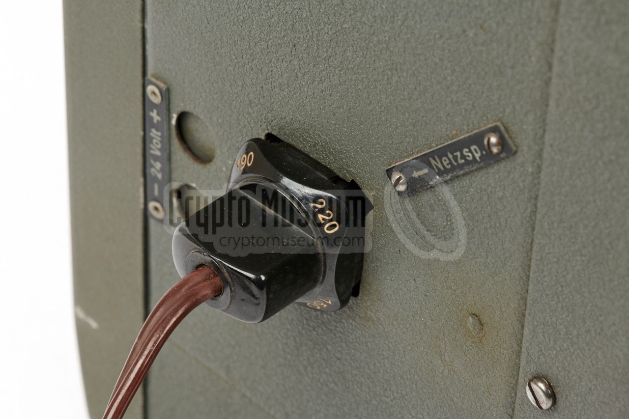
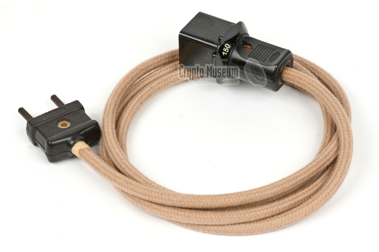
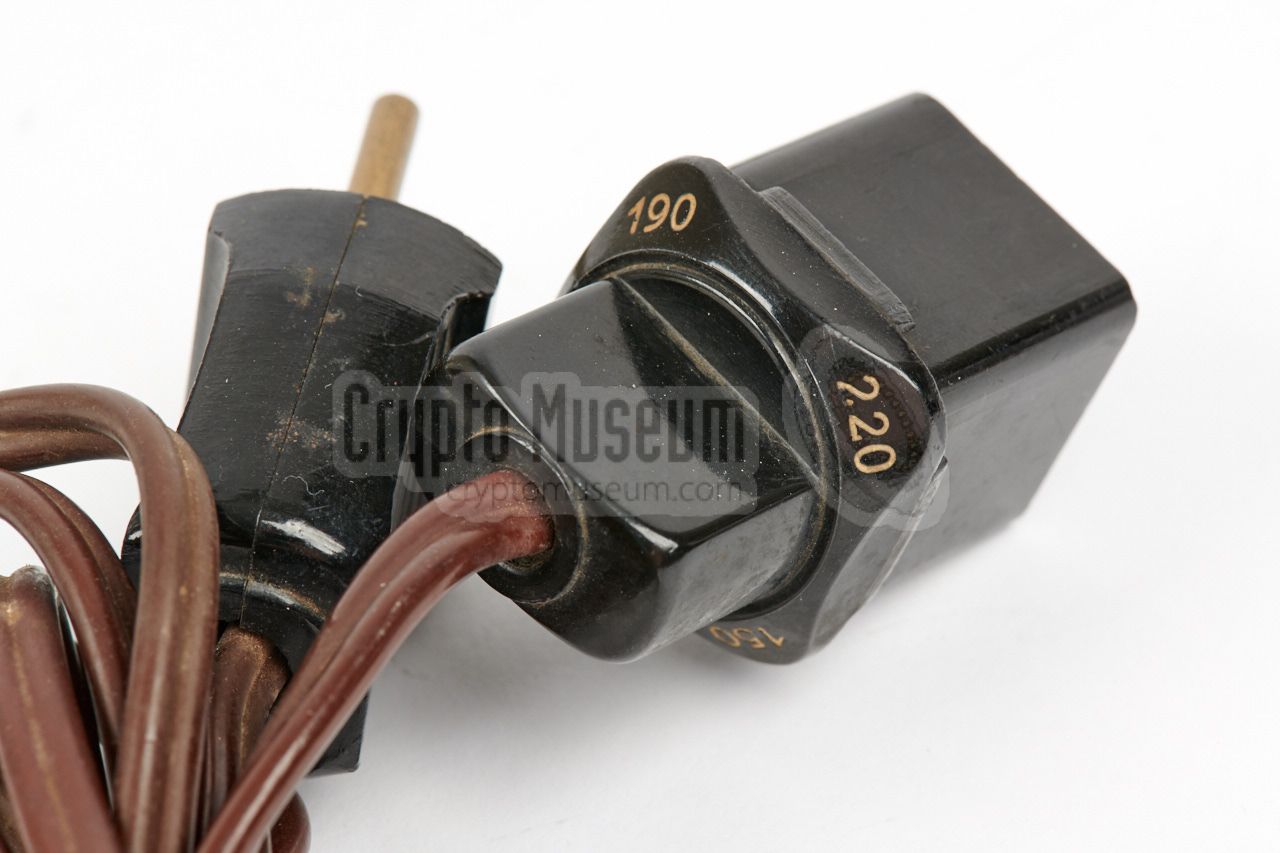
The Radione R3 can be powered from the AC mains by means of the
special power cable that is shown in the image on the right.
The square plug can be
entered in four different ways into the
power socket at the side, with an arrow indicating the selected
voltage.
|
|
|
|
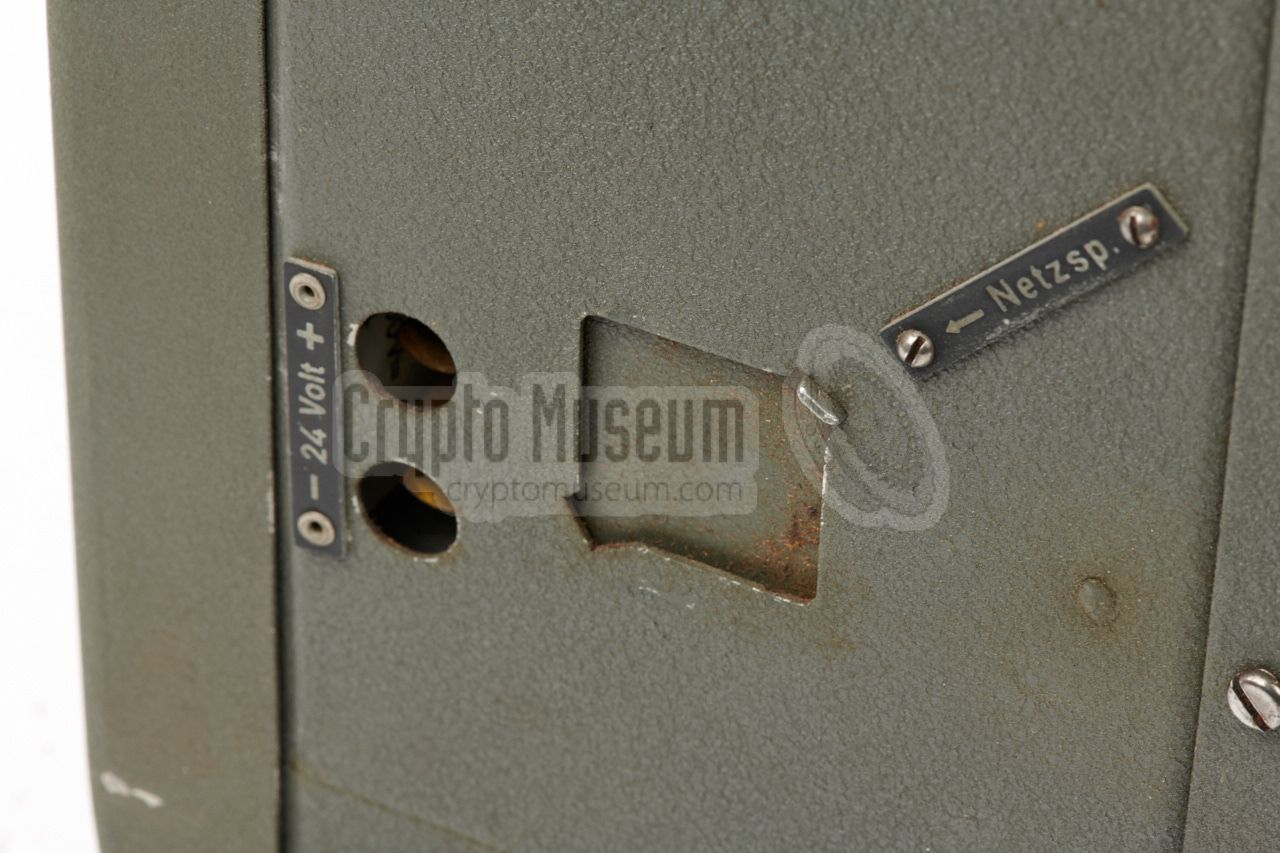
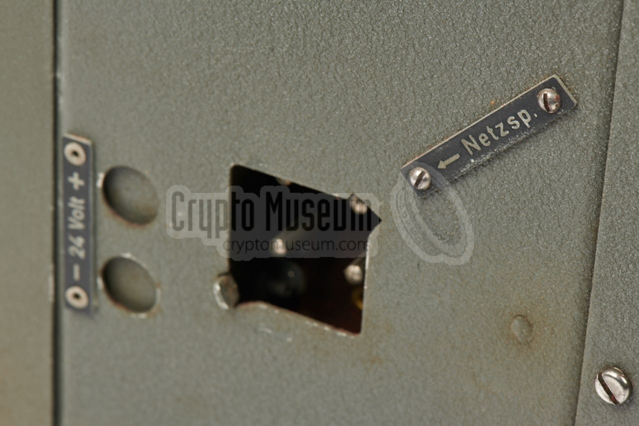
Depending on the version, the radio could also be powered by
a 6V, 12V or 24V DC power source, such as the battery of a car
or boat. The radio featured on this page, is suitable for 24V.
|
|
|
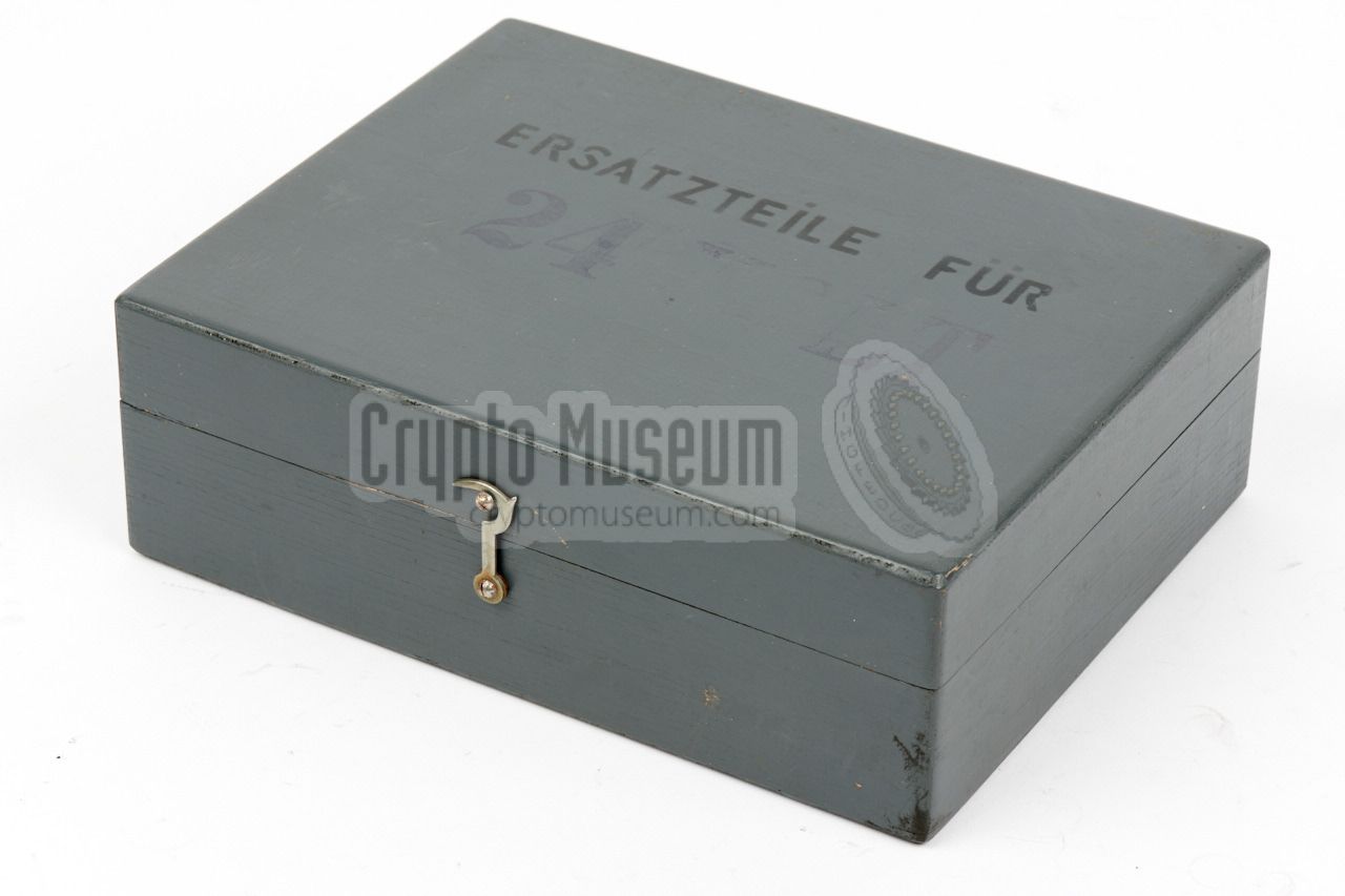
Each R3 receiver can be with a small grey wooden box with spare
parts. The box measures 217 x 72 x 169 mm and contains spare fuses,
spare valves and a spare vibrator.
The image on the right shows the opened box, from which four valves
are currently missing.
|
|
|
Each radio came with a manual that contained operating instructions,
a description of the circuit, and full circuit diagrams for each of
the voltage variants. The March 1942 manual is available for download
below.
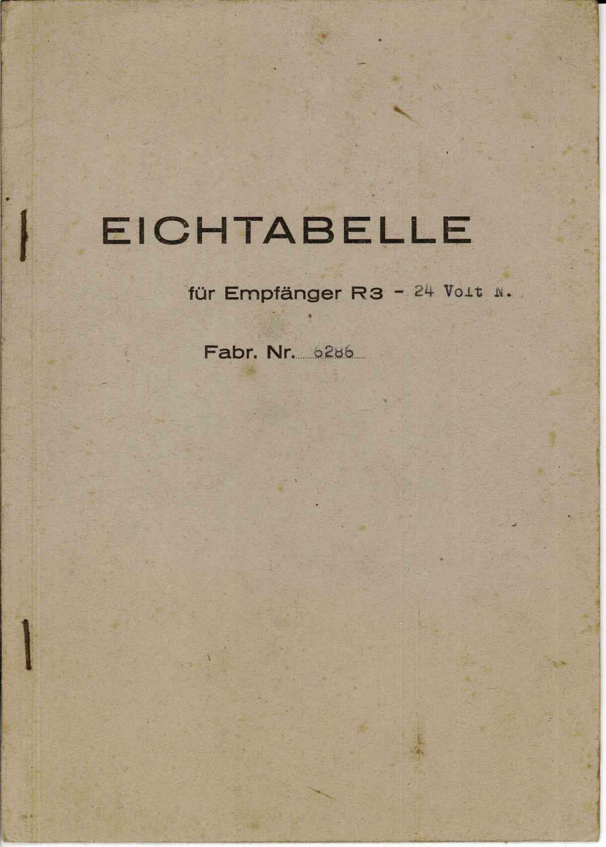
Furthermore, a calibration table
(German: Eichtabelle) was supplied with each radio.
No original available
➤ Download the manual
|
|
|
Below is the block diagram of the R3 receiver. The circuit is built around
six valves that are shown in blue in the diagram. At the left is the EF11
RF pre-amplifier. It delivers its signal to the ECH11, which is a combined
mixer and oscillator. The oscillator is tuned in tandem with the filter
circuits of the RF amplifier and the mixer. The output of the mixer is fed
to the IF amplifier (EF12) which passes it on to the detector
(EBC11), in each case preceeded by a fixed double IF bandpass filter.
For reception of CW signals (morse code), the signal of a
Beat Frequency Oscillator (BFO) can be injected into the detector.
It is built around an EBC11 and can be switched ON when required.
The output of the detector is fed to the audio amplifier, which is
built around an EDD11 double triode in push-pull configuration. It has
a transformer-based output circuit which drives the speaker.
|
|
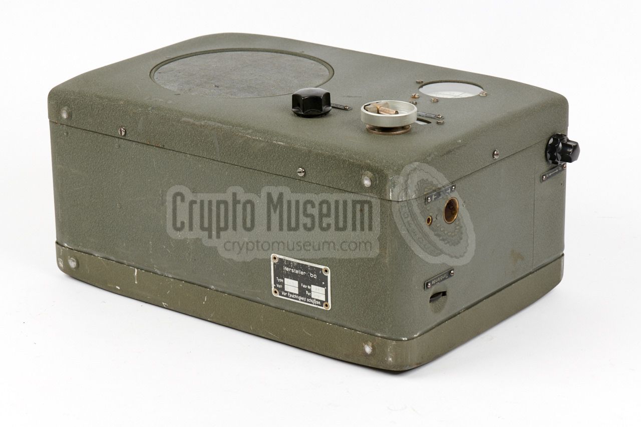
The R3 is housed inside an aluminium enclosure that is covered
in green/grey wrinkle paint.
The interior can be accessed easily from the rear,
by removing the large bolt at the centre of the rear panel
and (carefully) taking the rear panel off. Note that the
rear panel may be binding somewhat.
|
The image on the right shows the interior of the R3, as seen from
the rear left, after the rear panel has been removed. Inside the
case is a metal frame that holds the larger parts, such as the
valves, the filters and the mains transformer.
The image above shows the position of each of the seven (black) valves.
Note that the type of each valve is printed on the metal chassis,
aside each valve socket. The large rectangular part at the left
is the tuning capacitor that consists of three individual capacitors
that are operated in tandem. It is controlled from the front panel.
|
|
|
|
The six shiny square parts are the filters that are situated
at the antenna input and between the various stages of the radio.
Some of these filters are adjustable. At the bottom right is a
fairly heavy mains transformer that is suitable for the most
common AC mains voltages in the world.
|
The radio can also be powered by an external DC power source,
such as the battery of a car or truck. Depending on the version,
it is suitable for 6V, 12V or 24V DC. The version shown here was
made for 24V, which should be connected to the (+) and (-)
terminals at the side of the radio.
At the top right is the 24V vibrator pack. It is housed in an
cylindrical aluminium enclosure, and converts the DC input
into an alternating current (AC) that feeds the mains transformer.
The transformer then provides the necessary HT voltages for the
valves and for the filaments (LT).
|
|
|
|
The passive components (resistors, capacitors, coils, etc.) are
located at the other side of the frame and can only be accessed
by removing the front panel. For this it is necessary to remove
the knobs from the front panel, plus the six screws around the
edges of the front panel.
|
|
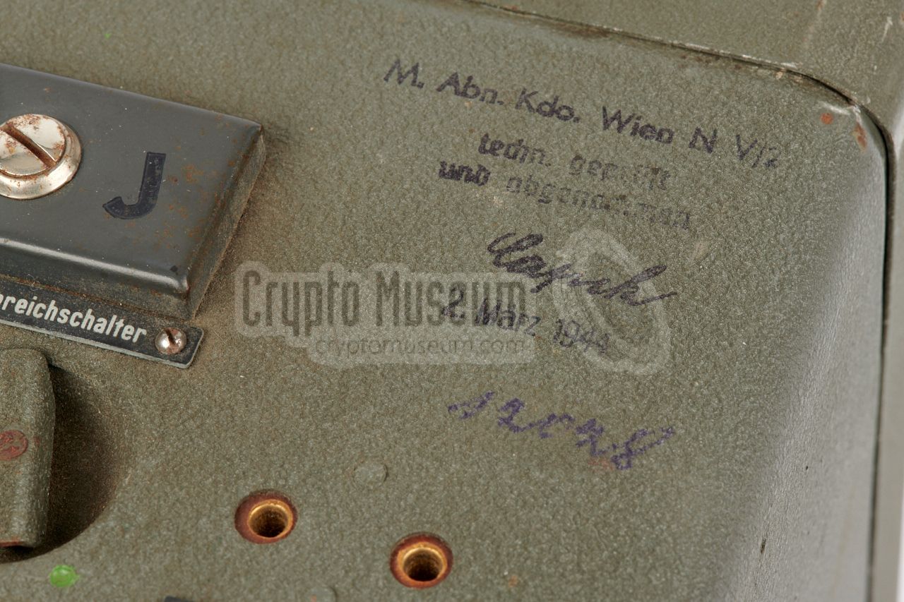
According to the acceptance stamp on the top right of the body,
the R3 receiver featured on this page was delivered to the German
Navy in Wien (Vienna, Austria) on 2 March 1944. At the end of the
war it was stored in an attic with the message that it would soon
be picked up by someone else. That person never came however and
after the few years, the mysterious box was forgotten.
|
The radio was stored in its original grey wooden transport case, but the
person who kept it had no idea what was actually inside the box.
Many years later, the mysterious case resurfaced and the keeper finally
wanted to know what it was hiding. As the lock at the top was locked
and could not be opened easily,
it was decided to break the two hinges at the bottom of the lid.
Out came a Radione R3 that appeared to be in very good condition.
Although the metal rigs at the corners of the case had become rusty,
the case had apparently preserved its contents well.
|
|
|
- Wooden transport case cleaned outside and inside.
- Radio exterior cleaned.
- Front panel paint scuff marks restored.
|
Frequency 2.5 - 25.7 MHz Bands 3 (see below) Sensitivity 5 - 10 µV (AM), 1 - 2 µV (CW) AF amplifier Class B push-pull Output 2500 Ω Mains 120, 150, 190 or 220V AC Battery 6, 12 or 24V DC (external) Consumption 30 Watts Dimensions 350 x 240 x 175 mm Weight 11 kg
|
EF13 HF amplifier ECH11 Mixer EF12 IF amplifier EBC11 Detector/driver EBC11 BFO EDD11 AF amplifier EZ11 Rectifier (for anode voltage)
|
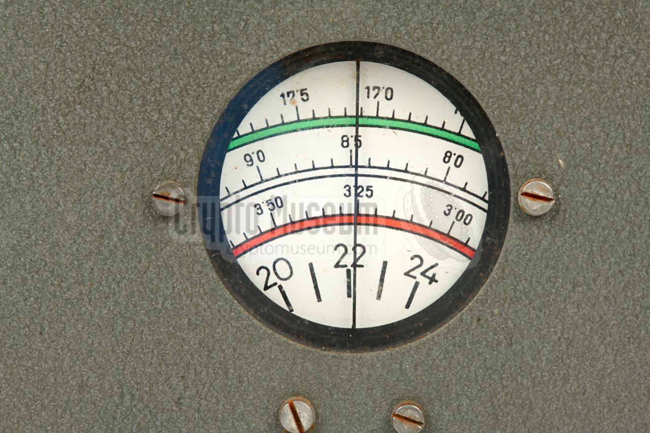
Red ● 2.5 - 6.7 MHz White ● 6.7 - 14.8 MHz Green ● 14.8 - 25.7 MHz
|
|
We are currently looking for the following items:
|
Original manual - 24V DC cable
- Additional spare valves
- Photographs about the use of the R3
|
|
|
|
Any links shown in red are currently unavailable.
If you like the information on this website, why not make a donation?
© Crypto Museum. Created: Wednesday 22 March 2017. Last changed: Wednesday, 05 November 2025 - 12:10 CET.
|
 |

|
|
|


![Example of a Radione R3 and RS-20M being used in a German Wehrmacht bunker. Image via [3].](img/r3_bunker_large.jpg)


![Headphones used by the Kriegsmarine [5]](img/phones_km_thumb.jpg "image # phones_km_large.jpg")


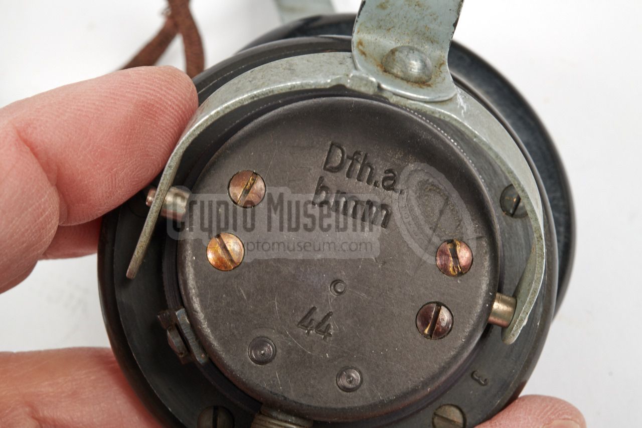


![Headphones used by the Kriegsmarine [5]](img/phones_km_large.jpg)