|
|
|
|
|

|
|
Germany WWII Abwehr Radione R-3 →
The device is housed in a steel enclosure, and was built from standard
civil parts. Nevertheless it turned out to be a reliable and service friendly
unit, not least because of the fact that the
valves (tubes) are accessible from the front,
whilst the interior can be accessed easily
from the rear.
The transmitter is crystal controlled and
covers a frequency range from 3 to 14 MHz, divided over
three bands. It produces an output power of 20W in CW, but can
also transmit voice in Amplitude Modulation (AM) with an output power of 12W.
The image on the right shows a typical RS-20/M.
|
|
|
|
The RS-20/M was introduced around 1941 and was initially intended for
use by the Navy (Kriegsmarine), hence the suffix M to the model number.
Although it was possible to connect a microphone,
it was commonly used in CW mode (morse).
The same version was later also used by the Army (Wehrmacht) in CW mode (morse) as well as in AM (phone). A special version (without the suffix 'M')
was made for the Air Force (Luftwaffe).
It has a 4-pin Brechkupplung at the front panel.
According the Radione founder Nikolaus Eltz, several thousands RS-20(M) units
were made [9].
|
-
The letters 'RS' stand for Radione (manufacturer)
Sender (transmitter). The number '20'
indicates the power output of 20W. The suffix 'M' indicates that the unit
was developed for the German Navy (Marine).
|
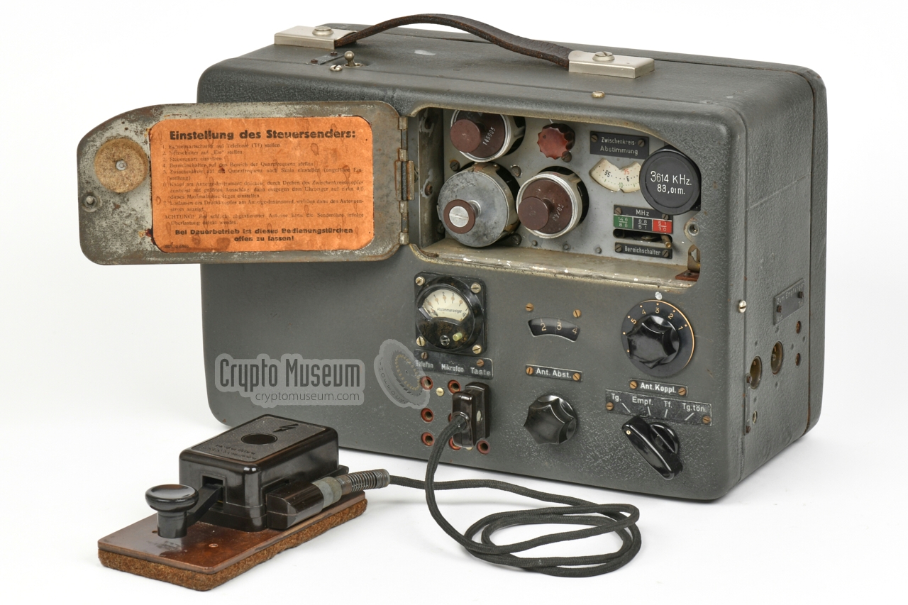
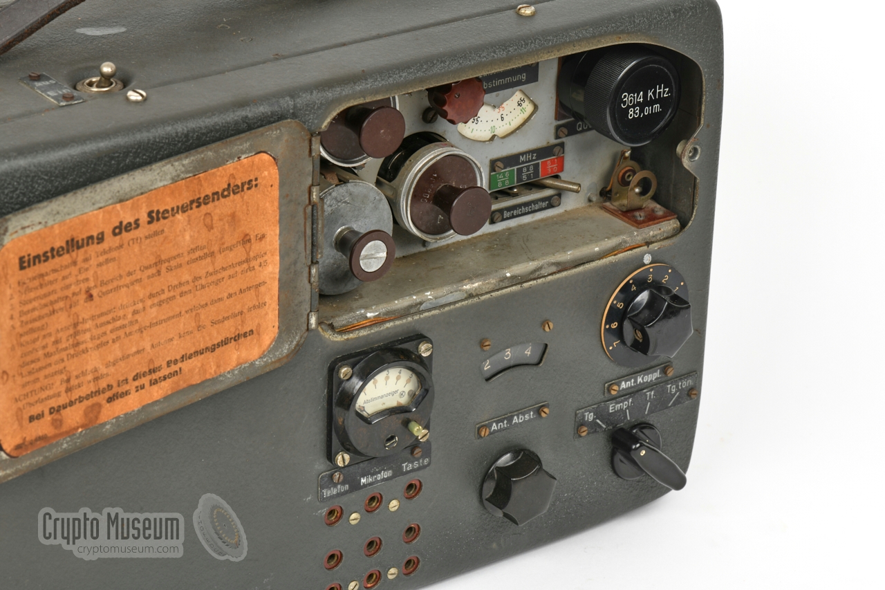
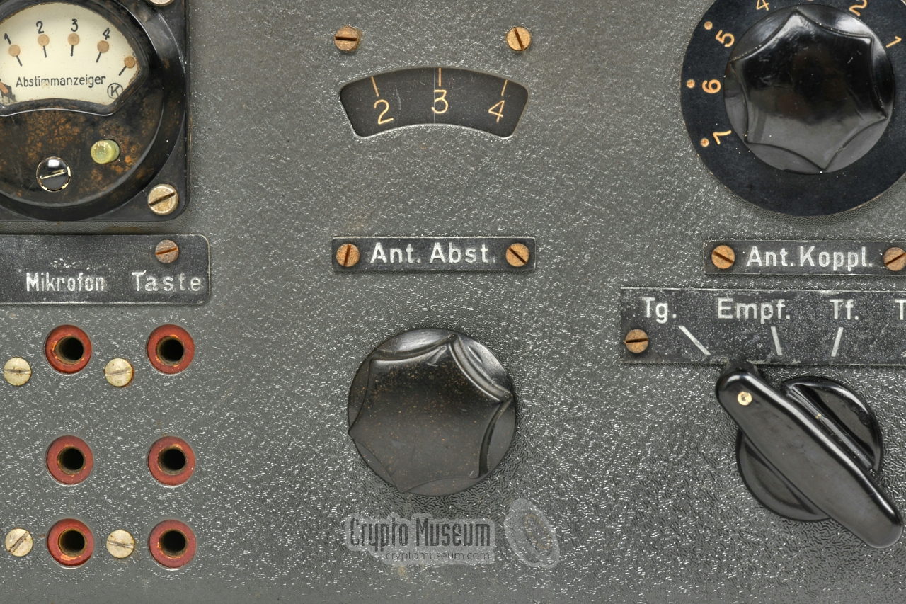
The image below gives an overview of the controls and connections of the
transmitter. At the left side
are the sockets for connections of the AC
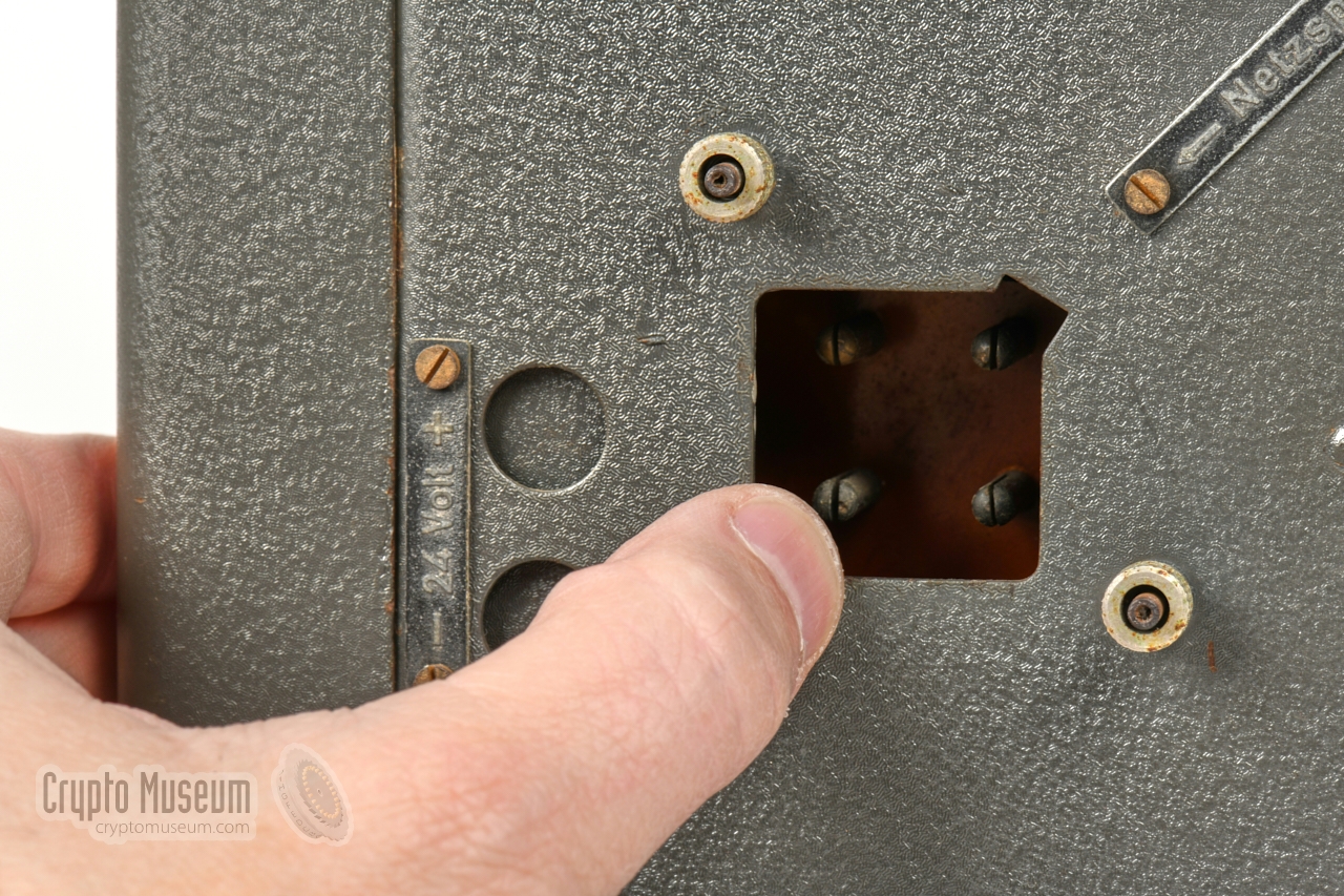
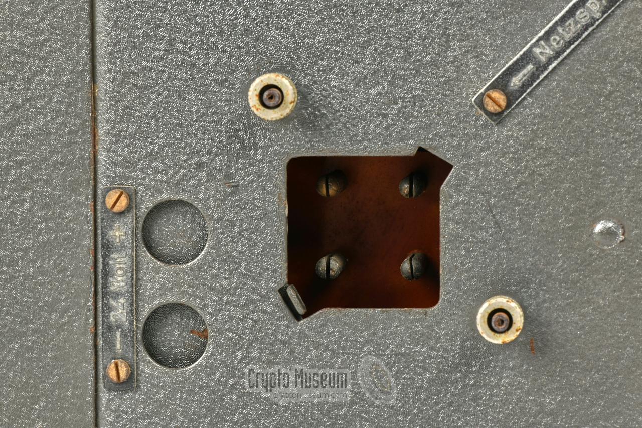
mains and for 24V DC. A pivoting flap
ensures that only one of the two power
sources can be used. This flap also controls the
internal AC/DC switch.
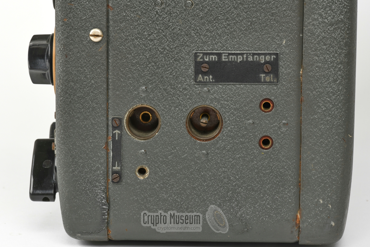
At the right side are the sockets for connection of
the antenna and counterpoise,
plus the sockets for connecting
the matching Radione R-3 receiver, which is then controlled
from the transmitter.
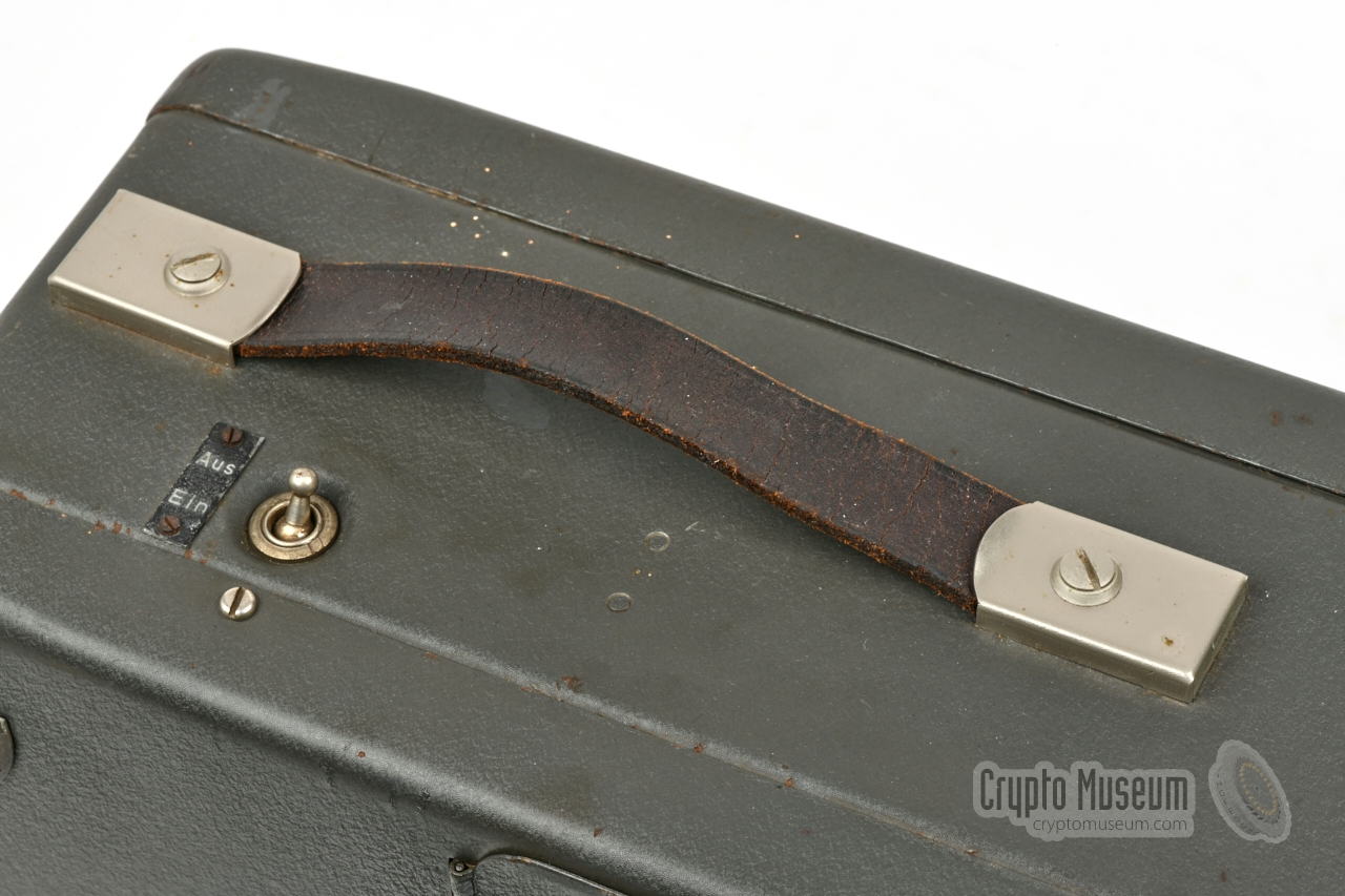
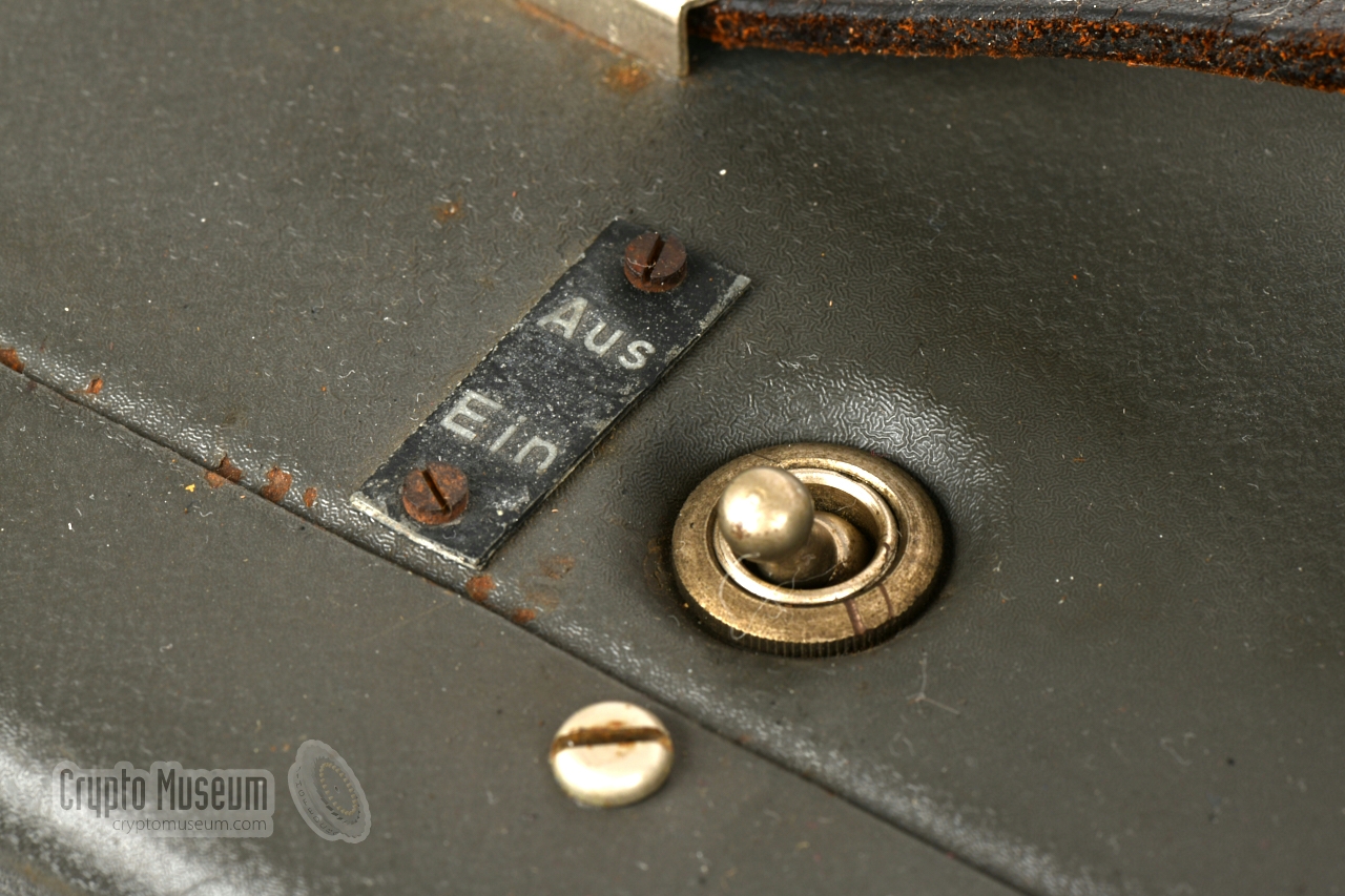
The unit is turned ON with the power switch
on top of the device.
The desired mode of operation should then be selected with the
MODE selector at the bottom right.
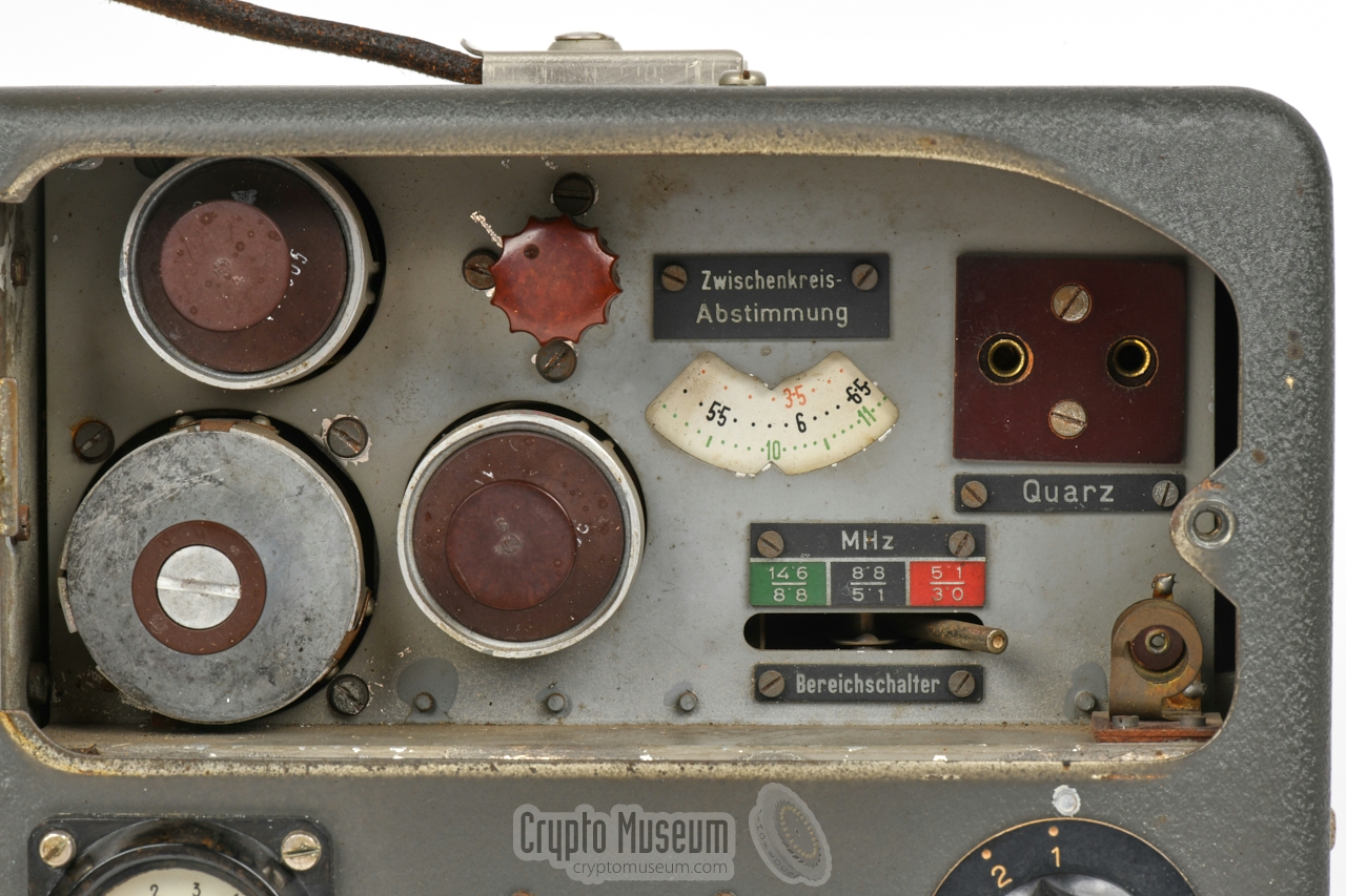
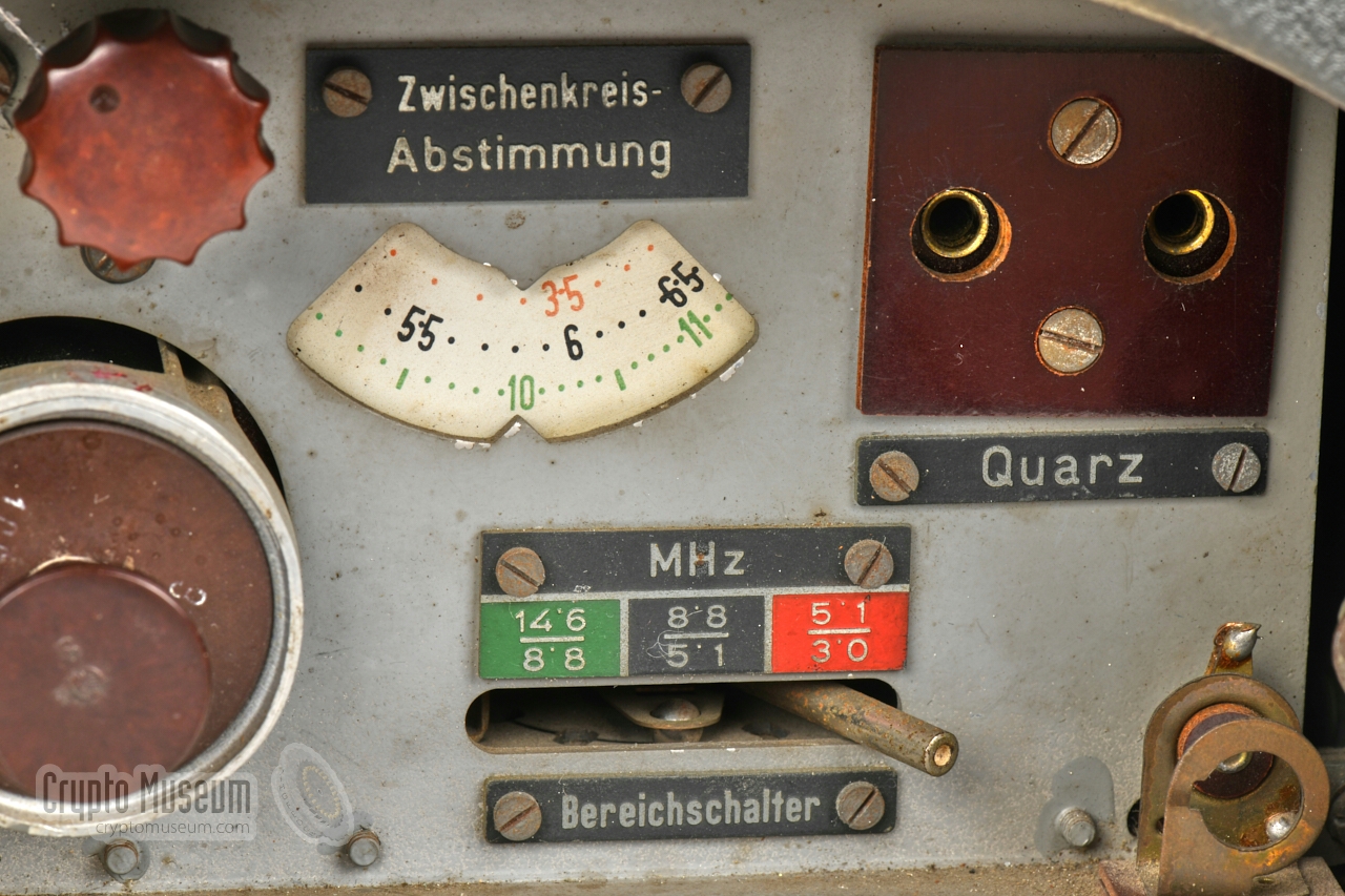
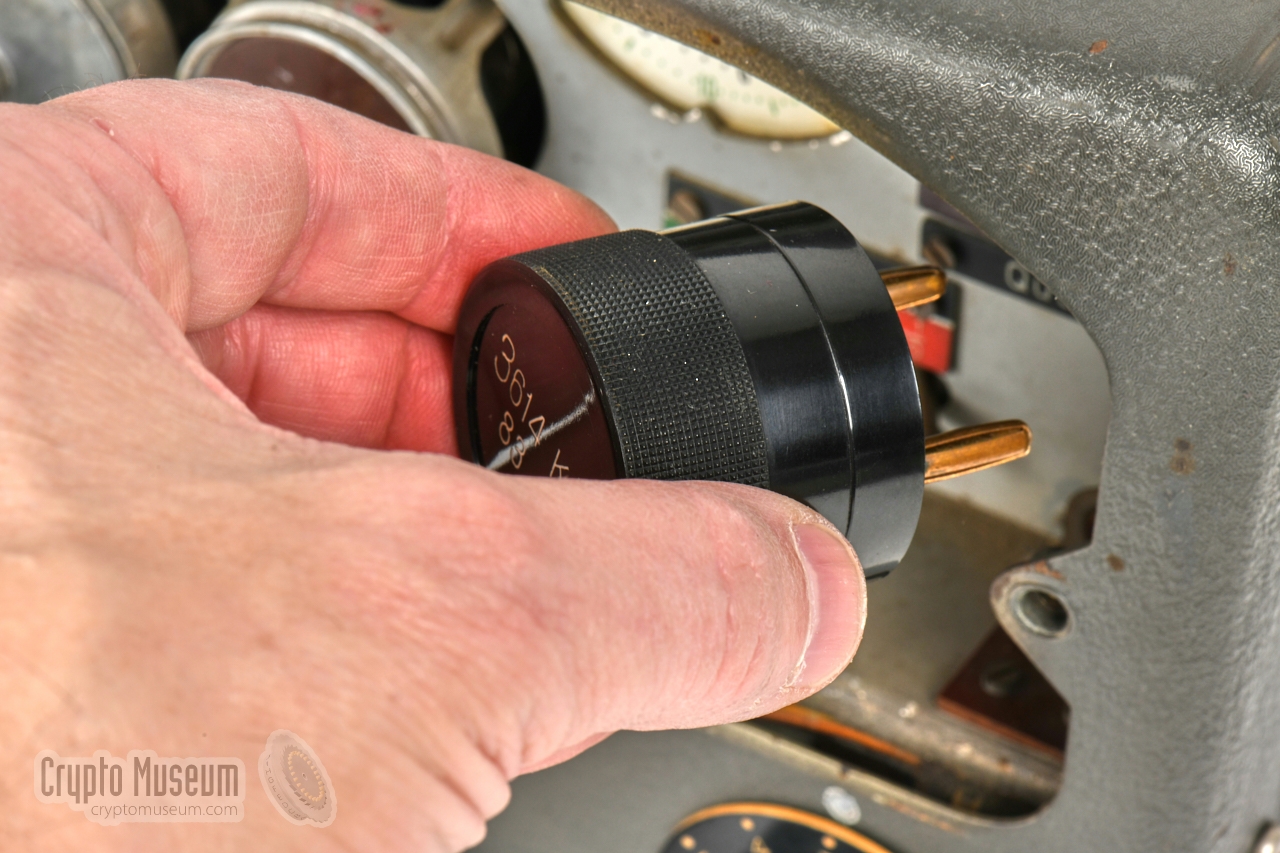
A crystal should be installed in the
socket at the top right,
behind the hinged door. This section also holds the
band selector, the oscillator tuning and the valve sockets.
The door has a felt pad to keep the crystal in place.
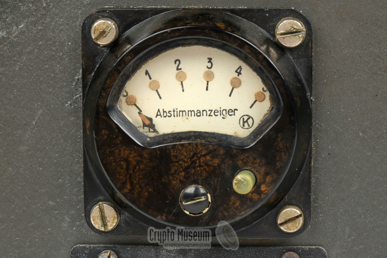
When tuning the
device for maximum power output, the antenna range selector should be used
in combination with the antenna tuning knob (Ant. Abst.),
using the meter to find the optimum.
As long as the small button on the meter is depressed, the meter
shows the oscillator output level.
At the bottom centre are the sockets for connection of headphones,
microphone and morse key.
|
Tg. Morse code (A1) RX Empf. Reception (looped to R-3 receiver) AM Tf. Amplitude Modulation (A3, voice, phone) Tg.tön. Modulated morse code (A2, tone morse code)
|
- RS-20/M
This is the standard version of the Radione 20W transmitter. It was initially
developed for the Navy (Kriegsmarine) – suffix M – but was also
used by other parts of the German war machine. Most of the surviving
units, including the one featured here, are of this type.
- RS-20
This version was made especially for the
German Air Foirce (Luftwaffe).
It does not have the suffix M on the model plate, and can be recognised
by the presence of a 4-pin Brechkupplung (break coupling) at the
front panel. This version is extremely rare.
|
|
The Radione RS-20M was a universal semi-portable shortwave transmitter that
was suitable for a wide variety of applications. Below are some examples of
its users:
|
- Kriegsmarine
The R-3
and the RS-20M were used by the German Navy (Kriegsmarine)
as the standard radio set aboard some of its smaller vessels.
- U-Boat
The Radione R3 receiver and RS-20/M transmitter were also used by the
U-Boat division of the Kriegsmarine — mainly for backup purposes —
and for troops that were landed ashore for special operations (commandos).
➤ Trivia: The R-3 receiver is visible in the movie Das Boot
➤ Wikipedia.
- Wehrmacht
During WWII, the German Army (Wehrmacht) used the Radione R3 receiver
and the RS-20/M transmitter for mobile installations, for example in
bunkers (see below).
- Luftwaffe
The German Air Force (Luftwaffe) used a special variant
of the RS-20
(not RS-20/M) that has a so-called Brechkupplung (break coupling)
at the front panel – instead of the three 3-pin sockets – for connection
of a headset. It was used in AM mode (A3, voice).
- Abwehr
The German Intelligence Service, the Abwehr,
used the R-3/RS-20M as a small commando station [2].
The R-3 was also used as a stationary receiver in some head-end stations
of the Abwehr, commonly in combination
with an existing transmitter like the S-87/20
[3].
- Sicherheitsdienst (SD)
Another WWII German secret service, the Sicherheitsdienst or SD
(security service), also used the Radione R3. Examples are
secret agent Richard Kauder (codename: Klatt), who used it in Sofia (Bulgaria),
and Franz Mayr, who used it in Tehran (Persia, now: Iran) [5].
|
It is often thought that the Radione Radio Set was only used by the German
Navy (Kriegsmarine), but the image below — taken in a wartime bunker —
shows that it was also used by the German Army (Wehrmacht). At the far
right is the Radione RS-20M transmitter, which is used here in AM mode
(phone). To its left is the Radione R3. At the far left is a
DR-78 transceiver made by Philips.
According to Norwegian collector Jørgen Fastner, it is also possible that
this picture was taken in a Coastal Artillery bunker, in which case
it has to be attributed to the Navy (Kriegsmarine) [7].
|
|
It is little known that the RS-20 transmitter and the R-3 receiver
were also used by the German Air Force
(Luftwaffe), most likely for use in air raids, in airplanes that
did not have a standard radio fitted. Note that the model number
of the Luftwaffe version does not have the suffix M.
|
Furthermore
it has a so-called Brechkupplung (break coupling) at the front panel
instead of the 3-pin sockets of the Naval RS-20/M.
This was the regular connection that was used in the cockpit of the German airplanes at the time.
Note that the Luftwaffe used the transmitter primarily
in AM (A3, voice) mode, for which an external headset with
microphone and speakers is required.
The image on the right shows one of the few surviving units of this type [7].
Better quality images will be provided as and when they become available.
|
|
|
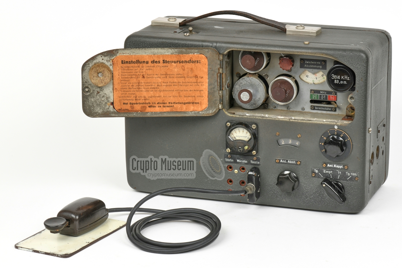
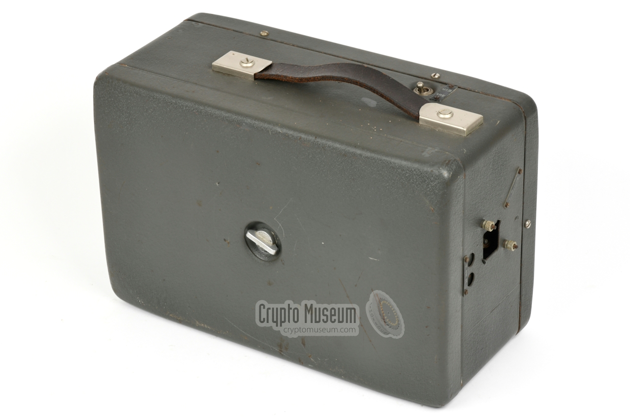
The image on the right shows the common RS-20/M version of the transmitter,
which is housed in the same metal enclosure as the matching R-3 receiver.
It was the standard enclosure that Radione used for its civil receivers
at the time.
It has a hinged panel behind which the valves (tubes) and the
quartz crystal can be accessed directly.
At the front panel are three 3-pin sockets for connection of a pair of
headphones, a carbon microphone and a morse key.
|
|
|
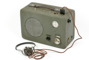
Although the RS-20 transmitter can be used in combination with virtually
any short wave (SW) receiver, it was commonly supplied wih the Radione R-3
shown in the image on the right.
The R-3 is basically a military variant of the civil R-2, but has an improved
frequency dial with a smooth fine-tuning gear. It can be used stand-alone,
but may also be operated via the RS-20/M transmitter, by means of a
special cable set.
➤ More information
|
|
|
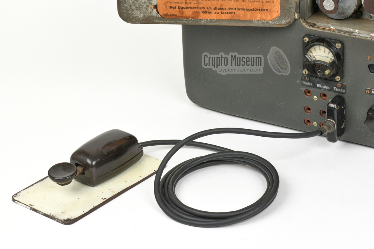
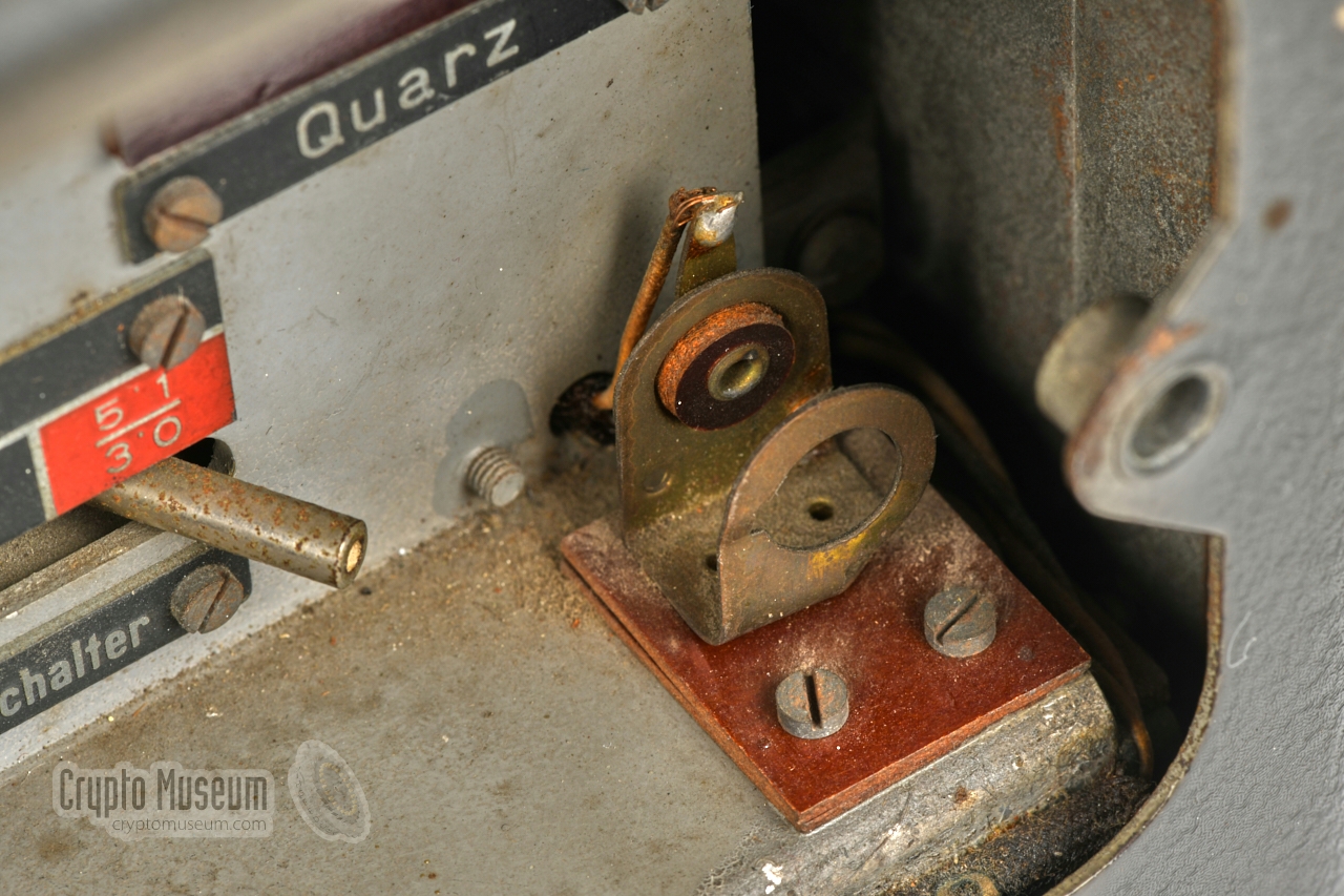
Depending on the end-user, the RS-20 was supplied with one of the following
morse keys: the Navy (Kriegsmarine) used it with a standard
Junker key in its
U-boats, whereas the Army (Wehrmacht) used the common
Wehrmacht key.
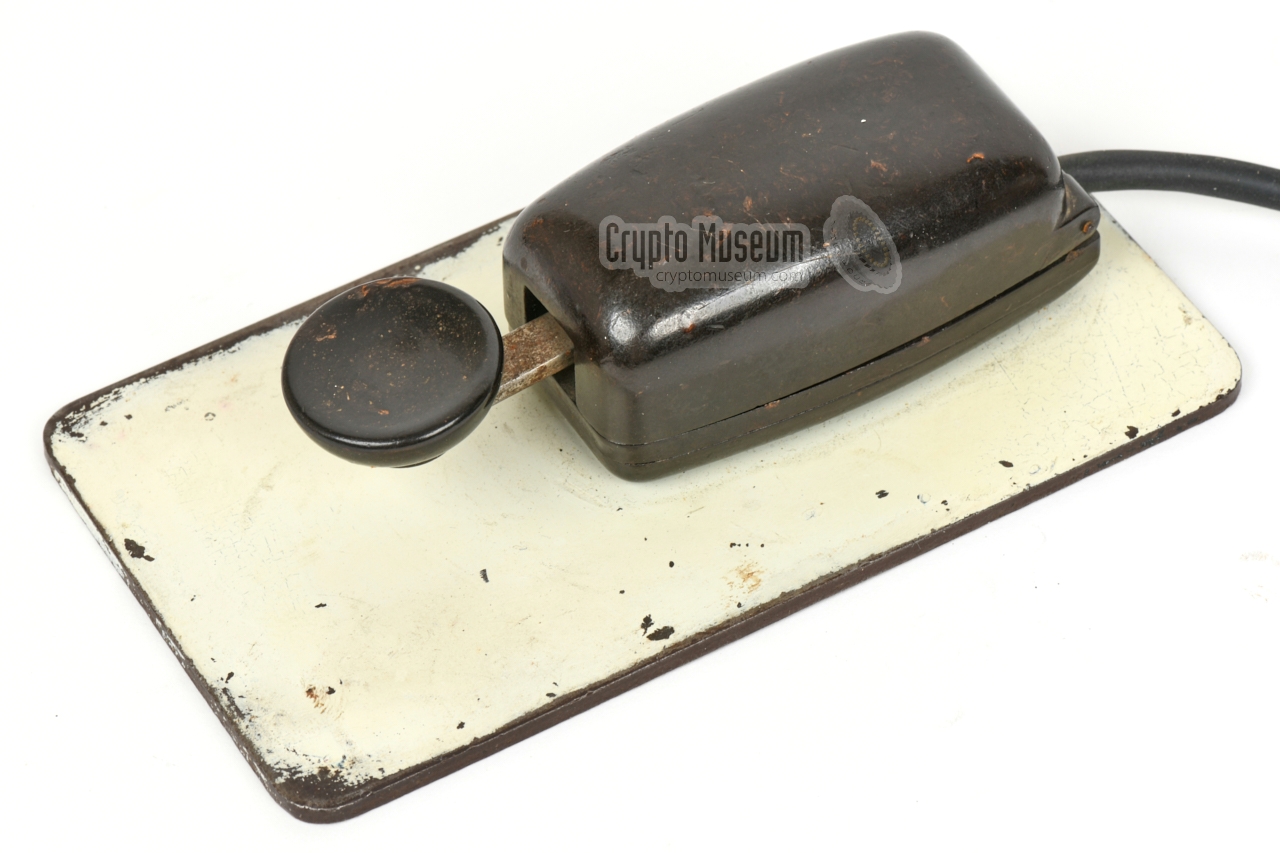
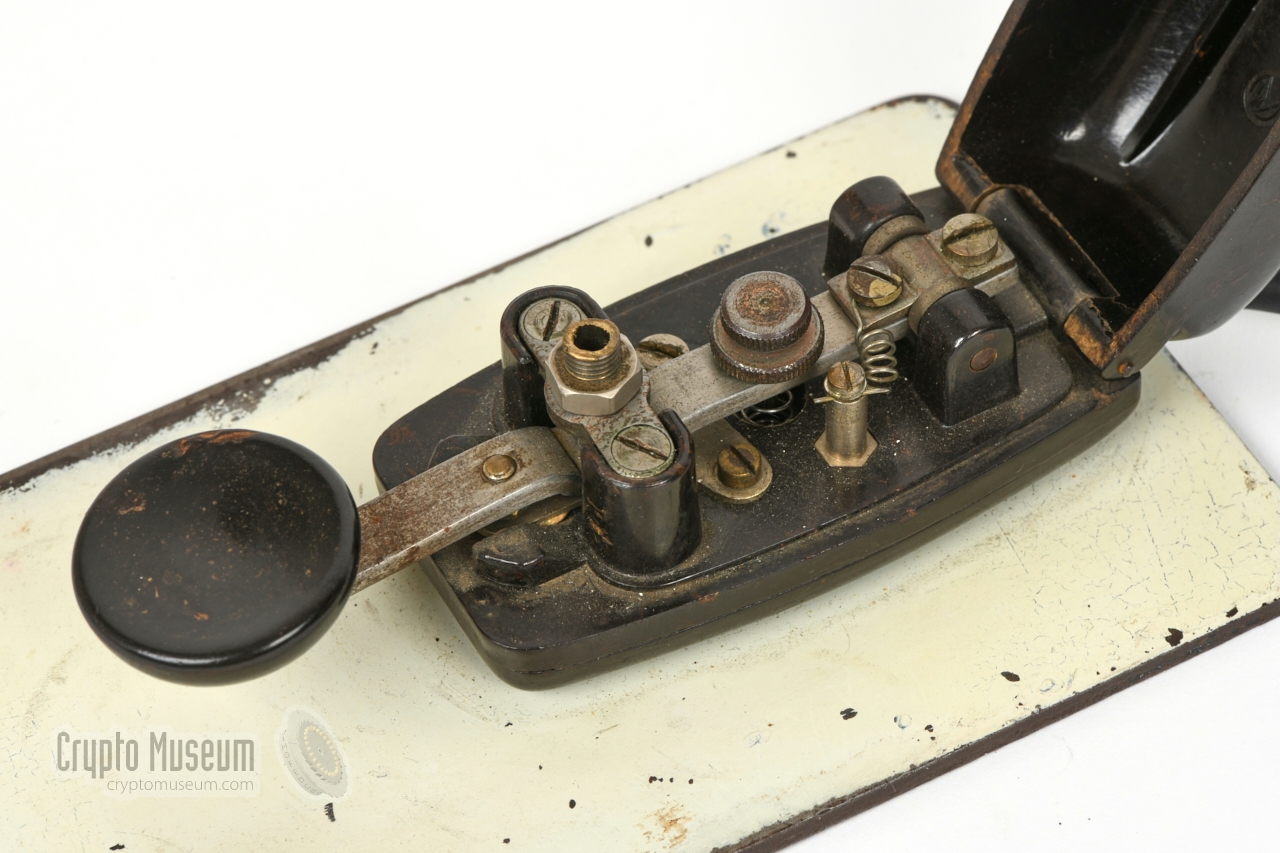
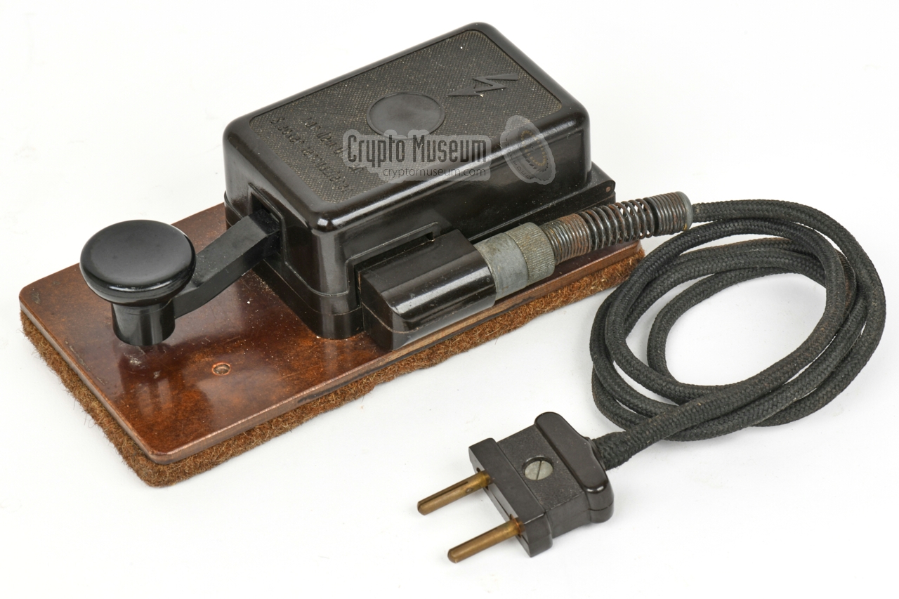
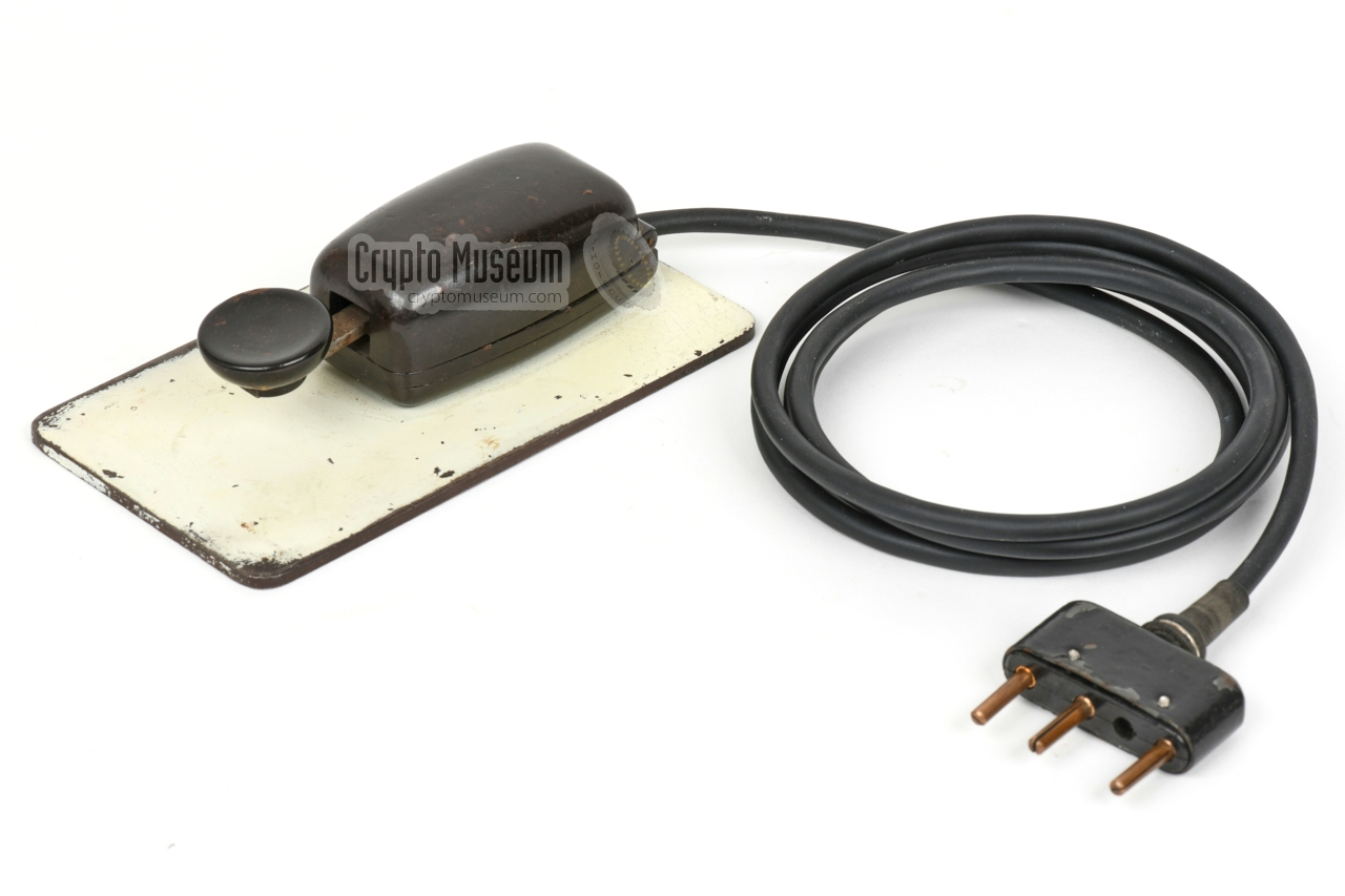
The German intelligence service – Abwehr
– used a so-called Mouse key mounted on a metal
base plate, as shown in the image on the right.
In practice however, operators (in many cases also amateur radio
operators) commonly brought their own personal morse key.
|
|
|
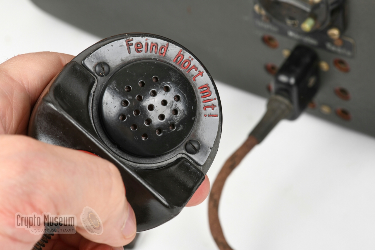
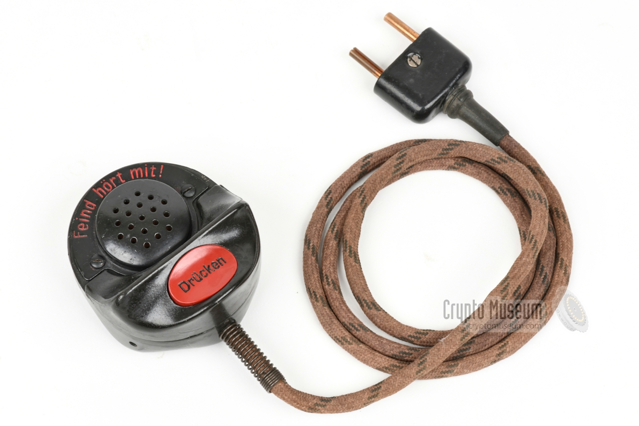
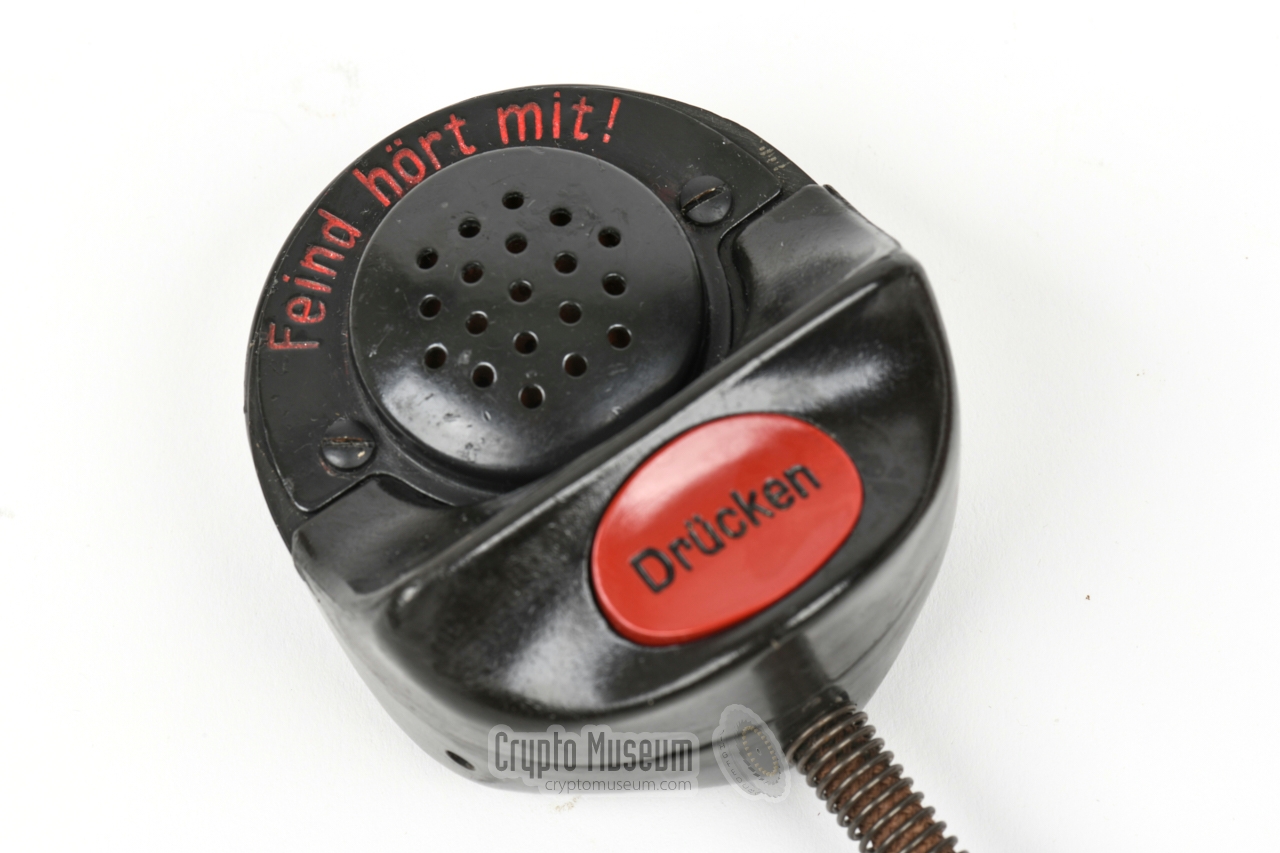
Although the RS-20/M was primarily intended for the transmission of CW
signals (morse), it was also suitable for the transmission of speech by
means of Amplitude Modulation (AM).
For this purpose, the RS-20/M has a 3-pin socket at its front panel, that
accepts a standard Germany Army (Wehrmacht) carbon microphone, such as the
one shown in the image on the right. As the voice communication was not
encrypted, the microphone carries the engraved warning:
Feind hört mit (the enemy is listening).
|
|
|
When using the RS-20 in combination with the Radione R3 receiver,
the headphones output of the receiver should be connected to the audio
input at the right side of the transmitter.
The 2500 Ω headphones of the receiver may then be connected to the
socket marked Telefon at the front panel of the transmitter.
It allows the transmitter to insert a sidetone into the
headphones when transmitting in morse code.
In RX mode, the audio from the receiver is passed.
|
|
|
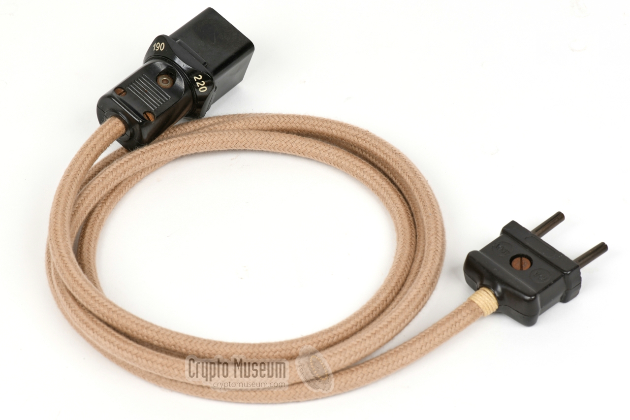
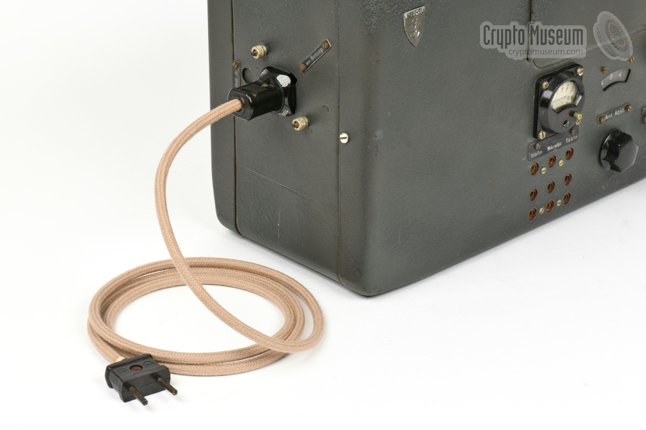
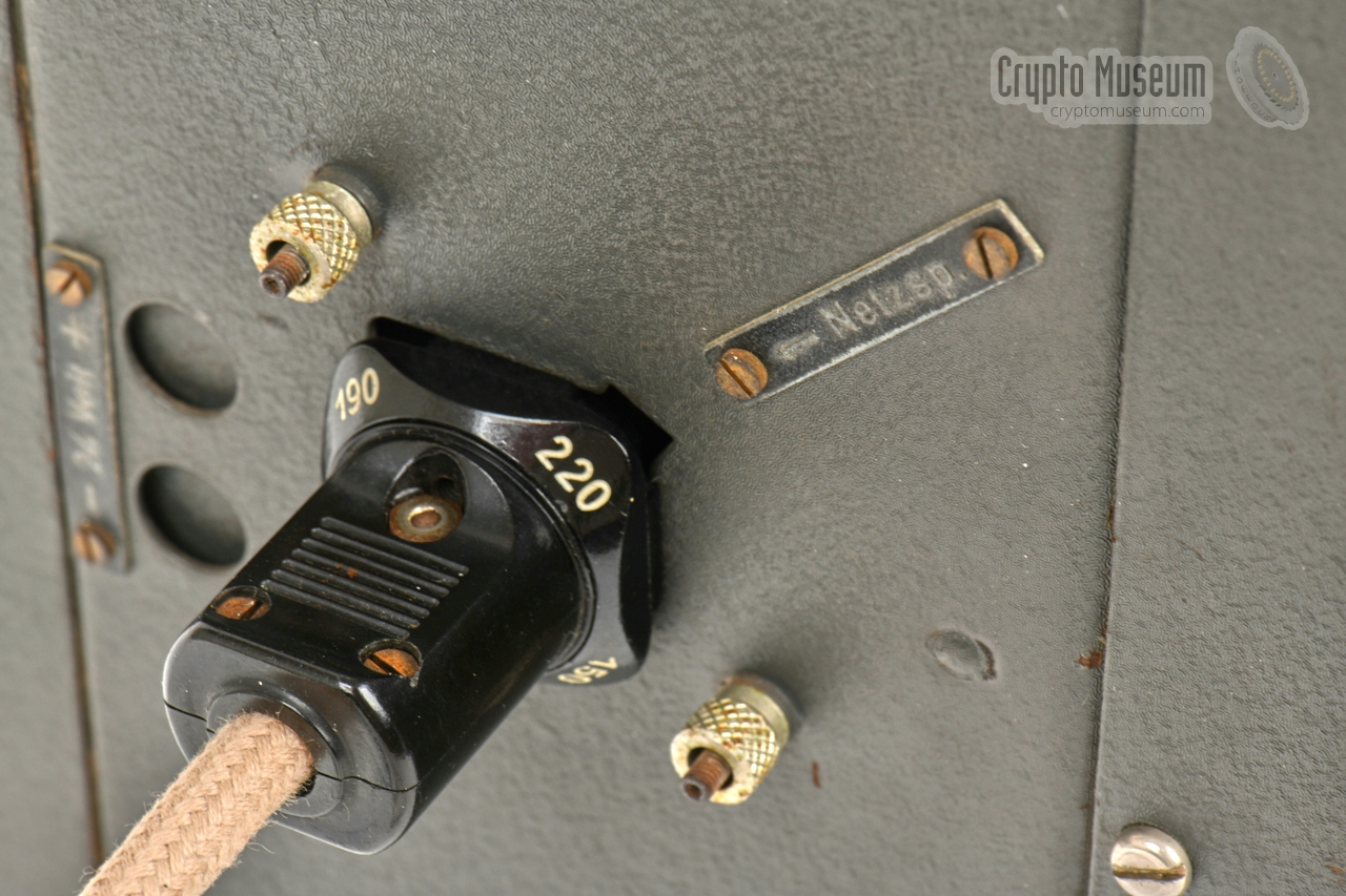
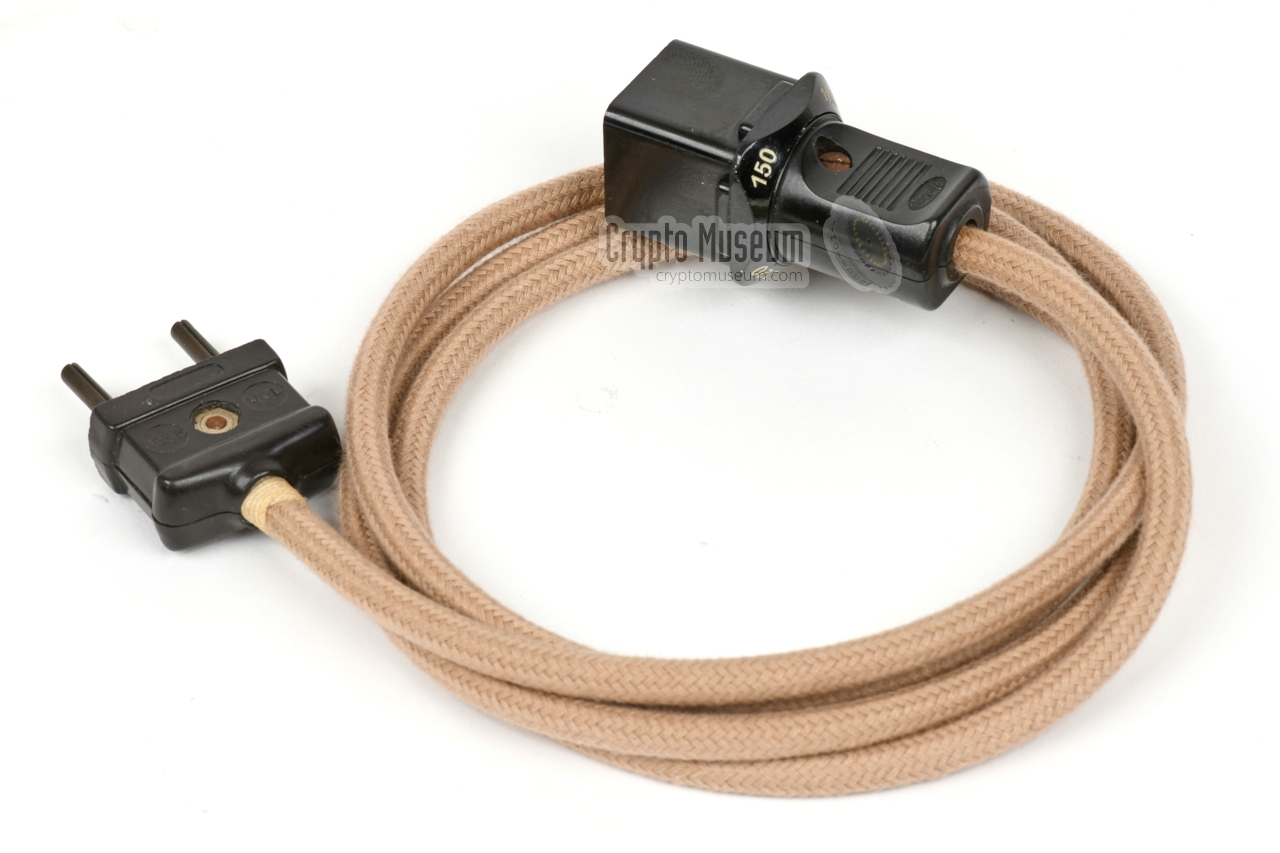
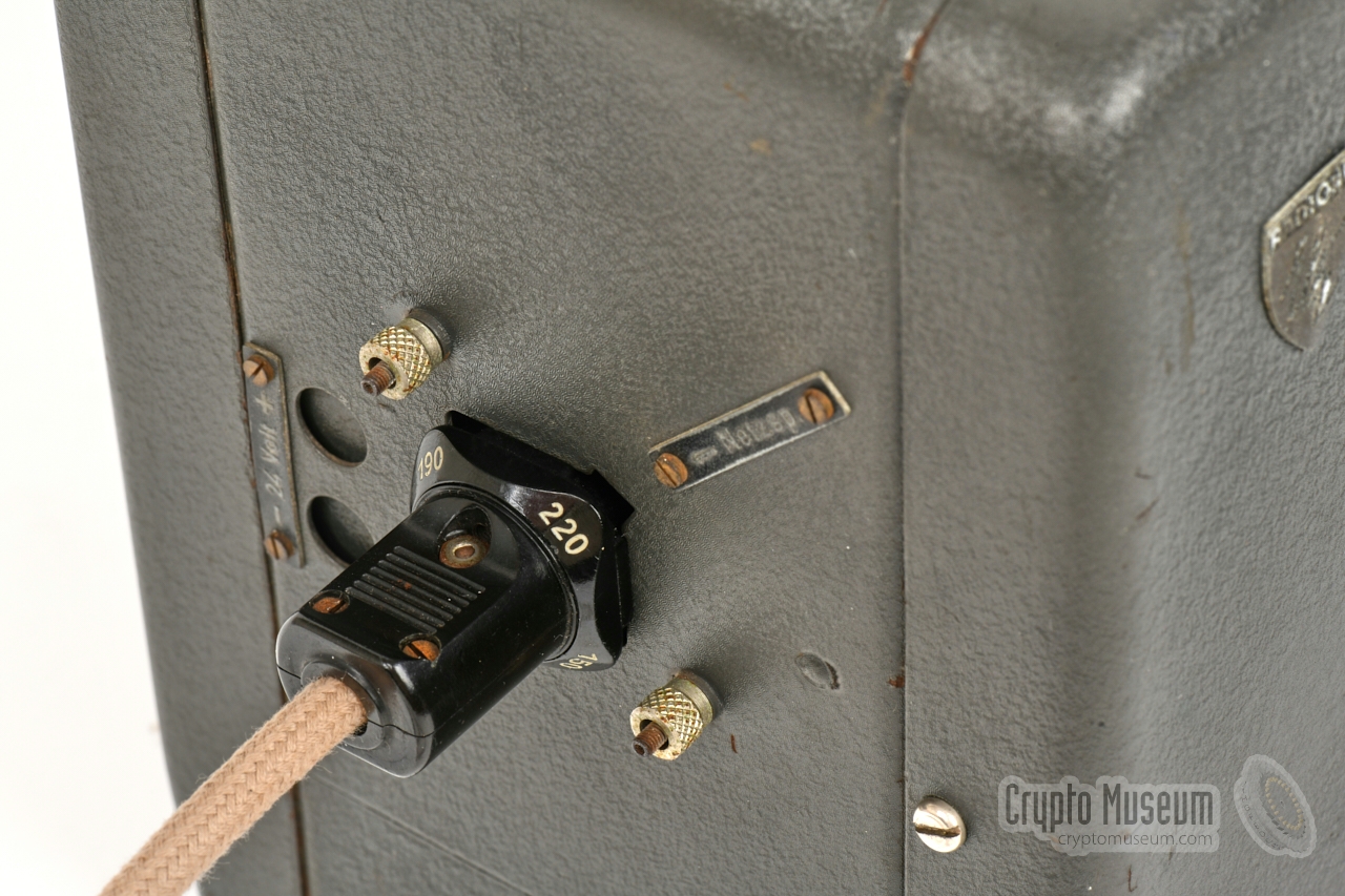
The RS-20/M can be powered directly from the AC mains, for which
a cable with a special plug was supplied as shown in the image
on the right.
The plug can be inserted into the mains socket on the
left side of the transmitter,
in four ways, each representing a different
AC mains voltage: 110, 150, 190 or 220V. The number in the
top right corner
specifies the selected voltage.
|
|
|
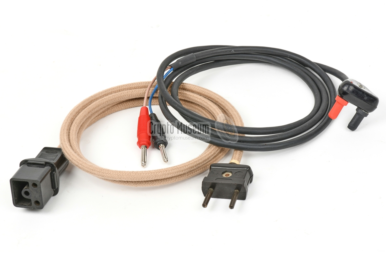
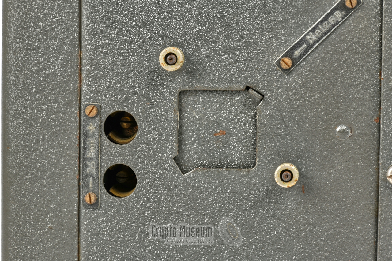
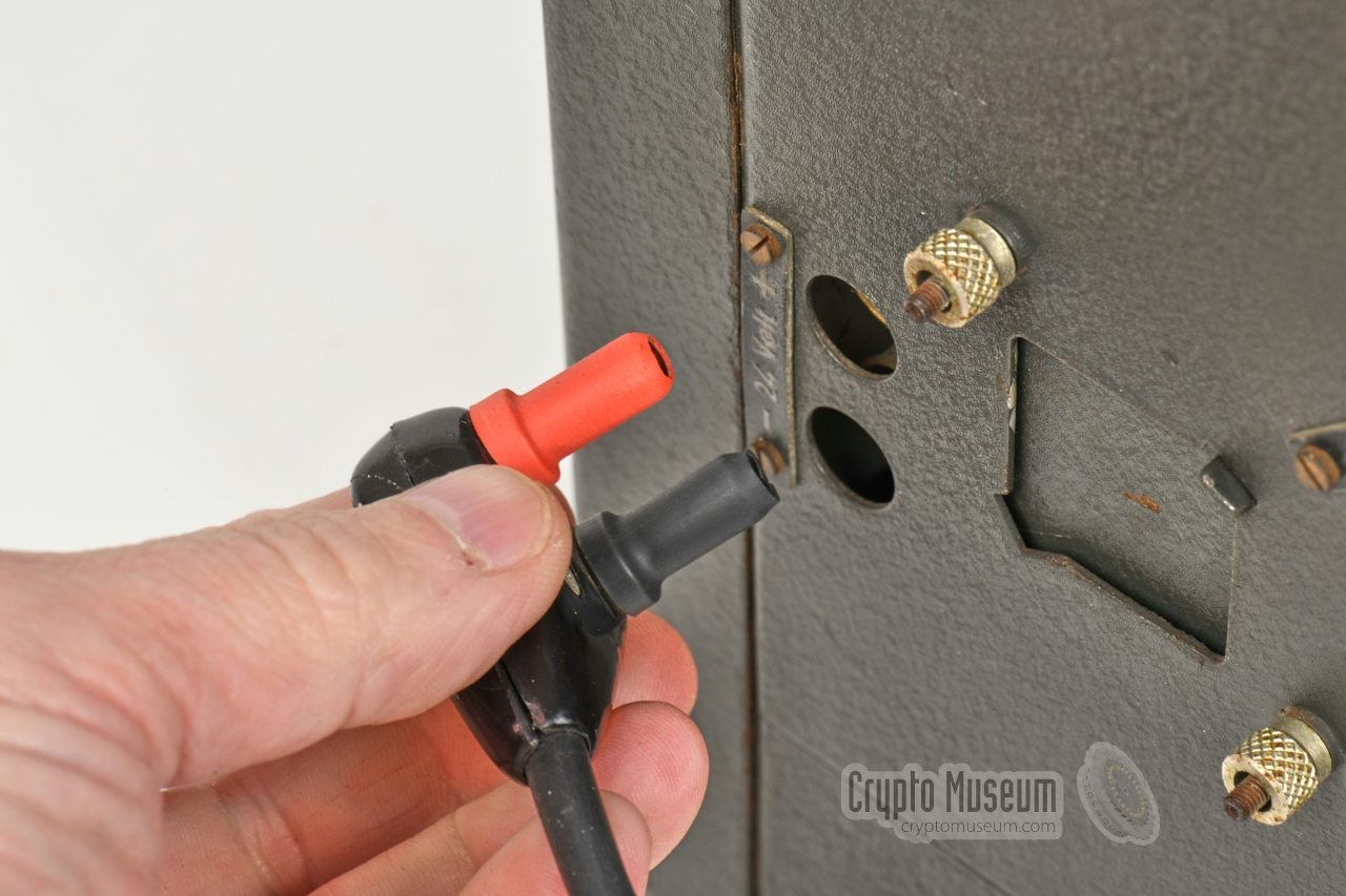
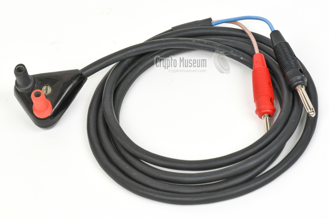
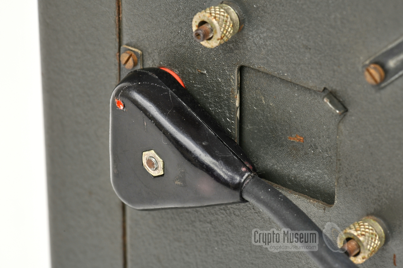
Instead of the mains AC network, it is also possible to power the
RS-20/M from a 24V DC source, such as the battery of a truck.
For this, the two-pin socket
to the left of the mains socket should be used. The upper pin is the (+).
When using the 24V DC terminals,
the mains AC socket is covered by a
hinged metal blanking plate. The DC power cable shown here, is an
aftermarket reproduction.
|
|
|
A complete Radione radio station consisted of a Radione RS-20/M transmitter
and the matching Radione R-3 receiver. A special cable set was supplied
with the complete set, to allow the two devices to be connected to a single
antenna.
In addition, the headphones output of the receiver was 'diverted' via the
transmitter, so that a sidetone could be injected when transmitting messages
in morse code CW.
At present, no image of a suitable cable set is available.
|
|
|
|
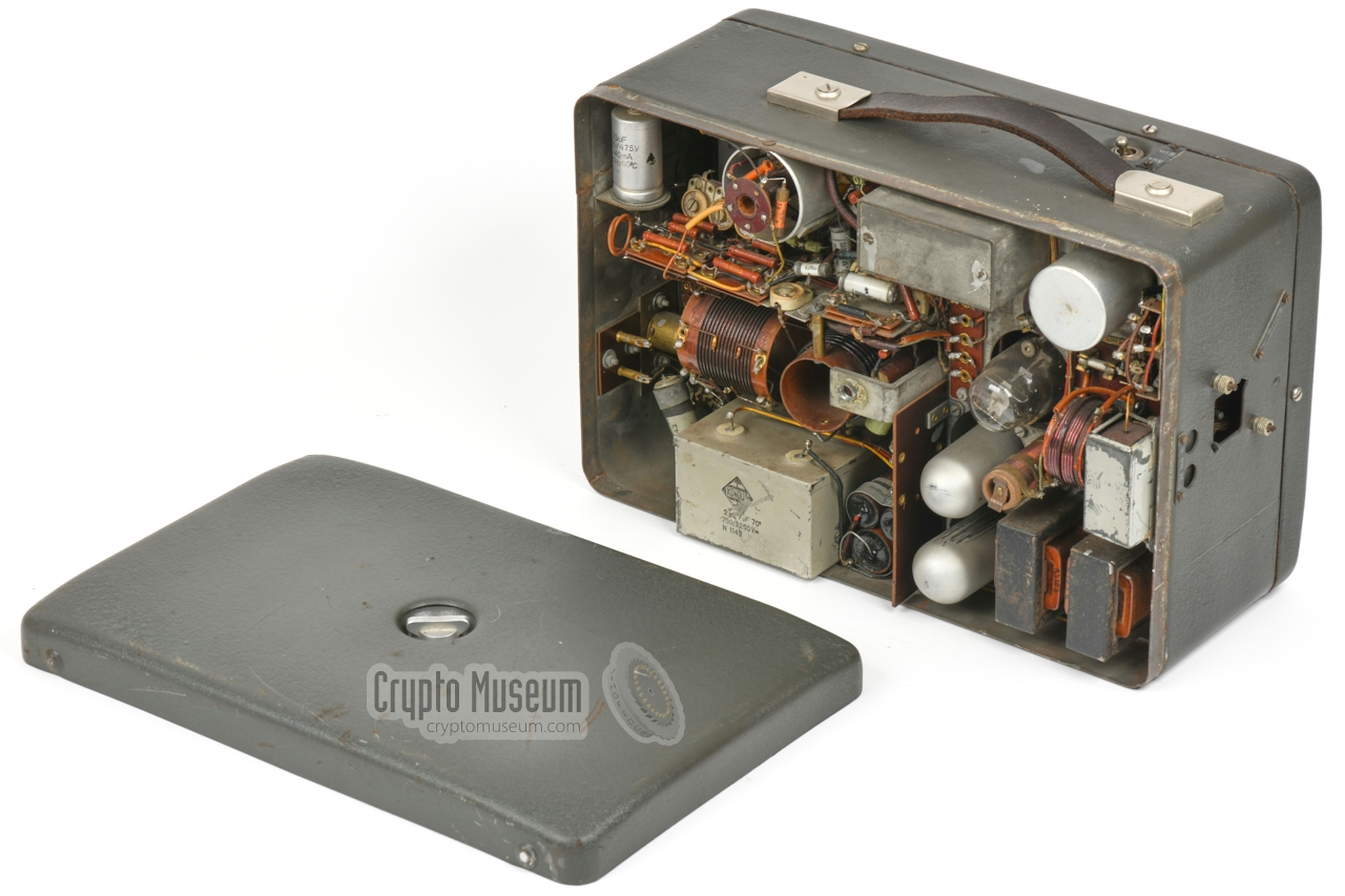
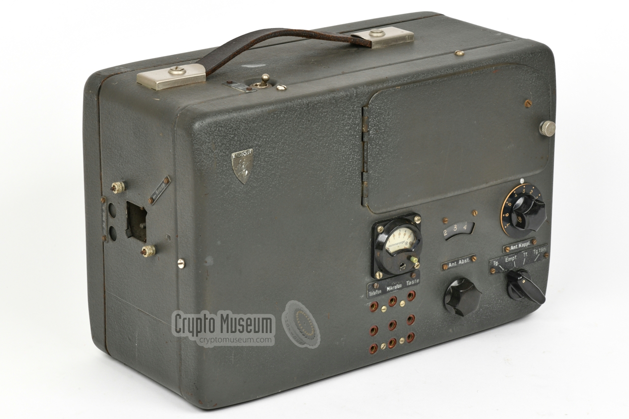
The RS-20/M is housed in a molded steel enclosure that has two removable
panels: one at the front and one at the rear. Removing the front cover is not
immediately useful and should be avoided if possible. Removing the rear panel is necessary
in order to gain access to the interior.
|
This is done by removing the large bolt at the centre of the rear side,
after which the rear panel can be removed. This may require some effort as
the panel may be binding to the enclosure itself.
The image on the right shows the interior of the RS-20/M after the rear
panel has been taken off. Inside the device is a metal chassis that holds
most of the components. With exception of the mains transformer — which is
mounted at the other side of the chassis, at the bottom left —
most parts are directly visible and accessible.
This makes the RS-20 a service friendly device.
|
|
|
|
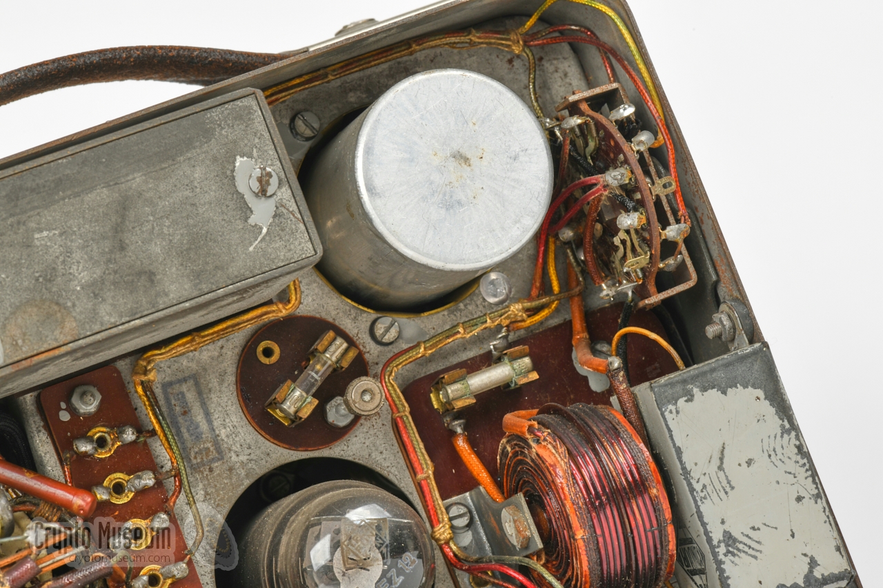
At the left side (right in the above image) is the power supply unit (PSU),
which allows the device to be powered by the 110, 150, 190 or 220V AC mains
network, or by a 24V DC source, such as the battery of a truck. In the latter
case, the internal vibrator
– in the upper left corner – is used.
|
The PSU is built around a mains transformer (not visible here)
with extra windings for the vibrator,
several choke coils, an EZ12 rectifier valve
and two voltage stabilisers.
Switching between the mains AC network (Netz) and a 24V DC battery,
is done by a rotary
switch that is mounted aside the vibrator.
It is controlled by a pivoting panel at the
left side that
covers the unused socket.
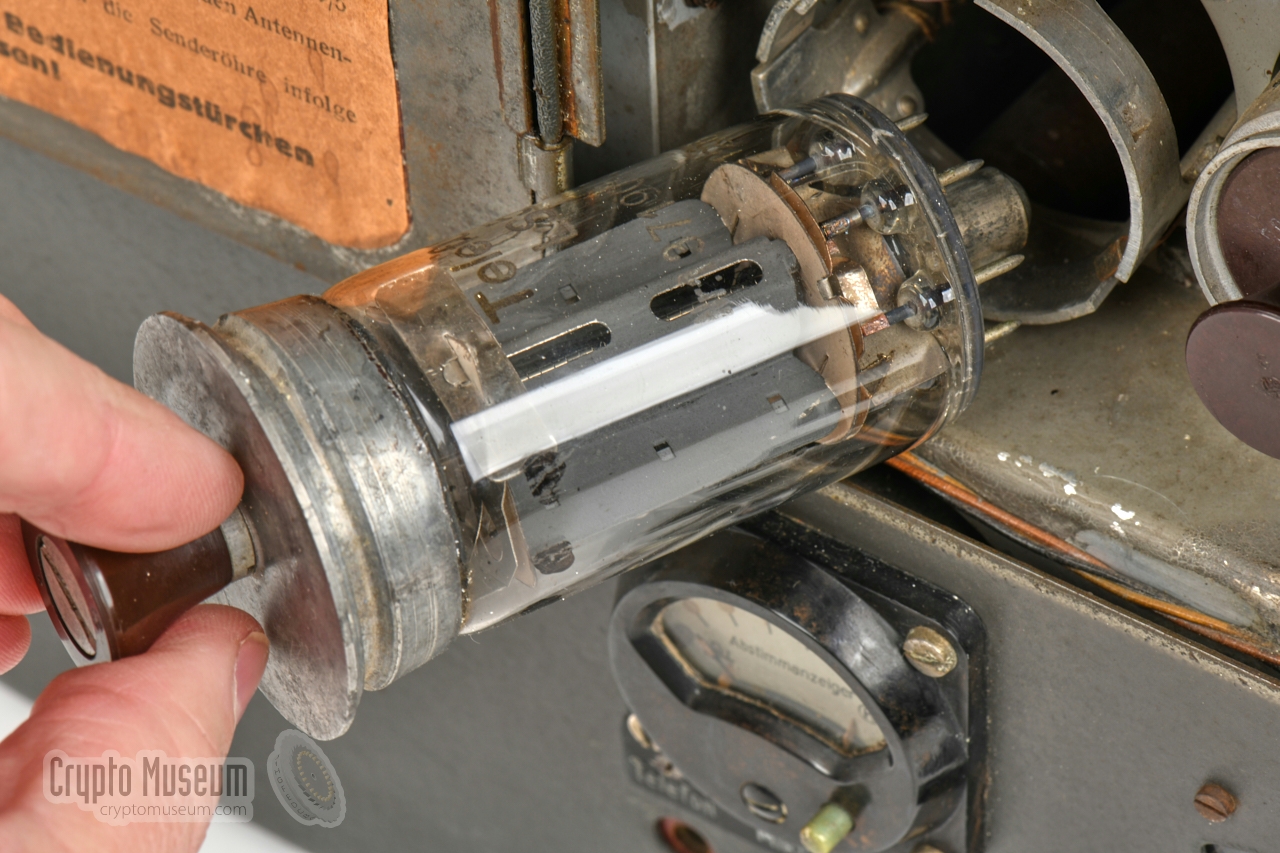
The remaining space inside the case is taken by the actual transmitter,
of which the valves are accessible via the hinged door at the front
panel. The image on the right shows the large PA valve.
|
|
|
|
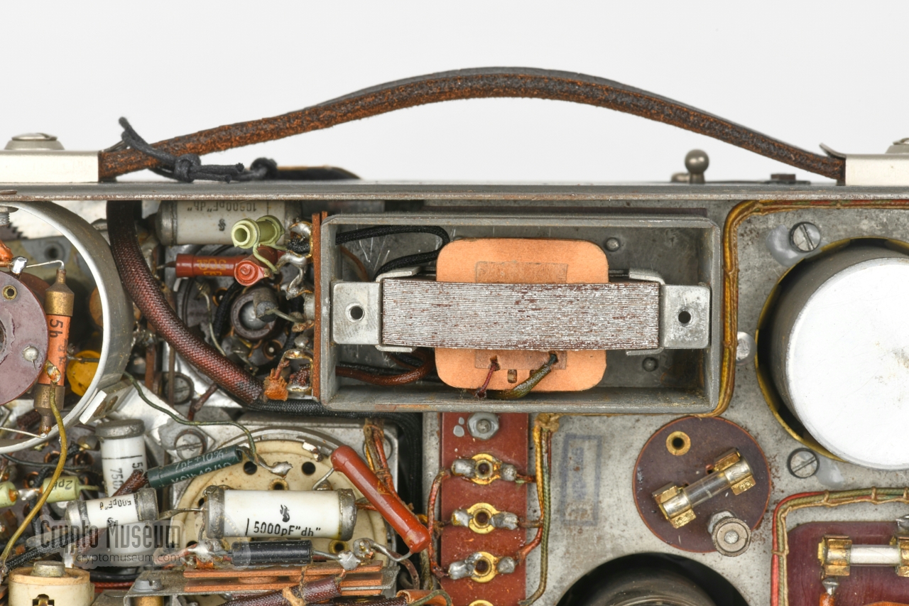
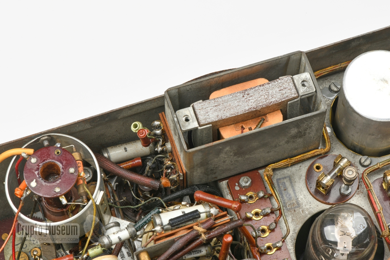
The passive components, such as resistors, capacitors, inductors, etc.,
are mounted directly to the contacts of the valve sockets, or on
pertinax carrier boards. At the top of the case, close to the modulator
valve, is a rectangular metal enclosure that contains the
modulation transformer.
|
It is only used when a carbon microphone is connected to the transmitter.
The output of the modulator is injected directly into the PA stage,
resulting in an Amplitude Modulated (AM) signal.
Next to the modulator is the oscilator valve, which is responsible for
generating the output frequency, based on the selected band and the crystal
that is installed at the front panel. From the oscillator, the signal is
passed to the Power Amplifier (PA) valve,
via a coupling transformer that can be tuned separately with a knob
at the front panel, marked Zwischenkreis Abstimmung.
|
|
|
|
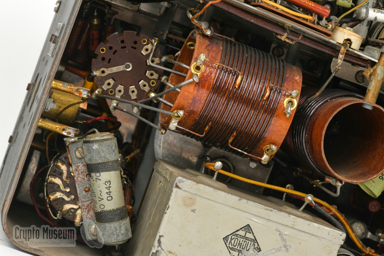
The PA valve delivers its signal to the antenna, via the large tank coils
shown in the image above. An additional perpendicularly mounted coil
provides a correction for each of the three frequency bands.
The tank coil has 7 taps, selectable from the front panel,
to find the best possible match, which can be tuned with a
front panel controllable variable capacitor that is mounted behind it.
|
Below is the circuit diagram of the RS-20/M. The upper half comprises the
power supply unit (PSU). This is a complex circuit, as the unit can be powered
by various AC mains voltages, as well as by an external 24V battery (DC).
In the latter case, a vibrator pack converts the 24V DC to AC.
At the top left is the mains socket,
of which two adjacent contacts are used at any time.
Switch S1a/S1b acts as the ON/OFF switch.
Switch S2 (S2a-S2f) is used to select between AC and DC,
and is shown here in the AC position. It is operated by the
pivoting flap
that covers the unused socket at the left side panel.
Note that the filaments of V1 and V2 are series connected when using an
external DC power source, and connected in parallel when AC
power is used.
At the top right is the EZ12 rectifier valve
that provides the raw 600V HT
voltage. This DC voltage is lowered to 300V, which is stabilised by two
GR150DA valves that are connected in series. There is tap on the secondary part
of TR1 for the negative supply (V-) and a separate winding
for the microphone bias voltage Vb.
Note that the MODE selector (S3) has 10 decks (S3a-S3j) and touches many
aspects of the entire circuit, depending on the selected mode: CW (morse),
RX (reception), AM (phone) or MCW (tone morse).
It is shown here in the leftmost position (CW).
The lower half of the diagram is the actual transmitter, which is built
around three valves: an LV1 modulator (V1), an LV1 oscillator
(V2) and an LS50 power amplifier, or PA (V3).
Note that in CW and MCW modes, V1 is used as a sidetone generator.
Audio from the R-3 receiver is
connected to the blue RX socket at the top left. It is looped to the headphones
when S3 is in RX mode. In all other modes, the audio from the modulator (V1)
is passed to the headphones, which is either speech from the microphone
(in AM mode)
or a CW sidetone when sending morse code.
The oscillator (V2) uses a crystal (XTAL) at the fundamental frequency. The
output is delivered via an adjustable transformer (L2) to the PA stage (V3).
S4a is the band switch, which selects one of three pre-adjusted trimmers.
The tuned circuit of the PA (V3) consists of a variable capacitor with
a large tank coil (L1a) in parallel. The tank coil has 7 taps,
selectable with switch S5.
S4b is the second half of the band switch, and selects an
additional coil (L1b) that is mounted near L1a.
At the bottom right is the meter circuit, which measures the antenna current
using a pickup transformer (TR3) and a rectifying circuit. When the small
button on the meter is pressed, the meter shows the power output of the
oscillator (V2), using a pickup coil in transformer L2.
➤ Original (barely readable) circuit diagram
|
|
When we received the RS-20/M featured on this page, it was dusty but
in very good cosmetic condition.
The previous owner had last operated the device more than 10
years earlier, so we knew it was complete [1].
It was likely however that it would not work straight away after 10+ years
of storage, and that the electrolytic capacitors would probably have
deteriorated by now.
|
|
After checking the internal wiring, it was decided to connect the device
to an AC power source, and gradually increase the voltage with a VARIAC,
to allow the electrolytic capacitors to reform themselves. It soon became
clear however, that the device was dead and no current was flowing.
|
Checking the parts at the primary side of the mains transformer, revealed
that corrosion had built up between the mains fuse and its socket. After
cleaning both fuse sockets with a dental drill and replacing the
fuses, the power ramp-up was repeated. This time current was flowing and
the mains transformer produced a soft hum.
The filaments of the valves all heated up nicely and the
EZ12 rectifier produced an HT voltage
of approx. 600V DC. It soon became clear however, that one of the electrolytic
capacitors had not survived the years and was rapidly running hot.
|
|
|
|
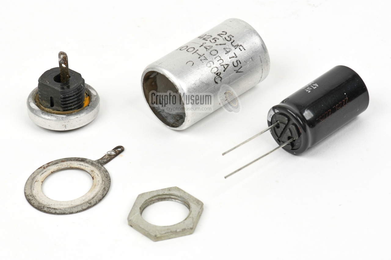
This is typical for aluminium foil capacitors of the era.
In order to preserve its characteristic look, it was carefully opened,
after which the guts were removed, and replaced by a modern capacitor.
Once this was done, the enclosure was glued back
together and placed back in the transmitter.
|
The image above shows the shell of the original capacitor, together with
a modern equivalent, that fits nicely inside the old aluminium shell.
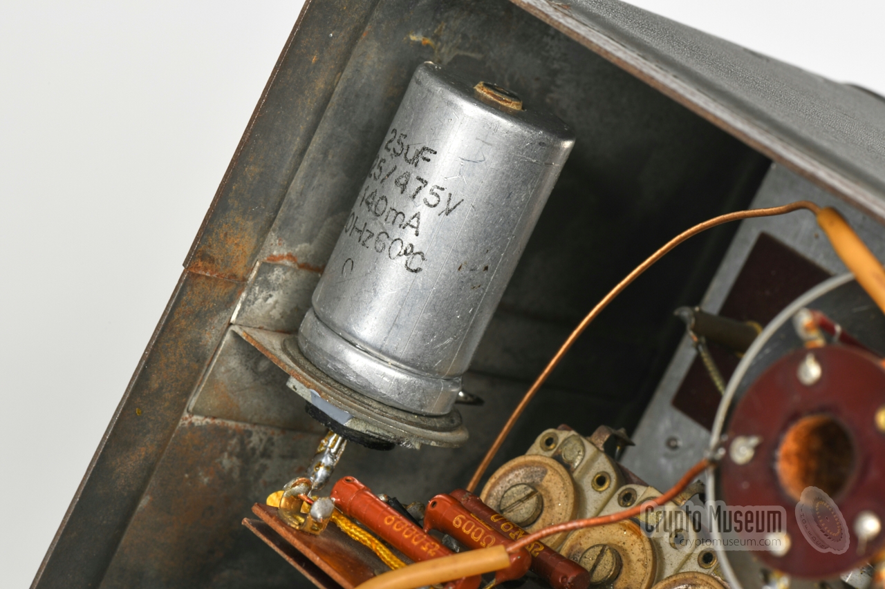
The image on the right shows the final result.
The device was powered up again and this time the capacitor remained cold,
whilst the 300V rail – to which it is connected – was stable and clean.
Furthermore, the mains transformer was no longer humming.
The device was left on for a while, to see if any other capacitors would
heat up, but this was not the case. As they are of the oil-filled type,
they are far less prone to aging.
|
|
|
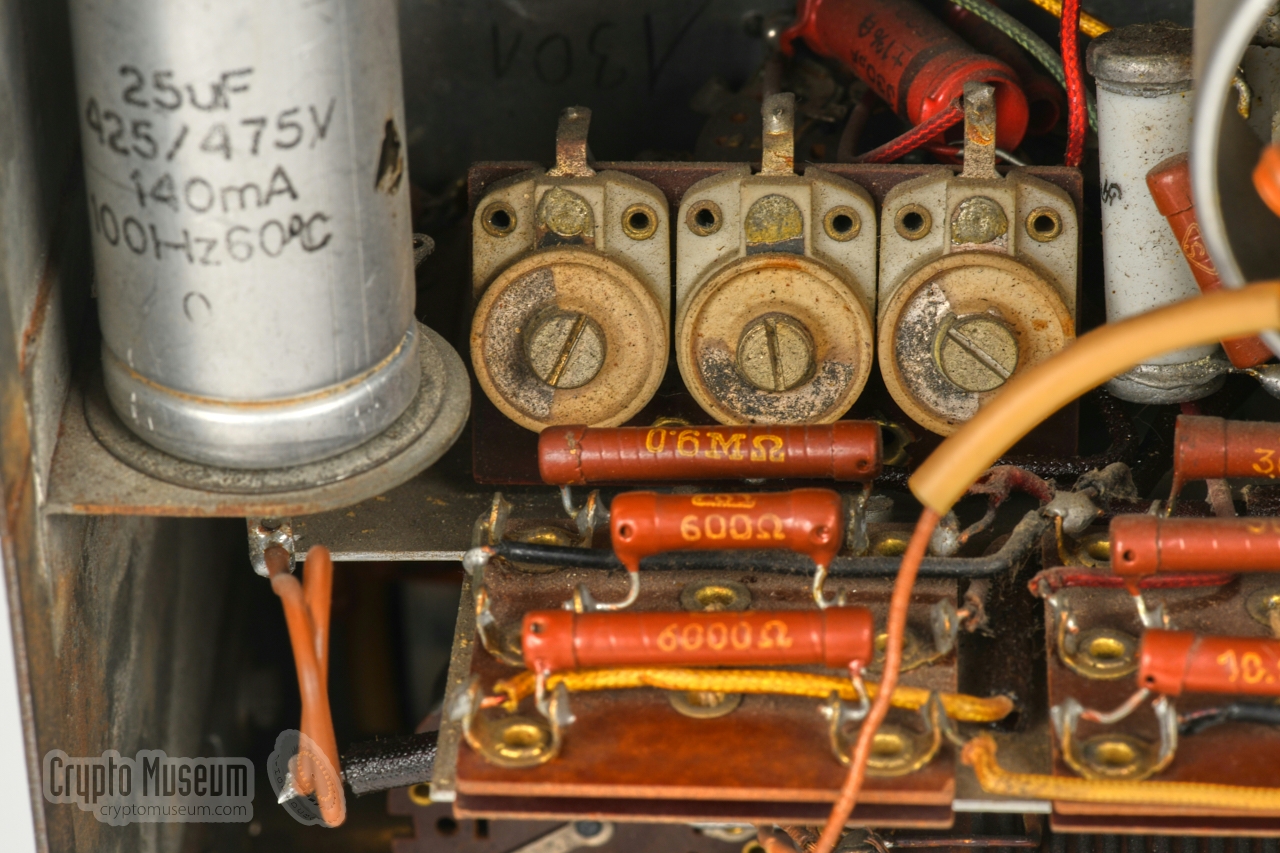
Note that the large double oil-filled capacitor that is mounted at the
bottom, has a date code of week 11 of 1943, which means that it is more
than 77 years old (2020). Also note that in some RS-20(M) units,
two paraffin-filled capacitors were fitted in this place, which are less
reliable and must be replaced as soon as possible.
As no further defects were found, a quartz crystal was installed and a morse
key was connected. The device worked straight away and produced a stable
tone when the key was held down. All four MODES were checked and worked as
expected.
So far, the following restoration work has been carried out:
|
A few weeks before we restored our RS-20/M, our friends Arthur Bauer
and Hans Goulooze restored the RS-20/M from Arthur's collection. In their
case they had to replace all electrolytic capacitors inside the device.
A description of the restoration is available on
Arthur's website,
complete with video footage [5].
Note the small manufacturing differences between Arthur's device and ours.
➤ Radione RS-20/M on Arthur Bauer's website
LV1 is a low-noise pentode, developed by
Telefunken for use in wideband
amplifiers and driver stages in transmitters. It has an 8-pin socket and
a removable bakelite knob at the top for easier in-field replacement.
In the SR-20(M), the LV1 is used for the oscillator (V2) as well as for the
modulator/sidetone generator (V1).
Below is the pinout as seen from the bottom of the valve.
➤ LV1 datasheet
|
LS50 is a transmitter pentode, developed by Telefunken especially for use
in airplanes. According to the datasheet, it was also approved for use by
the Army and the Navy. It requires a filament voltage of 12.6V (0.7A) and
develivers approx. 20W. Below is the pinout as seen from the bottom.
➤ LS50 datasheet
|
EZ12 is a double rectifying valve, made by Telefunken, that is typically
used for creation of the HT voltage in receivers and transmitters.
Below is the pinout as seen from the bottom of the valve.
➤ EZ12 datasheet
|
GR150/DA is a neon voltage stabiliser, which trips at 150V. Two of these
are used in series, so that the threshold becomes 300V.
In the Radione RS-20(M) however, they are used as a voltage limiter, to
ensure that the voltage on the power rail never exceeds 300V when not
transmitting.
➤ GR150 datasheet
As soon as the transmitter is enabled, the current increases, and so does
the voltage drop over the 10kΩ series resistor. As a result the
voltage on the power rail will drop to below 300V,
and the the two GR150 valves will no longer light up.
Note that the GR150 has three electrodes rather than two.
The extra electrode (aa) is used as an ignition.
An appropriate equivalent for this valve is the GR20-12.
The drawing above shows the pinout as seen from the bottom of the valve [8].
➤ Backgrounds to 3-pin stabilisers
|
Circuits Crystal oscillator, RF power amplifier, modulator Frequency 3 - 14.2 MHz Bands 3 (see below) Crystals 12 (see below) Modulation AM (phone) CW (morse) MCW (morse) Output 20W (CW), 12W (MCW) Mains 110, 150, 190, 220V AC Battery 24 to 28.5V DC (external) Valves 2 × LV1, LS50, EZ12, 2 × GR150DA (stabiliser) Dimensions 350 × 240 × 174 mm Weight 12 kg
|
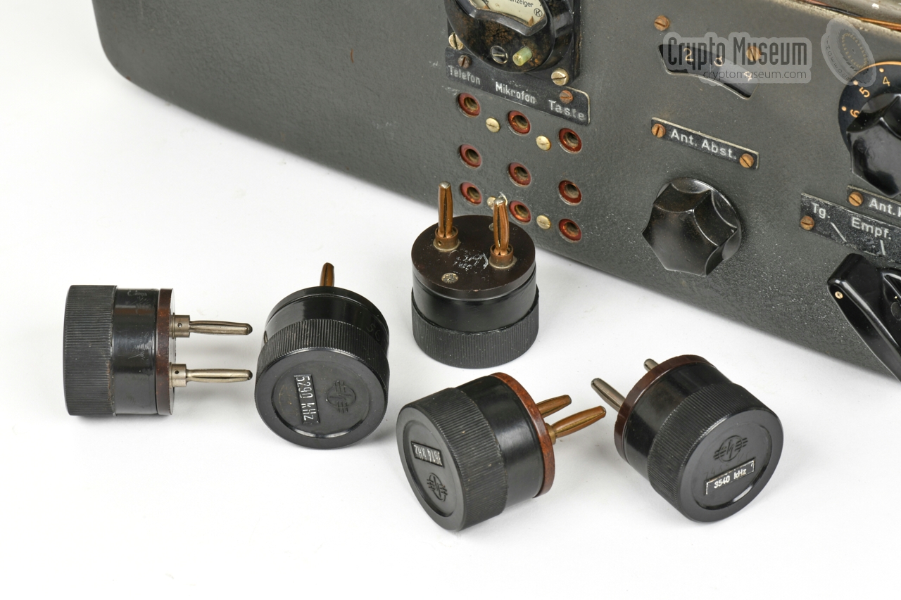
Red ● 3 - 5.1 MHz Black ● 5.1 - 8.8 MHz Green ● 8.8 - 14.6 MHz
|
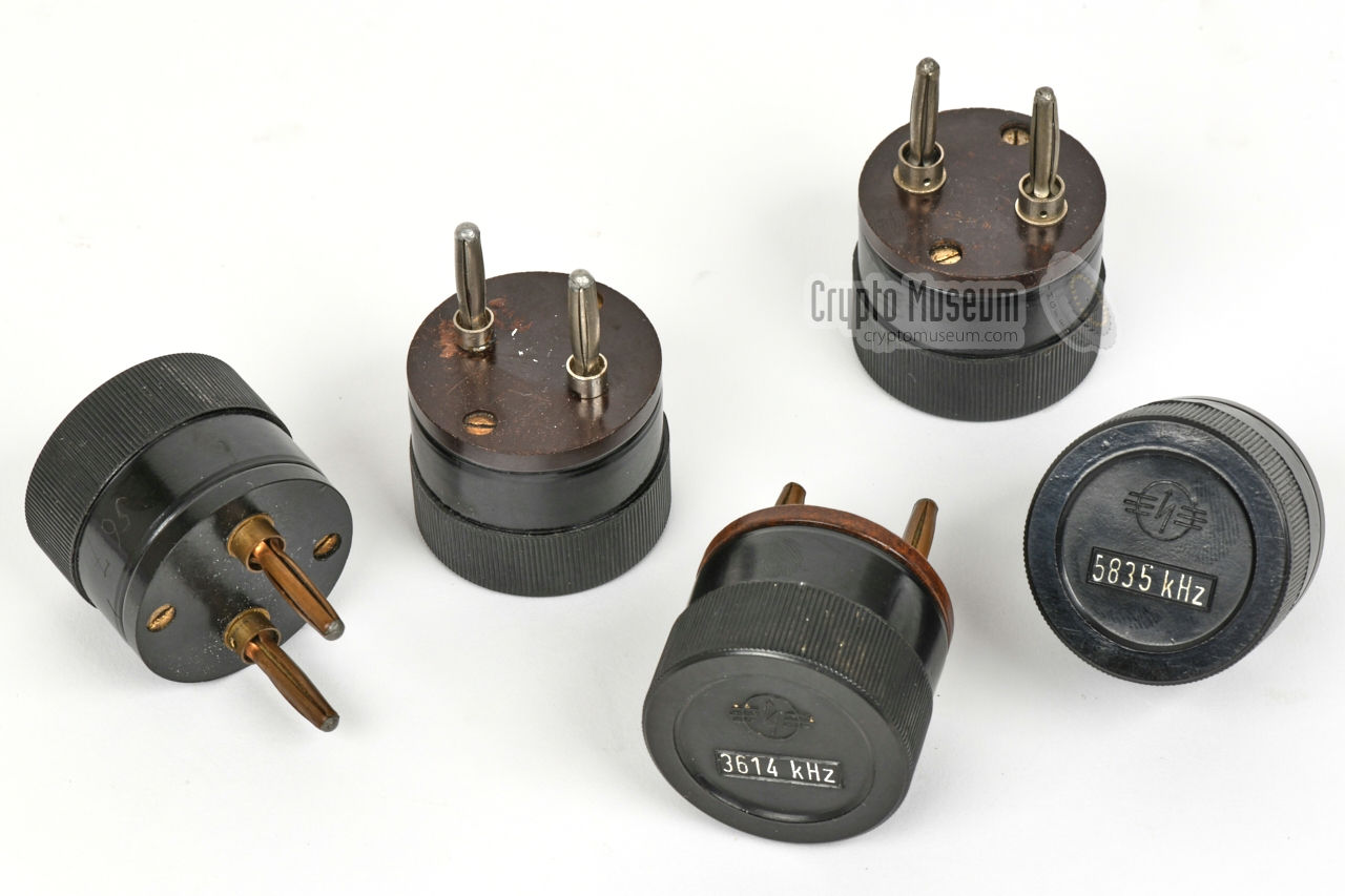
|
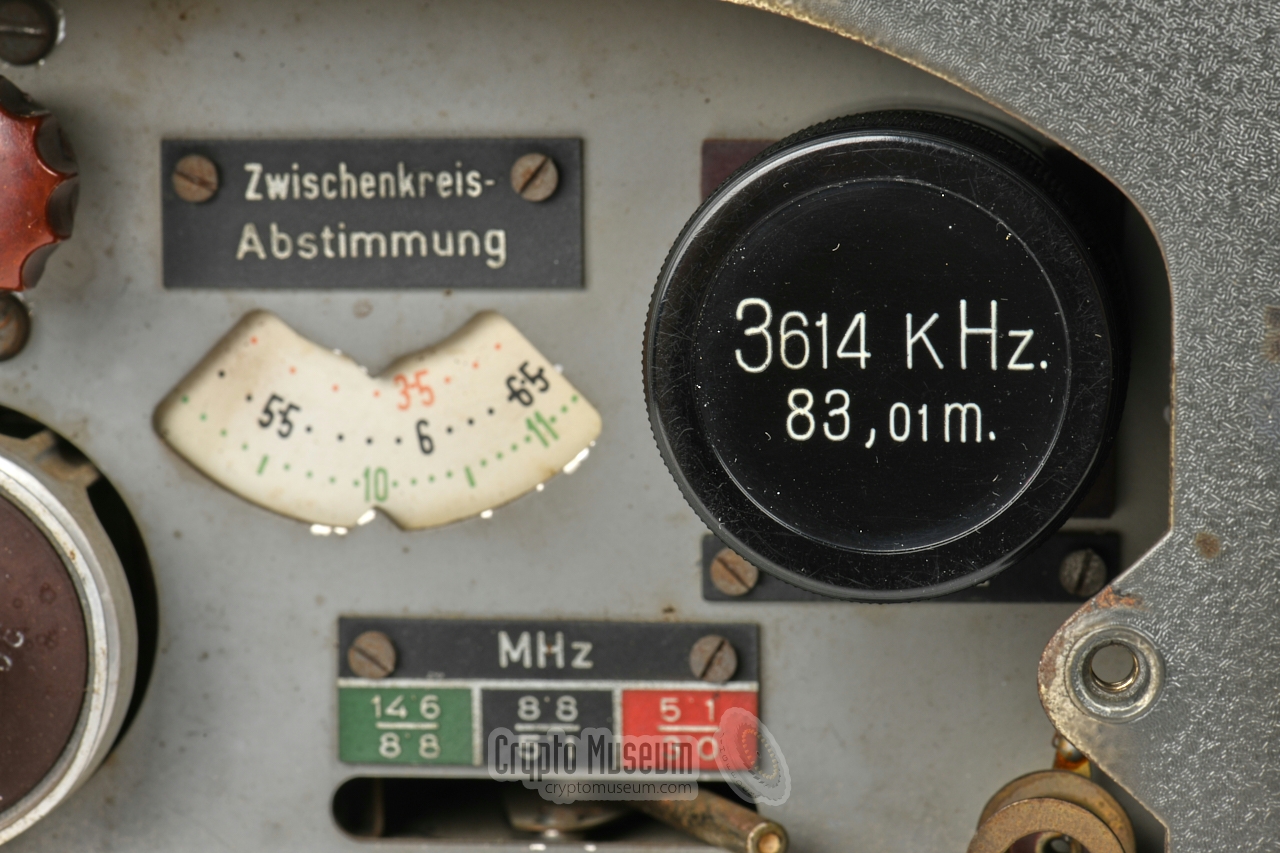
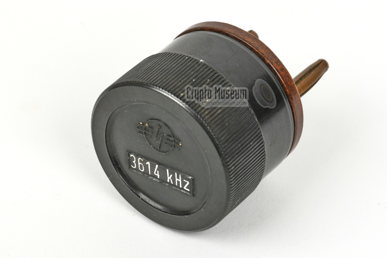
Each Radione RS-20(M) came with a fixed set of 12 crystals, stowed in a
grey wooden box. The following frequencies were supplied:
|
- 3300 kHz
- 3525 kHz
- 3614 kHz
|
- 3920 kHz
- 3978 kHz
- 4265 kHz
|
- 4820 kHz
- 5290 kHz
- 5835 kHz
|
- 5917.5 kHz
- 6240 kHz
- 6515 kHz
|
|
The following items are missing from the RS-20/M in our collection:
|
- Storage case
- Original manuals
Carbon microphone - Interconnection cables (to R-3)
- Wooden box with spares
- Wooden box with crystals
- Antenna cables
- Mains fuse cover
|
- Cor Moerman, Radione RS-20/M - THANKS !
September 2020.
- Arthur Bauer, Some Aspects of the German military Abwehr wireless service...
...during the course of World War Two
15 September 2003. p 6.
- Louis Meulstee, Radione R3 / RS20M
Wireless for the Warrior, Volume 4
- Unknown source, Image of German Funker in a bunker with Radione R3 and RS20M
Retrieved March 2018 from Peter Zijlstra (PA0PZD).
- Arthur Bauer, Personal correspondence
March 2018 - October 2020.
- Günter Hütter, Personal correspondence
March 2018.
- Jørgen Fastner, Personal correspondence
October 2020.
- Frank's Electron tube Pages (datasheets)
Retrieved October 2020.
- Nikolaus Eltz, Letter to Dr. Heinz Lissok
Wien (Austria), 29 May 1974.
|
|
|
|
Any links shown in red are currently unavailable.
If you like the information on this website, why not make a donation?
© Crypto Museum. Created: Sunday 25 October 2020. Last changed: Tuesday, 18 March 2025 - 08:53 CET.
|
 |

|
|
|


![Example of a Radione R3 and RS-20M being used in a German Wehrmacht bunker. Image via [3].](img/r3_bunker_large.jpg)
![Luftwaffe version of the SE-20. Photograph kindly supplied by Jřrgen Fastner [7].](img/303465/073/full.jpg)


![Original wooden box with quartz crystals. Photograph kindly supplied by Günter Hütter [6]](img/303465/065/thumbnail.jpg "image # 303465/065")
![Original wooden box with quartz crystals. Photograph kindly supplied by Günter Hütter [6]](img/303465/066/thumbnail.jpg "image # 303465/066")
![Full set of original quartz crystals. Photograph kindly supplied by Günter Hütter [6]](img/303465/067/thumbnail.jpg "image # 303465/067")
![Older type of quartz crystals. Photograph kindly supplied by Günter Hütter [6]](img/303465/063/thumbnail.jpg "image # 303465/063")
![Older type of quartz crystals. Photograph kindly supplied by Günter Hütter [6]](img/303465/064/thumbnail.jpg "image # 303465/064")

![Original wooden box with quartz crystals. Photograph kindly supplied by Günter Hütter [6]](img/303465/065/full.jpg)
![Original wooden box with quartz crystals. Photograph kindly supplied by Günter Hütter [6]](img/303465/066/full.jpg)
![Full set of original quartz crystals. Photograph kindly supplied by Günter Hütter [6]](img/303465/067/full.jpg)
![Older type of quartz crystals. Photograph kindly supplied by Günter Hütter [6]](img/303465/063/full.jpg)
![Older type of quartz crystals. Photograph kindly supplied by Günter Hütter [6]](img/303465/064/full.jpg)