|
|
|
|
|

|
|
WWII RX NL OD OD Set →
As far as we know, there were two generations of the receiver, which
differ in circuit design and enclosure.
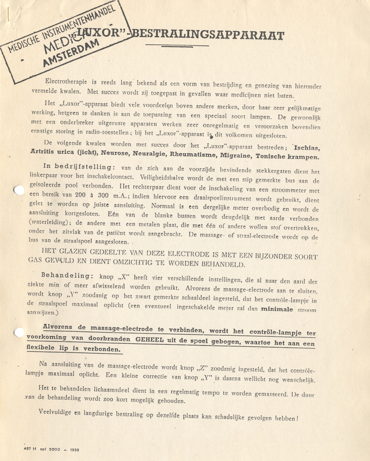
The first generation was based on three EF6 valves,
built on an aluminium chassis and housed in a
wooden cabinet, disguised as a
commercial LUXOR medical diathermy device [7].
It covered the 2.85-3.15 MHz (100 m) frequency range, which is about the same
as that of the OD Transmitter. A later version, developed by Dutch
radio amateur Jan Lourens (PA0BN), was housed in a home-made aluminium enclosure
of which the lid could easily be removed. It is shown here.
|
|
|
|
The later version had removable plug-in coils,
which made it suitable for
reception of the 31, 41 and 49-metre broadcast bands as well. About 34 of
this variant were built [3]. The receivers were series-manufactured by
the OD — probably in Zaandam and Eindhoven —
with components and engineering supplied by
Philips in Eindhoven (Netherlands).
In addition, the circuit diagrams were distributed to the various
OD Regions
allowing them to be built with locally sourced parts as well.
|
-
This is the frequency range of the initial design. A later variant
covered the 31, 41 and 49-metre broadcast bands as well, by using
plug-in coils. Furthermore, variations in the basic frequency
range are known.
|
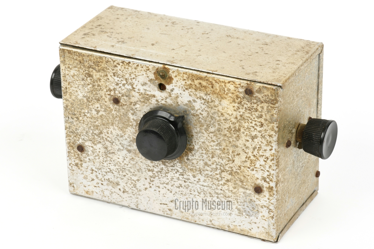
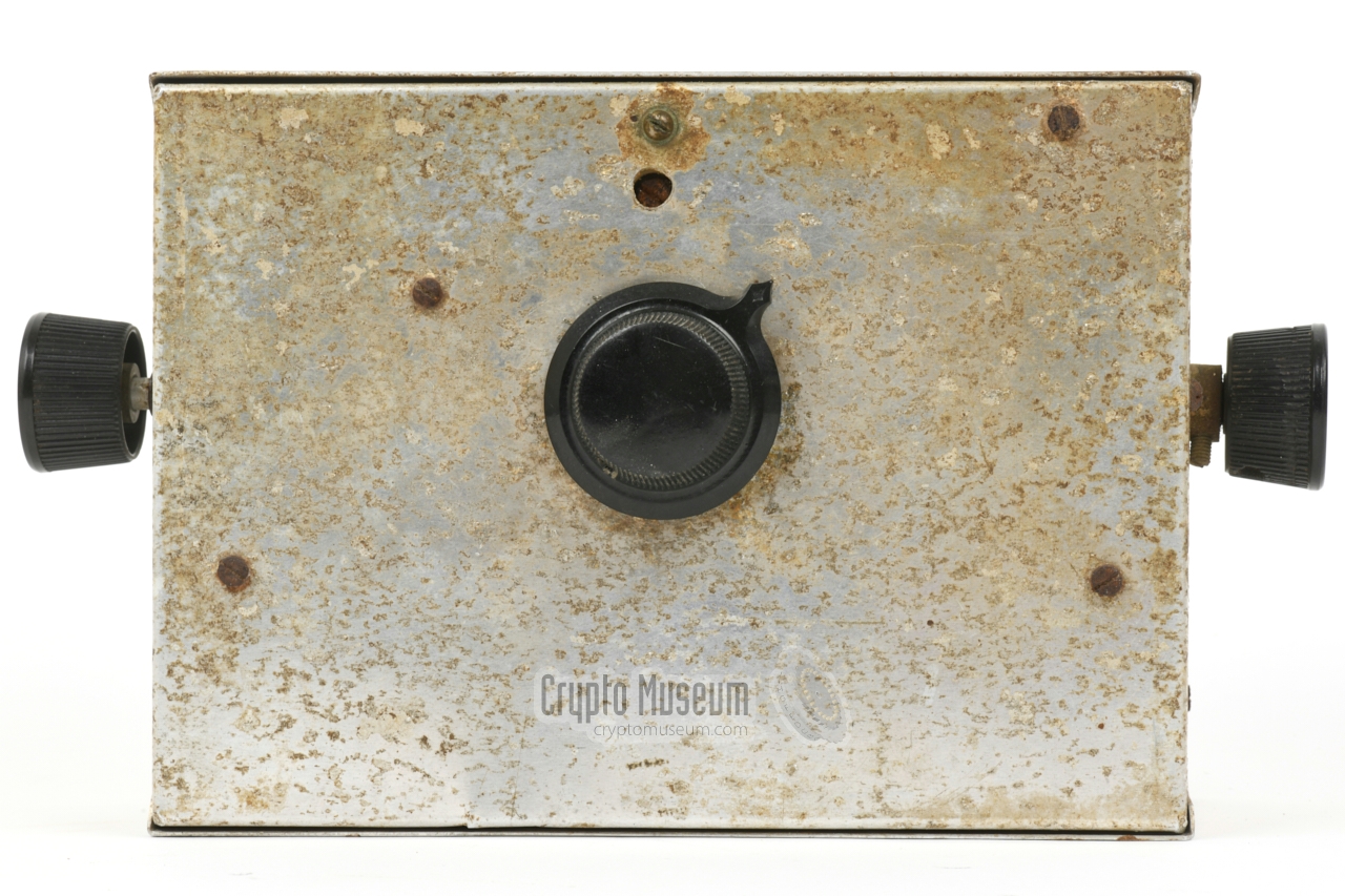
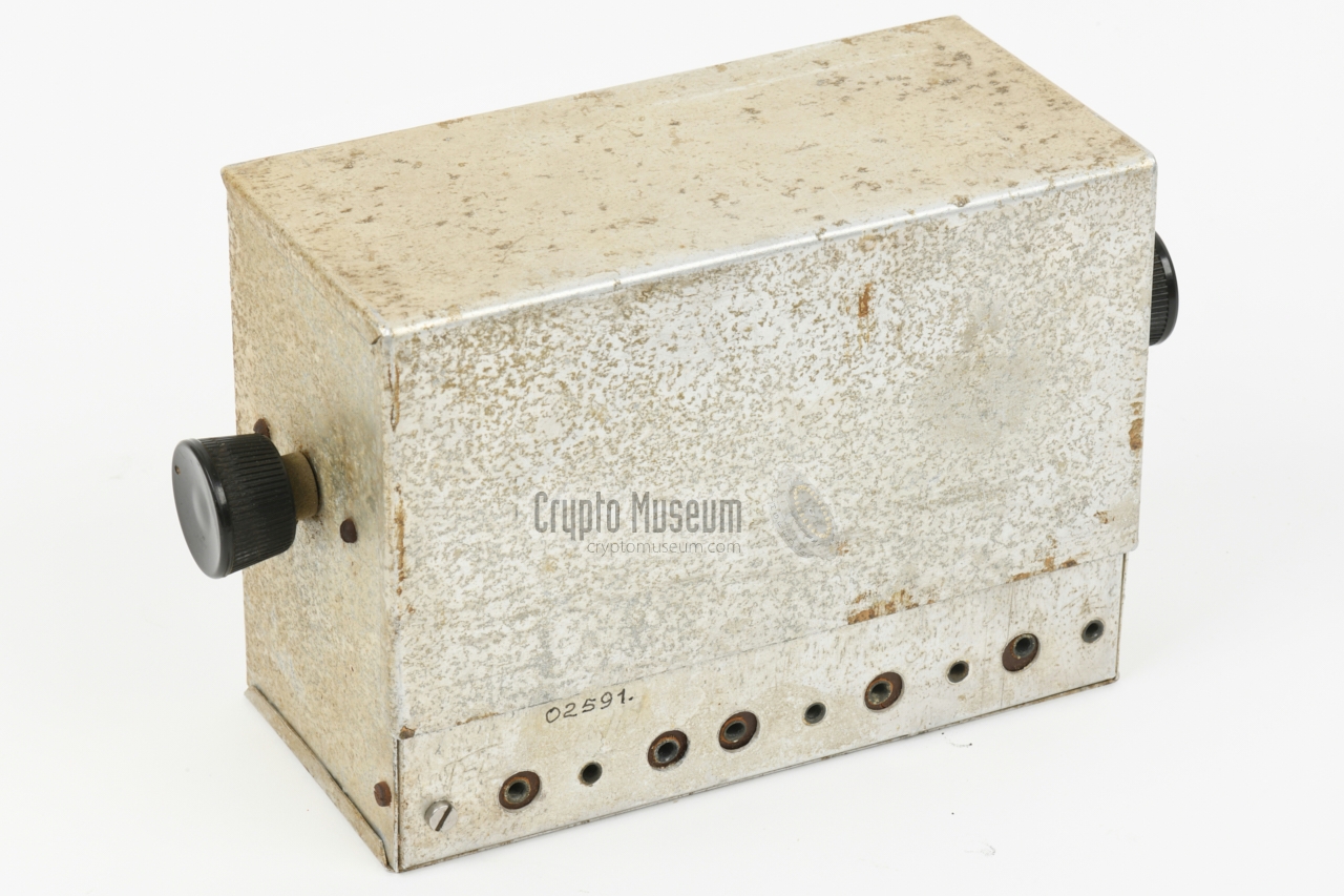
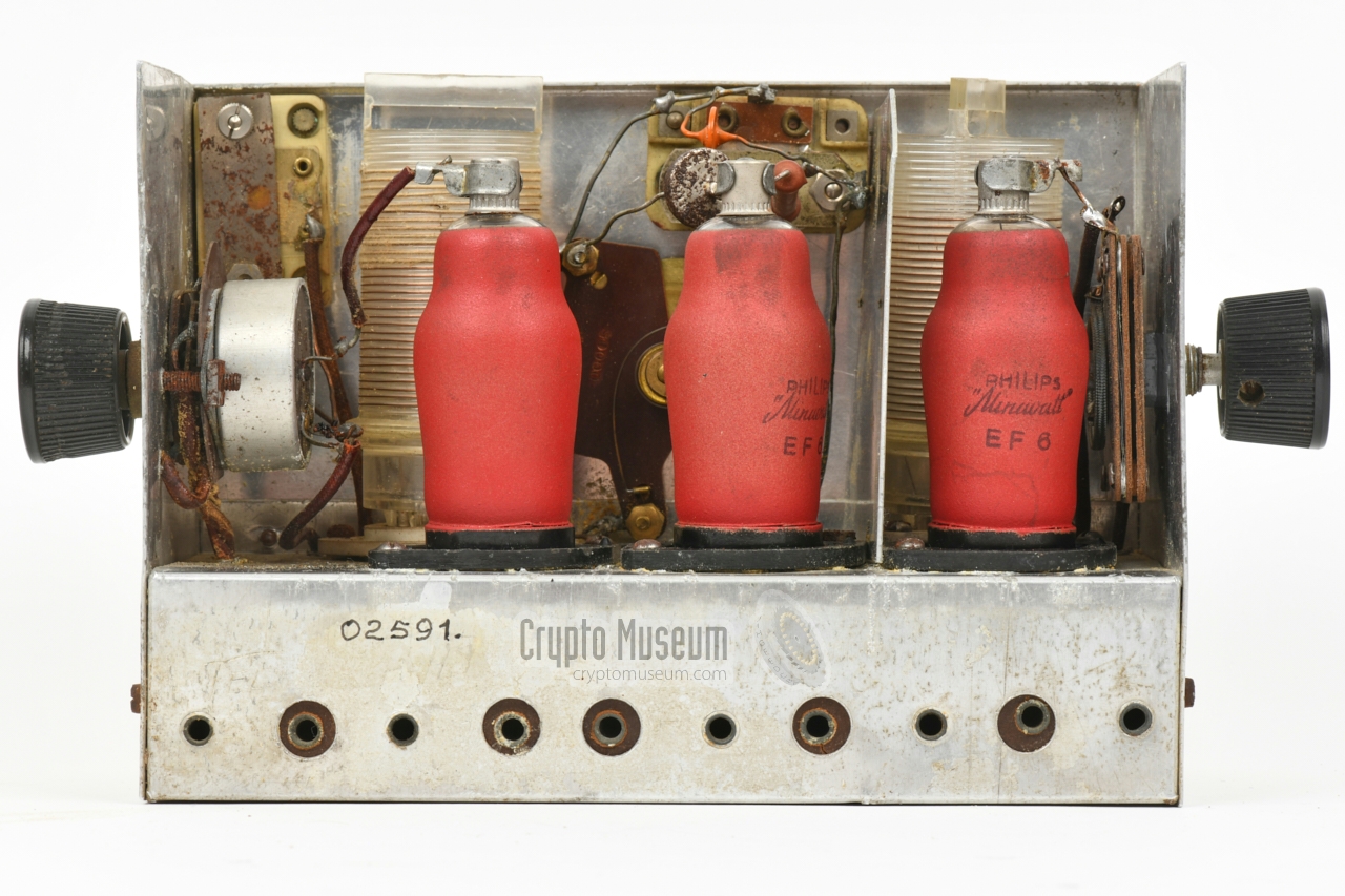
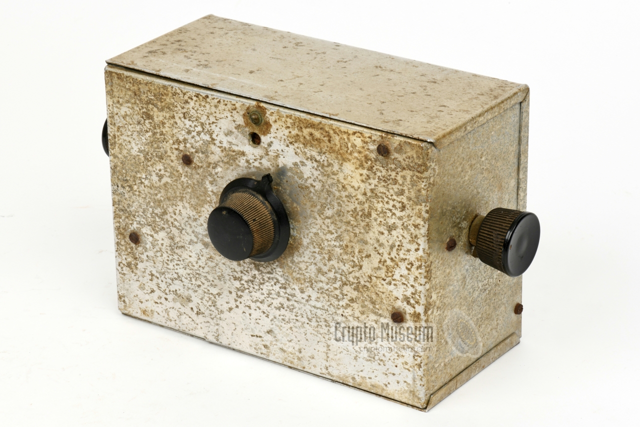
The diagram below shows the front panel of the second generation of the
OD Receiver. It is housed in a simple homemade aluminium enclosure that
measures 185 x 135 x 90 mm, and has bakelite knobs at three sides.
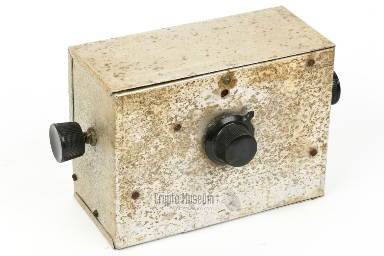
At the right is the volume knob with integrated ON/OFF switch. At the
left is the antenna tuning knob.
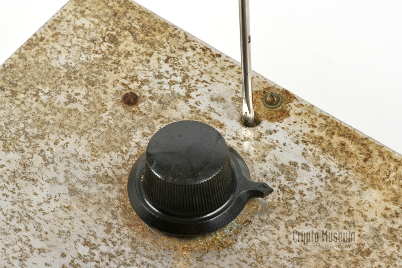
The frequency tuning knob is at the centre of the front panel, allowing
adjustment over a fairly narrow
frequency range of approx. 300 kHz around 3 MHz.
The precise centre frequency of the unit, can be adjusted with an
internal trimmer,
that can be reached
through a hole in the front panel,
just above the tuning knob. As the receiver is free-running, it
had to be calibrated regularly by means of an external source,
such as a crystal-based transmitter, or an OD Transmitter
that had been calibrated with an external
wavemeter.
Note that, unlike many other receivers that use the same principle,
this version of the receiver does not have an external
oscillator/detector reaction control. Instead the feedback loop can be adjusted
with an internal trimmer.
An external reaction control was probably omitted,
because the receiver can only be adjusted over a limited range
for which a single reaction setting can be used. It can still be
adjusted easily, by removing the cover and setting the trimmer by hand.
|
Within the OD, engineer Jan Thijssen (1908-1945) was charged with
building a national radio network.
Anton van Schendel, an employee of the
Radio Monitoring Service (RCD) of the PTT,
became responsible for training
the operators, whom he recruted from radio amateurs (HAMs).
As secrecy of the messages was of the utmost importance,
B.J. Suermondt was tasked with the establishment of an encryption
bureau. He produced the coding instructions and trained the crypto-officers
of the region commanders. Each radio station was given common
code material.
After the reorganisation of the OD in 1942, the OD transmitters and
receivers were developed by ir. J.P. Heyboer (1912-1945), who had been
made available by
Philips in Eindhoven, and built in the
workshop of Jan Hendrik (Henk) Op den Velde 1 in Zaandam,
and probably also somewhere in Eindhoven.
Philips also supplied the
required components, under control of ir. G.H. Thal Larsen (1899-1963) and
radio technician H.A. Hoekstra [4].
The design of the OD Receiver was later improved by Jan Lourens (PA0BN)
in Oosterbeek (Netherlands), who built at least 34 of them.
After Op den Velde was arrested on 2 March 1944, Hoekstra took over his
work on the roll-out of the national radio network. In the south of the
country, Heyboer had meanwhile completed the south part of the network
and had taken over the activities of Jan Thijssen on 31 December 1943,
after the latter had been expelled from the OD, due to a conflict
with the OD management. 2
This image shows the radio station of
OD Region 6,
when it was located in the city of Apeldoorn.
At the left is the first version of the receiver, which is housed in a
wooden enclosure. All knobs and the sockets for the headphones are at
the front panel. At the right is the OD Transmitter with the two
PE06/40 valves and no enclosure. The name of the operator is currently
unknown [3].
The image above shows the clandestine radio set of
Region 11,
when it was located in Zaandam in April 1945 [3]. The receiver is visible at
the centre of the picture. It is one of the later versions, which has
an output transformer on the chassis
and a reaction potentiometer at the front panel. The
transmitter is at the left. The one shown here was modified by
radio amateur J. Zandbergen (PA0ZY) to a Master Oscillator/Power Amplifier
circuit. At the front left is a rotary DC converter.
The image above shows the same radio station of
Region 11,
this time photographed in
late 1944 when it was located at a hospital in Alkmaar. In this image, the
extra knob at the top right of the front panel of the receiver – used
for the reaction potentiometer – is clearly visible [3].
The image above shows the setup of the radio station of
OD Region 15
when it was located in Grijpskerke (near Middelburg) in 1944.
It is similar to the
setup of Region 11 in the hospital of Alkmaar,
but with a slightly different receiver that does not have a reaction
knob at the front panel. It is unclear which design came first.
The receiver in our collection, is of this type.
|
 |
-
During the war, Henk op den Velde was known by the codename HEIN [5][6].
-
Thijssen found the OD too passive and wanted to increase the use
of the radio links with the UK. After he left the OD, he formed
the new resistance organisation
Raad van Verzet (RVV) —
the Resistance Council.
|
Below is the circuit diagram of the OD Receiver, as published
by Louis Meulstee in the book Wireless for the Warrior, Volume 4 [3]. This circuit
was reportedly designed during the war by radio amateur Jan Lourens (PA0BN) in Oosterbeek
(Netherlands). It is likely that the diagram was recreated from memory at the time
of the publication, as all component values are missing [3].
|
| |
Circuit diagram as published in [3]
|
It's a straightforward design, consisting of an RF pre-amplifier,
detector and AF amplifier, each built with a single
EF6 valve
[3]. The RF and AF stages are both transformer coupled.
It should be noted however, that this circuit differs significantly from the
OD Receiver in our collection [1][2].
Furthermore, the g3 of the EF6 is not internally wired to the
cathode (k) as shown in the diagram.
It is possible that Jan Lourens (PA0BN) mistakenly supplied the wrong diagram
at the time, or that the above is the original circuit diagram of the first
generation of the OD Receiver,
or that there was more than one design of the receiver.
It is known, for example, that a limited number of self-modified receivers
were made by radio amateur Piet Neve (PA0PN) in
OD Region 15 (Zeeland) [3].
|
| |
Actual circuit diagram as taken down by Crypto Museum [2]
|
Above is the actual circuit diagram, as taken down from the OD Receiver in
the Crypto Museum collection [1][2]. It is believed that it is the second
generation of the receiver, as it has
plug-in coils for the RF stage (L1)
and for the regenerative detector (L3/L4). The antenna signal is directly fed
to the g1 of V1 (no transformer), and the AF output is taken directly from
the anode of V3 (via C14). This means that a properly isolated pair of
high-impedance headphones had to be used.
Furthermore, the regeneration level of the detector (V2) is not controlled
by adjusting the g2 voltage of V2 with a potentiometer, but by adjusting
trimmer C8 in the feedback loop (L4).
The receiver covers only a small part of the 3 MHz band, with was pre-set
with C5 and C6 (reachable
through a hole in the font panel) and fine tuned
with the variable capacitor at the centre of the front panel (C7).
It is likely that C6 was roughly 'calibrated' with a pre-calibrated transmitter.
At the top right is the power switch, which is part of the volume control (P1).
It switches the LT only.
|
|
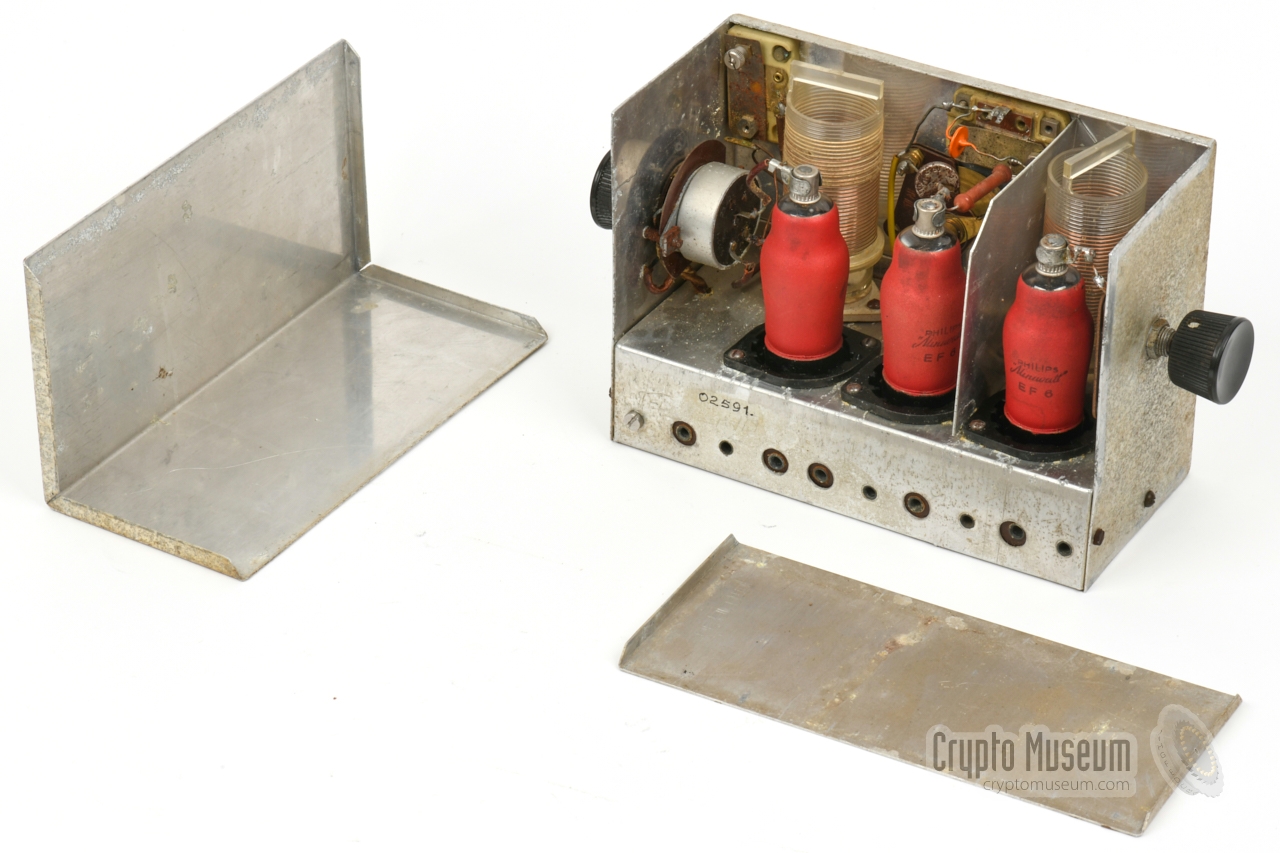
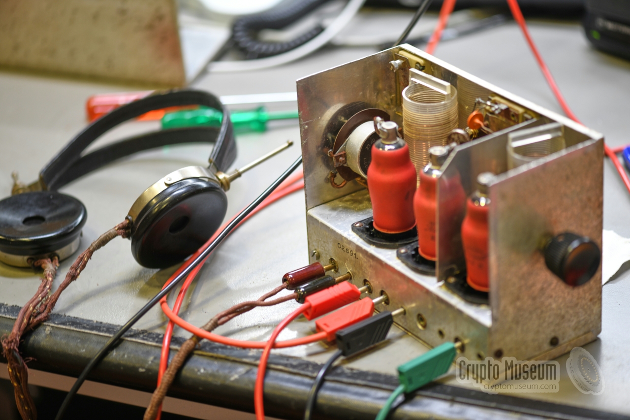
The OD Receiver is designed in such a way that the interior is easily
accessible without removing any screws. It is built on an aluminium chassis
and is housed in a bended aluminium enclosure. The interior is covered by
two removable panels: one at the top/rear and one at the bottom.
|
These two panels are simply clamped onto the case, and can easily be taken off,
as shown in the image above. This reveals the aluminium chassis that holds
all components plus the front and side panels. The image on the right shows
the enclosure as seen from the rear. Towards the bottom edge is a contact
strip with the sockets.
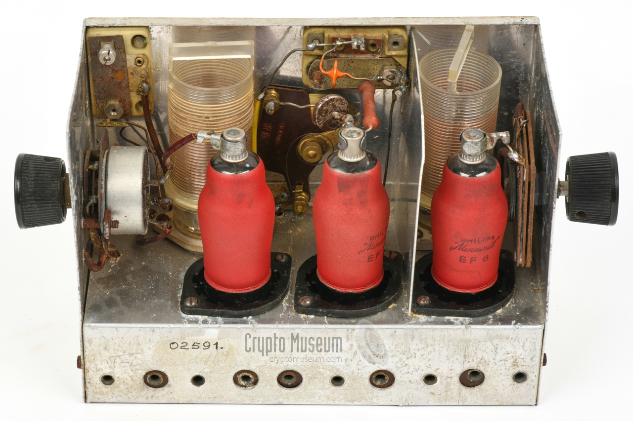
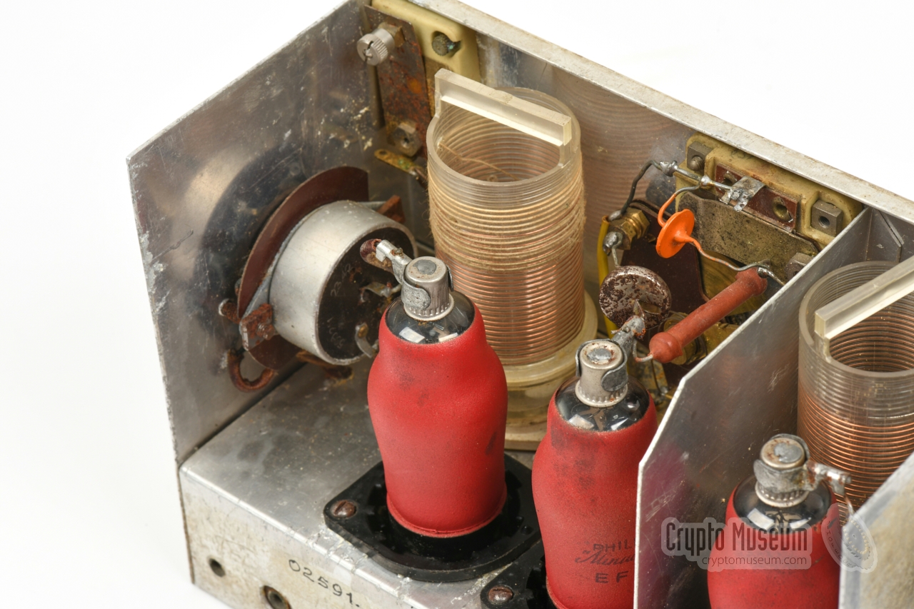
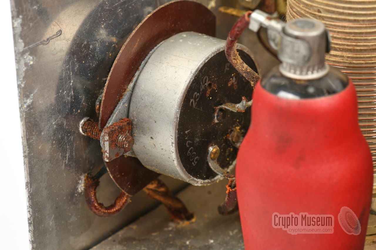
The receiver is built around three identical EF6 valves.
The one at the right is used as an RF
pre-amplifier. It has a removable antenna coil
and a tuning capacitor that is accessible from the side.
The antenna/ground sockets are right below it.
|
|
|
|
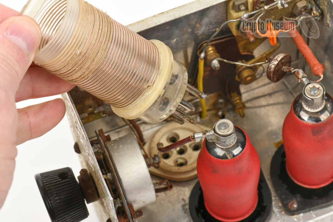
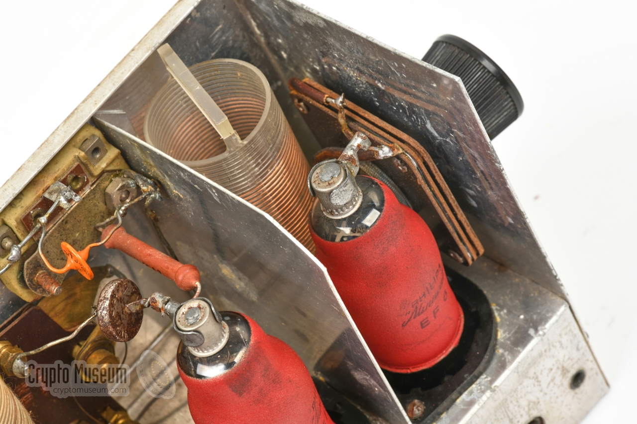
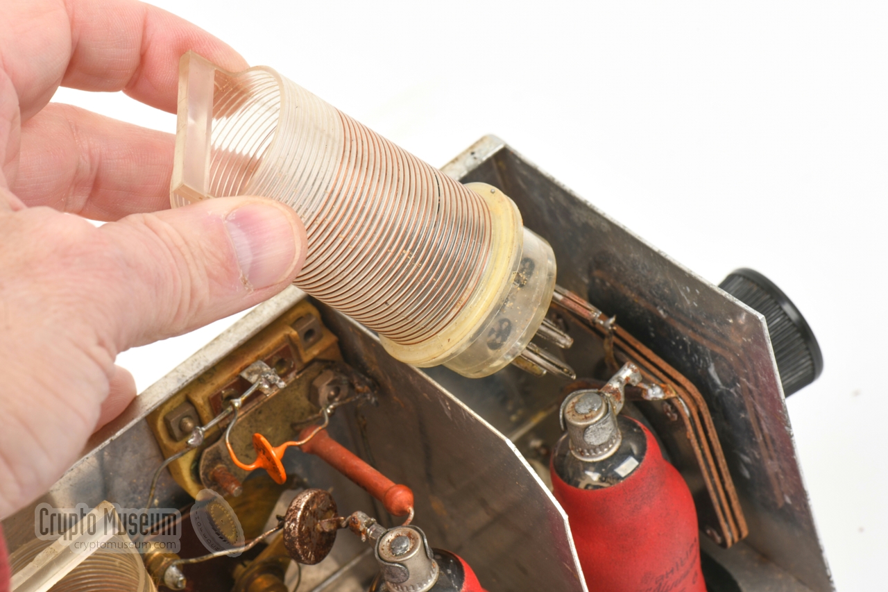
At the center is the oscillator/detector valve. Like the RF pre-amplifier
it has a removable coil,
that can be swapped to make the receiver suitable for
the reception of the 31, 41 and 49 metre broadcast bands.
Unfortunately, the additional coils are missing from the device shown here.
|
The oscillator is tuned with the adjustable capacitor at the front panel.
It has fixed and
adjustable capacitors connected in parallel,
so that the
centre of the frequency range can be adjusted as required. Furthermore, the
feedback loop (reaction) can be adjusted with a trimmer that is
fitted in the left corner of the front panel.
The leftmost valve is used as an AF amplifier. Via the potentiometer
in the side panel, it is fed with the signal from the detector stage, which is
then amplified to a level that is suitable for a high-impedance pair of
headphones (4000-5000 Ω).
|
|
|
|
The sockets for the headphones are at the far left. Note that there is
no isolation transformer present in the output stage. The headphones are
directly connected to the anode voltage of the AF amplifier valve
(via a 25 nF capacitor) so it is strongly advised to use properly isolated
phones.
|
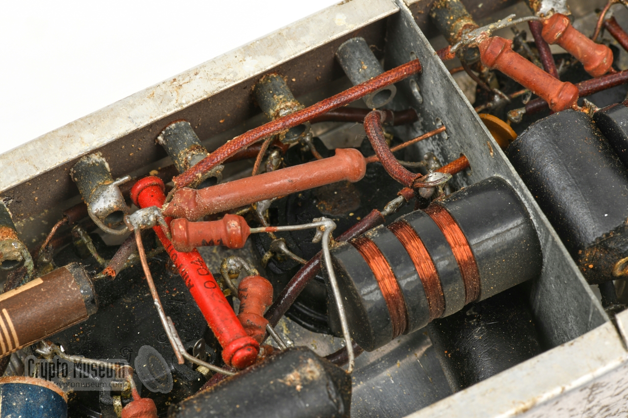
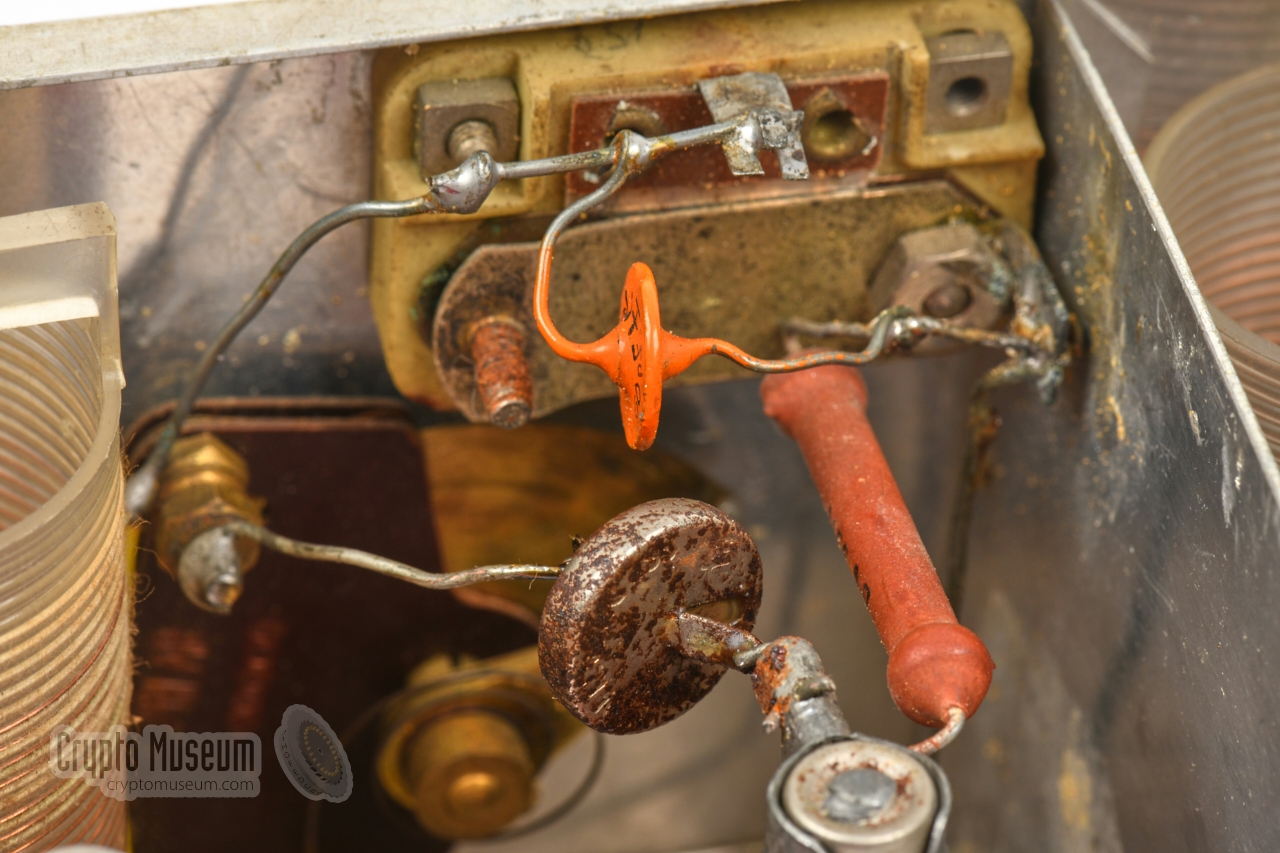
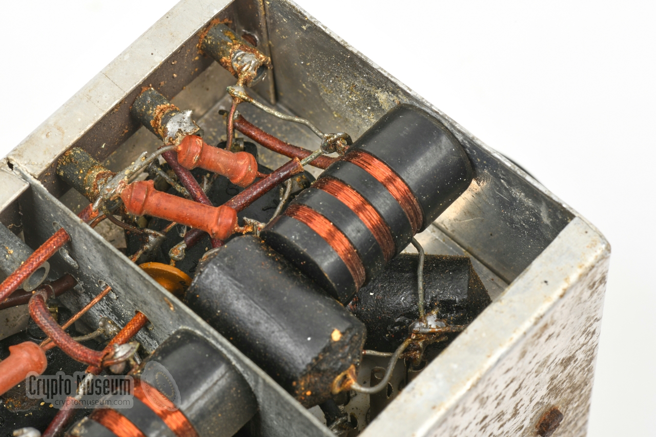
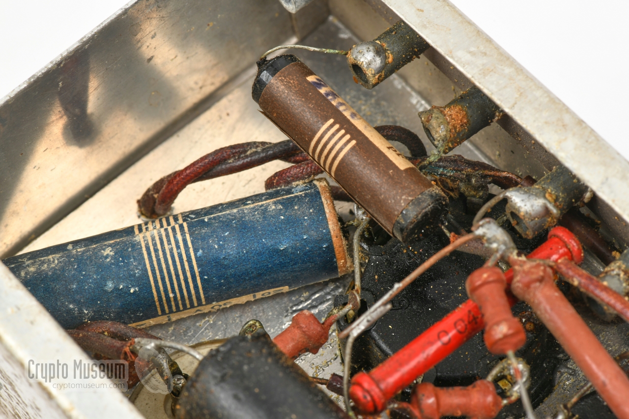
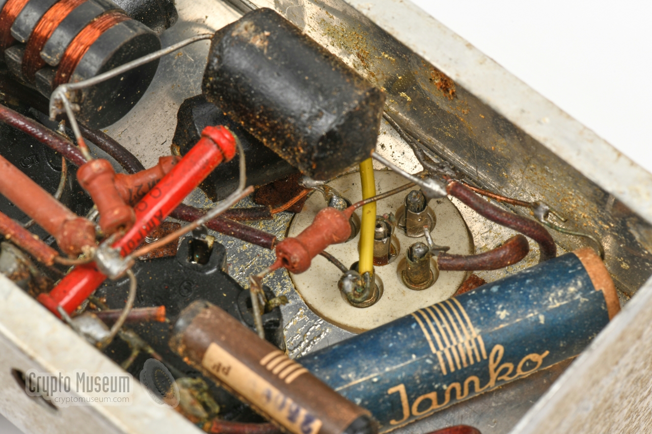
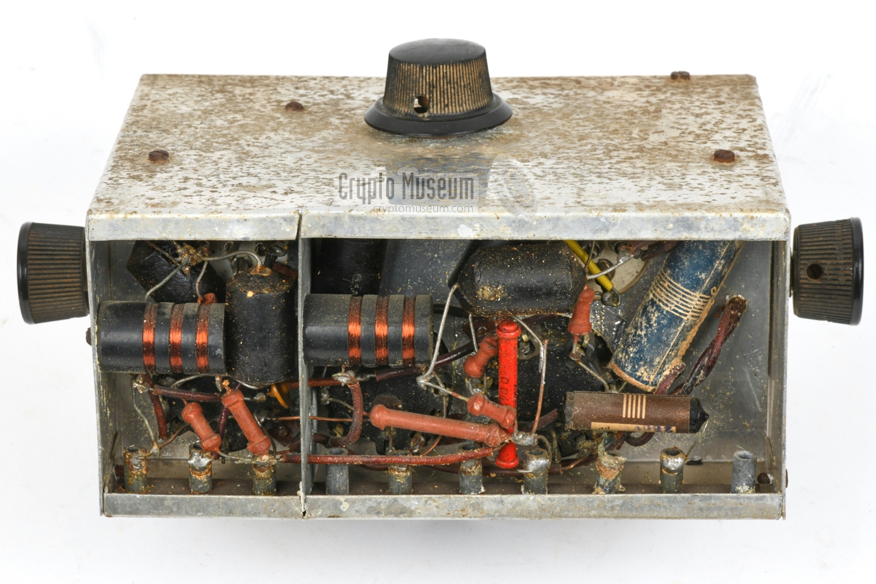
The bottom section of the chassis
holds most of the passive components,
such as resistors, capacitors and choke coils. Like the
top section of
the chassis, is has two compartments: one for the RF amplifier, and
one for the remaining part.
The first two valves (V1, V2) have a choke coil in their anode rail.
These coils are mounted to the side panels as shown in the image on
the right.
This image also shows the point where the HT voltage from one of the
sockets, is distributed throughout the device via a network of resistors.
|
|
|
|
The device is powered by two voltages which have a common ground: +6.3V for the
filaments of the valves (LT), and +250V for the anodes (HT). This
relatively high HT voltage is chosen to allow the same power supply unit
(PSU) to be used as for the OD Transmitter.
0V goes to the chassis.
|
When we acquired our OD Receiver in November 2020 [1], it was uncertain
whether it would ever work again. Although it should not be too difficult
to bring the simple circuit back to life again, this might involve swapping
certain components for modern alternatives. Given the unique nature of the
device however, we wanted to keep it in its original wartime condition as much
as possible.
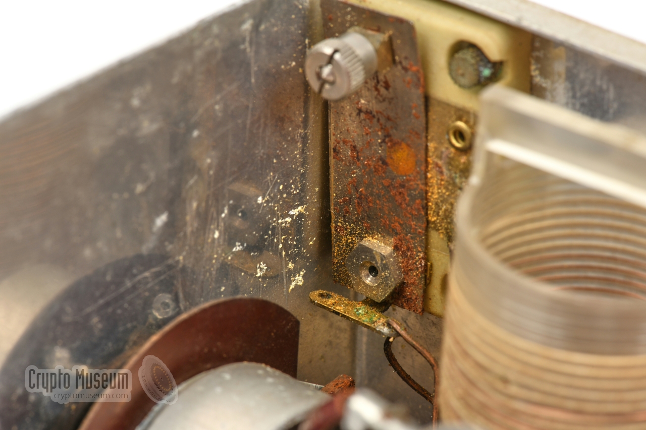
A first visual inspection revealed that the device shows severe signs of
corrosion. This is partly caused by the poor quality aluminium that was
available during the war, but also by the conditions under which it was
stored after the war. The corrosion is most serious at the points where
two different types of metal are in contact with each other.
This is known as galvanic corrosion.
After carefully removing the most serious corrosion, some wires that had
loosened over time, were re-soldered. This was partly caused by
the corrosion, but also by the fact that the antenna tuning capacitor was
not properly fixated to the side panel, as a result of which the leads
and the first valve (V1) moved when the knob was turned. Next, the valves
and the plug-in coils were removed, so that the values
of all resistors and capacitors could be checked with an LCR meter.
When we were satisfied that all values were still within their specified
range, the valve sockets were cleaned and the valves were re-seated.
The +6.3V LT voltage for the filaments of the valves was connected,
and the power switch was turned ON. After the current had stabilised
at ~ 560 mA (which is reasonable for three EF6 valves), the +250V
HT voltage was applied. Noise was heared through the headphones,
and the 3 MHz signal from an external generator was quickly
picked up. The OD Receiver still works after more than
75 years, with its original components!
So far, the following restorations have been carried out:
|
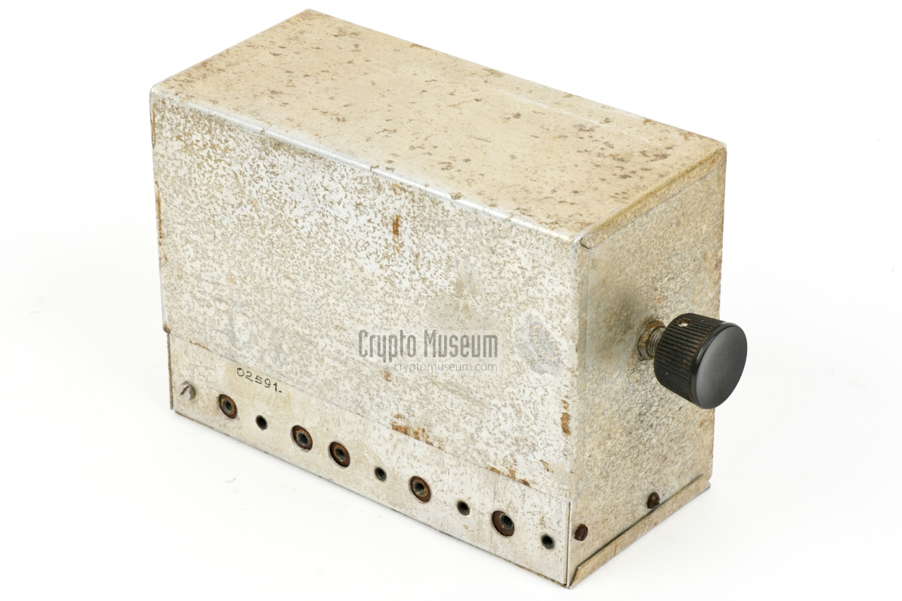
All connections of the OD Receiver are at the rear.
Below is the layout of the sockets, as seen from the
rear of the device.
All sockets accept short 4 mm banana plugs, 1 and are fitted on
a pertinax 2 strip.
Note that the sockets where a brown pertinax ring is visible,
are isolated and carry signals or live voltages.
All other sockets are mechanically attached to the chassis (ground).
Note that we have modified the socket at the far left, by
fitting a 4 mm screw right through it.
The screw is held in place with a nut on the inside of the chassis.
This is done to keep the pertinax strip in place when inserting banana plugs
into the other sockets, and reduces the risk of breaking the pertinax strip.
In our case, the leftmost socket was detached due to corrosion.
|
-
The sockets are only 10 mm deep. Inserting regular 4 mm banana plugs
with a length of 20 mm, all the way in, may damage the components in the
bottom section of the receiver, or may cause a short-circuit.
-
Also known as resopal.
|
EF6 is a universal penthode, developed specifically for AF applications.
According to the datasheet it is unsuitable for
application in RF and IF amplifiers. Nevertheless it was used in all stages of the OD Receiver, probably because no other valves were
available at the time.
Below is the pinout of the EF6, as seen from the bottom of the valve (i.e. the
solder side of the socket).
➤ EF6 datasheet
|
Design Philips, Jan Thijssen Manufacturer Philips, Jan Hendrik (Henk) Op den Velde (Zaandam) User Binnenlandse Radiodienst (BR) of the Ordedienst (OD) Introduction 1942 Frequency 2.85 - 3.15 MHz (variations are known) Antenna Long-wire Circuits RF pre-amplifier, detector, AF amplifier Valves 3 x EF6 Power LT +6.3V, HT +250V Dimensions 200 x 140 x 100 mm Weight 1100 grams Accessories Power Supply Unit (PSU), Headphones
|
Design Jan Lourens Manufacturer Jan Lourens (Oosterbeek), Piet Neve (Zeeland) User Binnenlandse Radiodienst (BR) of the Ordedienst (OD) Frequency 2.95 - 3.25 MHz (adjustable) Antenna Long-wire Circuits RF pre-amplifier, detector, AF amplifier Valves 3 x EF6 Power LT +6.3V, HT +250V Dimensions 240 x 135 x 110 mm (bare case: 185 x 135 x 90 mm) Weight 922 grams Accessories Power Supply Unit (PSU), Headphones
|
- Cor Moerman, OD Receiver - THANKS !
Received November 2020.
- Crypto Museum, Internal research of OD Receiver in collection
CM303549. December 2020.
- Louis Meulstee, Wireless for the Warrior, volume 4
ISBN 0952063-36-0, September 2004
- Jan Schulten, De radiopost van de Ordedienst in Rijsbergen
- achtergronden van het drama op de Vloeiweide - (in Dutch language).
Jaarboek De Oranjeboom 47, 1994.
- A.S.M. van Schendel, Mijn werkzaamheden als chef-marconist van de OD en mijn belevenissen in de gevangenis
Organisation of the Interal Radio Service (BR) of the OD
and the radio links with the UK.
Post-war report, in Dutch language. Date unknown.
- Wikipedia (Netherlands), Henk op den Velde
Retrieved December 2020.
- Medica Amsterdam, Luxor - Bestralingsapparaat
1938. In Dutch language. CM301583/3/5.
- D.W. (Dick) Rollema (PA0SE), Radioverbindingen van het Verzet in Zeeland
VERON Electron, May 1987
- D.W. (Dick) Rollema (PA0SE), Station G11 van de Binnenlandse Radiodienst
VERON Electron, May 1988
|
|
|
|
Any links shown in red are currently unavailable.
If you like the information on this website, why not make a donation?
© Crypto Museum. Last changed: Sunday, 17 August 2025 - 10:47 CET.
|
|

|
|
|


![OD radio station of Region 6 (Apeldoorn). Photograph kindly provided by Louis Meulstee [3].](img/OD_RX1_large.jpg)
![OD radio station of Region 11 in Zaandam in April 1945. Photograph kindly provided by Louis Meulstee [3].](img/OD_set1_large.jpg)
![OD radio station of Region 11 in Alkmaar in late 1944. Photograph kindly provided by Louis Meulstee [3].](img/OD11_hospital_large.jpg)
![OD radio station of Region 15 in Grijpskerke in 1944. Photograph kindly provided by Louis Meulstee [3].](img/OD_set2_large.jpg)


