|
|
|
|
|

|
|
WWII OD OD Set →
The device is housed in an aluminium enclosure that measures 114 x 114 x 55 mm.
A 110 mm long wooden grip at the bottom, allows it to be held in the hand
without touching the metal.
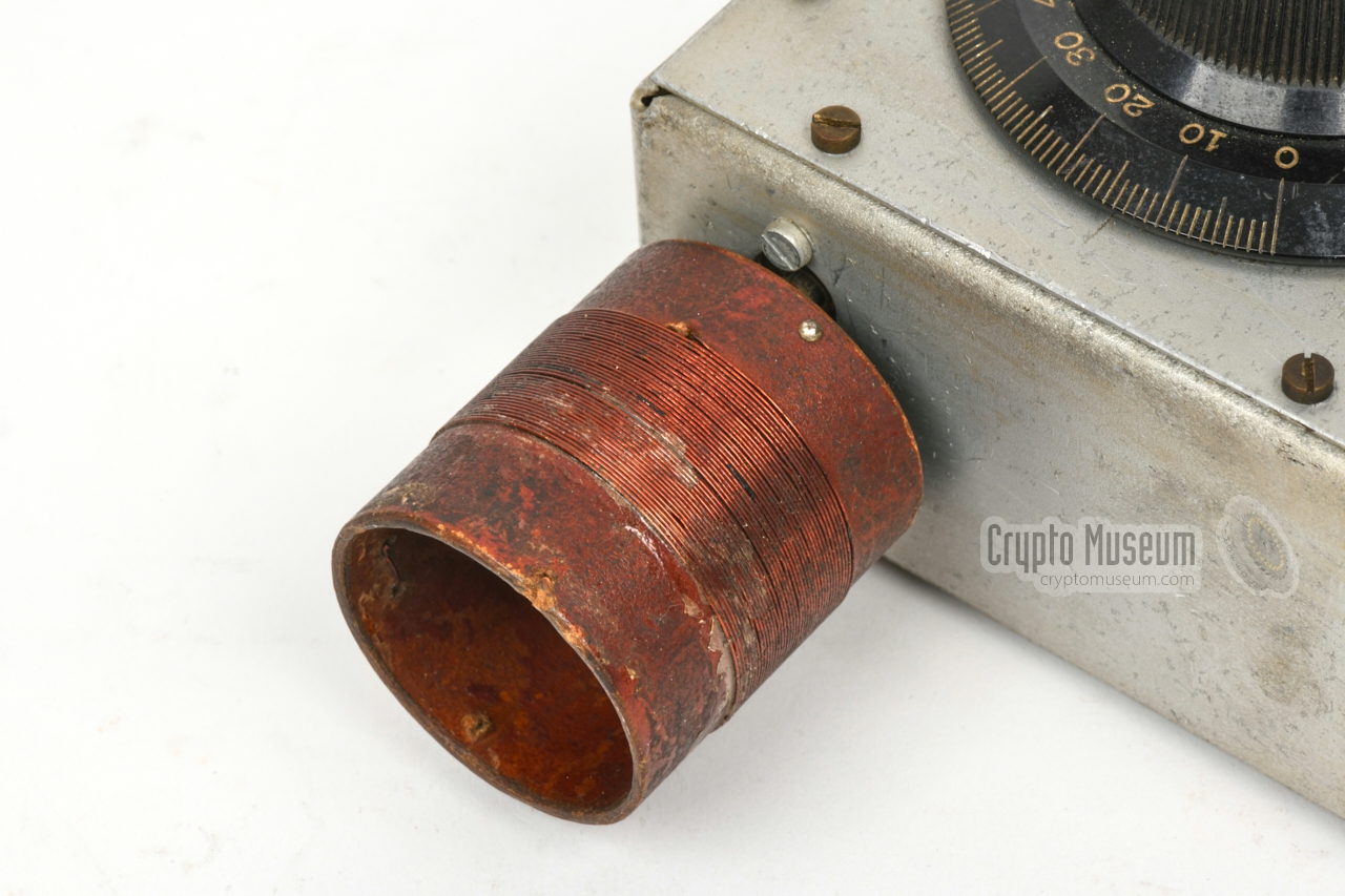
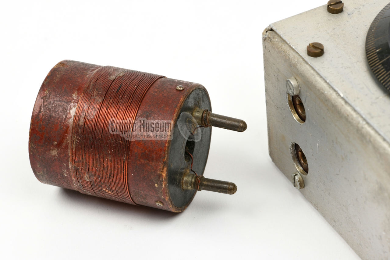
At the top is a removable coil that is
installed into a two-pin socket of which the pins are 19 mm apart. The coil
is 40 mm wide and extends from the top of the device by approx. 50 mm.
At the front panel is a large circular bakelite knurled knob, of which one half
(i.e. 180°) carries a linear scale, marked from 0 to 100.
|
|
|
|
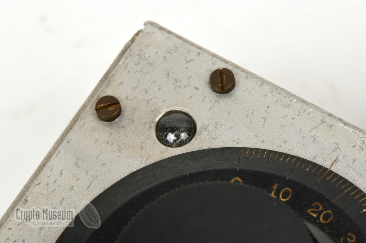
In the upper left corner is a neon lamp
that protrudes the front panel.
It acts as a power indicator, and lights up brighter when
more power is absorbed by the instrument.
With the wooden grip, the bakelite knob and the coil, the device
measures 274 x 114 x 87 mm and weighs 460 grams.
|
The image below gives an overview of the features of the OD Wavemeter.
It should be held by the wooden grip – which is similar to the grip of, say,
a screwdriver of the era – so that the aluminium enclosure is left untouched.
Next, the black frequency dial is set to the desired frequency,
using a separately supplied calibration chart (missing here).
This is done by looking up the frequency and finding the corresponding
linear number.
The dial is then set with this number at the index line.
Next, transmitter is turned on, and the coil of the wavemeter is
brought close to the antenna or to the antenna coil of the transmitter.
The frequency adjustment of the transmitter is now turned until the
indicator (neon lamp) on the wave meter lights up as bright as possible.
If the light is too bright, move the wavemeter away from the transmitter
and try again. When the maximum is found, the frequency of the transmitter
matches that of the tuned circuit inside the wavemeter.
|
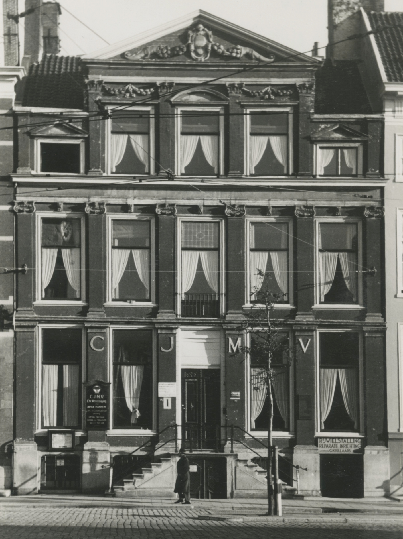
The CJMV building – shown in the 1943 image on the right [5] –
was selected because of its strategic position.
The radio station was located in the attic, whilst the windows
at the top floor offered a good view of three surrounding
streets: Prinsegracht, the corner with Boekhorststraat and, opposite
the front door, Jan Hendrikstraat.
The building was also chosen because of the presence of electric
overhead lines of the tram. It was assumed that these lines would cause
interference when the Germans tried to locate the transmitter by means of
radio direction finding.
The transmitter was usually operated by wireless operators Adri van Mansum
(of Delft) and Joop Ketting (of The Hague), and occasionally also by
Dick Reijns, who had been appointed by wireless coordinator
Anton van Schendel
as the radio officer of OD Region 13
[3].
Reijns was a radio amateur (PA0RS) and had
a radio repair shop at Jan Hendrikstraat, close to the CJMV building.
He was responsible for the contact with London,
as well as for the contact with
other OD regions,
via the secret national OD communications network.
|
|
|
Close to the end of the war – on 18 February 1945 – during communication
with the OD post in Eindhoven
(Region 18) 1
Reijns and van Mansum were
arrested by the German Sicherheitsdienst (SD) [3].
They were executed less then three weeks later, on 8 March 1945 at Waalsdorpervlakte [6].
Joop Ketting and Anton van Schendel
both survived the war.
The wavemeter
featured on this page and a morse key made by NSF,
are the only remains of the OD radio post in The Hague [1].
➤ Further history of the OD equipment
|
-
Eindhoven was already liberated at this point.
|
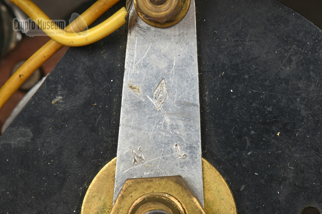
Below is the circuit diagram of the OD Wavemeter [7].
It is basically a simple
tuned circuit, that consists of a coil (L) and a variable capacitor (C)
connected in parallel to a neon lamp (La). The resonance frequency of the tuned
circuit (f0) is calculated with the formula at the right.
The coil (L) is mounted outside the enclosure, so that it can absorb some
energy from the transmitter.
When the resonance frequency of the tuned circuit is the same as the frequency
emitted by the transmitter, the tuned circuit absorbs the maximum amount of
energy, which is then fed to the (high-impedance) neon lamp. The device is
fully passive, which means that it does not require an external power source,
such as a battery, for its operation. It is driven by the absorbed energy.
|
|
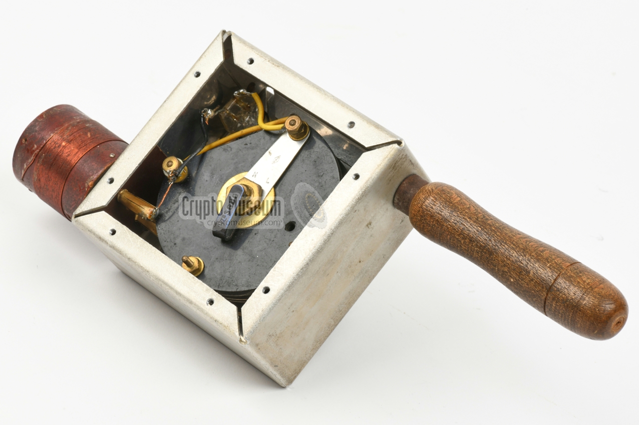
The interior of the OD Wavemeter can be accessed by removing the eight screws
along the edges of the rear panel, after which the rear panel can be taken off,
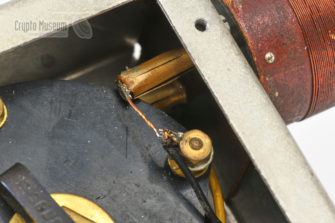
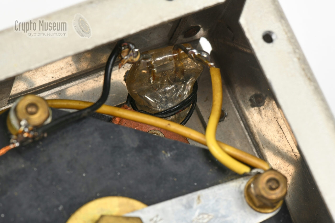
as shown in the image above. Inside the enclosure are just to components: (1)
a large variable capacitor (the black disc at the centre) and a regular
neon lamp mounted in the upper corner.
A socket for the coil is in the other corner.
|
|
|
|
Any links shown in red are currently unavailable.
If you like the information on this website, why not make a donation?
© Crypto Museum. Created: Tuesday 29 December 2020. Last changed: Wednesday, 05 November 2025 - 12:08 CET.
|
 |

|
|
|