|
|
|
|
|

|
|
Crypto AG Voice BND CIA CRYPTOCOM →
The basic device measures 256 x 225 x 78 mm and weighs 4.2 kg
(when the optional AC
PSU is installed).
All connections are via a standard 37-pin D-sub
socket (DC37/M) at the rear, or via a pre-wired cradle. The device
is controlled via a detached remote control unit that consists of
a keypad, a LED display and a mechanical lock.
The HC-250 can be powered from a 12V or 24V DC source, such as the battery
of a car or truck. When the optional AC
PSU is fitted, it can also be powered
from the 110V/220V AC mains.
There was also a portable variant in a regular briefcase.
|
|
|
|
The HC-250 and its predecessor
– the HC-210 –
were intended as replacements
for the bulky CRM-008, also known as
HC-230 and
HC-235.
It offers excellent audio quality, with full speaker recognition and no
residual intelligible audio on the line. This is achieved by scrambling in
the time domain as well as in the frequency domain. This principle is also
known as F/T scrambling
or two-dimensional scrambling.
Nevertheless, all
speech scramblers are inherently insecure.
|
- HC-250
Civil version for vehicle mounting or desktop use, with a detached
control panel. When used in a vehicle, the front panel is usually mounted
on the dashboard. The device featured here, is of this type.
This version was also available in a briefcase variant.
- HC-255
Military version in ruggedised green die-cast aluminium enclosure.
(MIL-STD-810).
This version has the control panel at the front.
It is shown in the 1992 company brochure
[1].
|
The HC-250 was developed at a time when
Crypto AG
was owned by the German
Bundesnachrichtendienst (BND)
and the American
Central Intelligence Agency (CIA). There are
two versions of the cryptologic: one that was secure, and one that
was readable 1 by NSA
and ZfCh codebreakers.
From the mechanical construction, the PCB layouts and the choice of
components, such as the Motorola 68000 processor [a] and the
MC14404 CODECs [c], it seems likely that the
HC-250 was developed by the Government Electronic Division of
Motorala
in Phoenix (Arizona, USA).
At the time, Motorola
was a subcontractor of Crypto AG
(just like Siemens),
influenced by the NSA.
|
|
So far, the following users have been confirmed:
|
In 1984, the intelligence service of the DDR (East-Germany) —
Ministerium für Staatssicherheit (MfS),
also known as the Stasi — obtained two working
HC-250 units from Cuba. The processor section of the device was analysed by a
technical student who wrote a thesis on it [4],
after which the devices were passed on to the Russian partner
– KGB –
for further research and analysis [2].
Apparently the Russians did not try to break any HC-250 traffic, as only Libya
was known as a user at the time. The device was nevertheless found to be of
interest, as it reflected the current state-of-the-art in the Western world.
The Russians wanted to use the technology in their own devices,
and asked Stasi
to find additional technical documentation from Western sources [2].
|
-
In this context, readable means that the cryptographic algorithm
could be broken by NSA
and ZfCh.
Also known as friendly. In contrast:
algorithms that are not breakable,
are called unfriendly or unreadable [3].
|
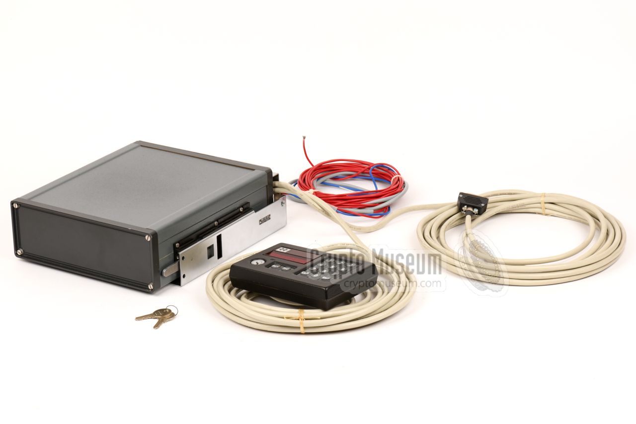
The actual encryptor measures 256 x 225 x 78 mm and weighs 4.2 kg (with the
AC power supply unit present). It is usually mounted in a
pre-wired cradle
and is locked in place by two spring-loaded levers at the sides.
At the rear is a 37-pin male socket (DC37/M) that provides the connections to
the (car) battery, the remote control unit,
and a telephone or radio interface. In the unit featured here, the (optional)
mains PSU is also present. It allows the unit to be powered from the 220V or
110V AC mains (switch-selectable).
|
|
|
|
|
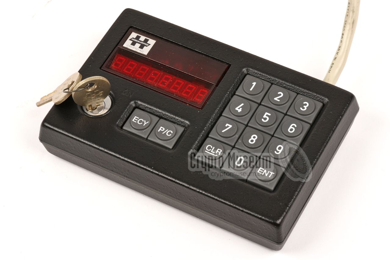
Remote control unit
ATC-250
|
|
|
All unser controls are on the external rempte control unit, shown in the
image on the right. It was connected to the cradle, which in turn
is connected to the HC-250 encryptor.
It has a 12-button keypad, two buttons for selecting the desired mode of
operation, a key-lock – for entering the BASIC key – and an 8-digit numeric
red LED display.
|
|
|
For mobile use, the HC-250 was generally mounted in the purpose-made cradle
shown in the image on the right. It has three fixed cables: for a 12V (car)
battery, for connection to the telephone or radio interface, and to the
remote control unit.
All connections to and from the HC-250, with exception of the mains power
cord, are via the 37-pin male socket (DC37/M) at the rear of the device.
It mates with the DC-37/F socket at the rear end of the cradle.
|
|
|
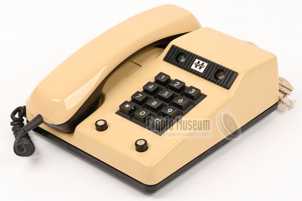
For full-duplex use, the TFC-250 desktop telephone set was connected to
the HC-250. It is a regular telephone set – manufactured by Telefonbau und
Normalzeit (T&N) in Germany – that is modified for use with the voice encryptor.
The telephone set has two buttons for selecting between plain(P)
and crypto (C),
plus two LED indicators behind the numeric keypad.
The green LED signals that secure speech is used.
Note that they * and # keys are blocked.
|
|
|
Each device came with a full user manual with operating instructions,
and directions for its installation. It also describes the use of the
various types of cryptographic keys.
In addition there was an installation manual, in which details of the
wirings and (optional) settings are provided.
➤ Download user manual
➤ Download installation manual
➤ Download technical drawings
|
|
|
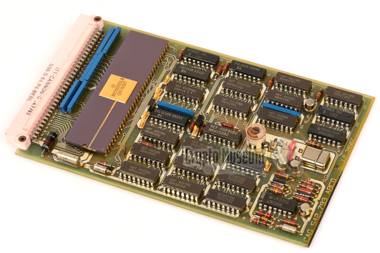
The block diagram shows the different functional blocks of the HC-250
and how they are interconnected. Four cards are connected to the processor
bus: The processor board
– that holds the Motorola 68000 processor, the
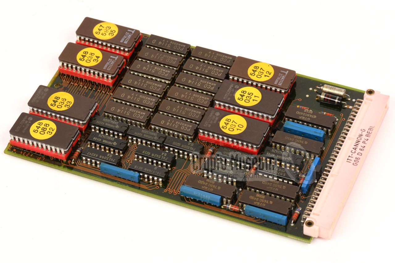
memory board
– that holds the RAM and the firmware in EPROM – the
interface
to the remote control unit, which also holds the
static key memory (SRAM) with a Lithium backup battery, and the
CODEC board which holds two sets
of D/A and A/D converters.
The remaining boards hold the analogue parts. The
Universal Interface Board
(here shown at the top), maintains the physical connection to the telephone
line and the handset — commonly via a modified telephone set.
When the device is used in combination with a 2-way (mobile) radio,
e.g. police or other public service,
the universal interface is replaced by a Half-Duplex Interface.
|
|
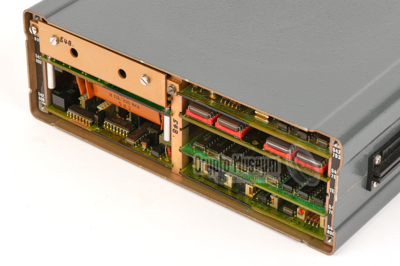
The interior of the HC-250 can be accessed via the (blind) front panel.
It requires removing the four screws in the corners of the front panel,
and taking the entire front off.
This reveals 7 eurocard size (16x10 cm)
printed circuit boards (PCBs) that are held in place by a slotted metal
frame.
|
|
The power board
contains a switched-mode power supply unit (PSU) that
can be operated from 9 to 30 V DC, making it
ideal for use in a car (12V) or truck (24V). If the device should
be powered from the AC mains, an (optional) mains transformer can be
installed behind the rear panel.
|
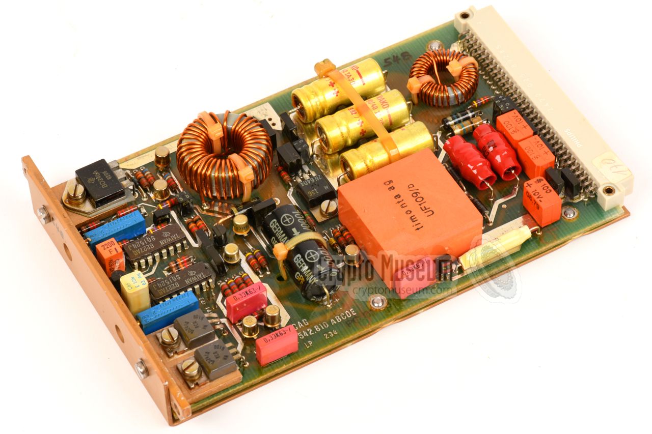
The filter board
— that connects the
interface board to
the CODEC board
— holds a lot of proprietary (custom-made) components,
as shown in the image on the right. The orange parts are ceramic
substrates with the filters and amplifiers, covered by a
water repellent coating.
According to the date codes on the substrates, they were
manufactured in week 23 of 1981. In addition, there are other
OEM parts, such as the
integrated circuits (ICs) with the golden caps.
These may be early (pre)production samples, or
custom-chips that were not generally available.
|
|
|
|
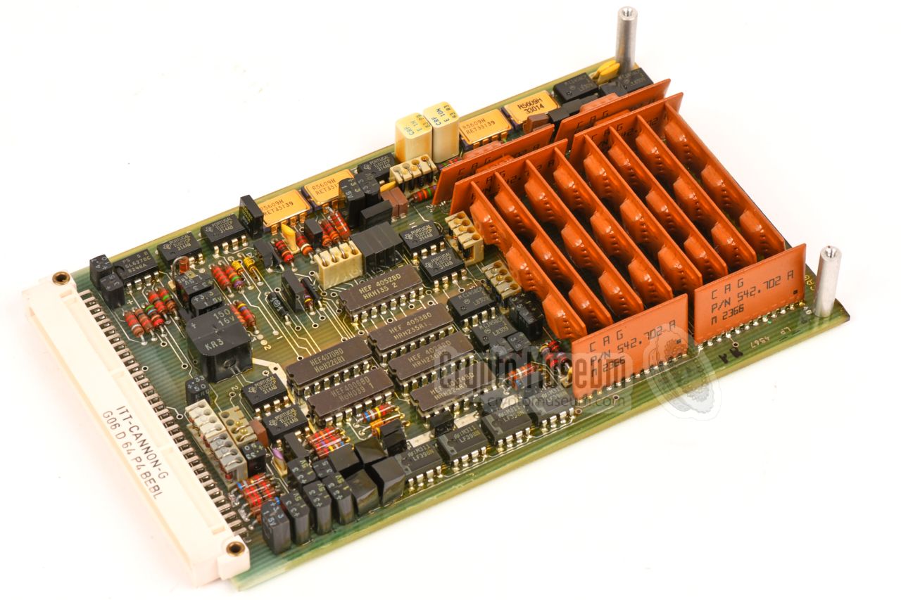
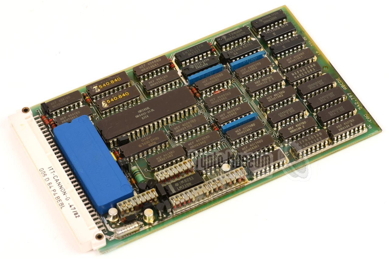
The interface board
for the remote control unit,
contains an Intersil IM6402 UART – for a two-way RS232 serial connection
with the remote control unit – quite a lot of digital circuits,
and the static random access memory (SRAM) that is used for storing the
user-programmable cryptographic keys. The keys are retained by an on-board
long-life Lithium battery (the large blue rectangle). 1
|
-
Note that by now, such batteries are exhausted and may start leaking.
even though they are sealed.
It is advised to remove them as soon as possible, to avoid permanent
damage to the PCBs.
|
- +7.5V
- 5.2V
- Ground
- Ground
- /EMCY
- KSC
- /ADTE
- RX
- TX(0)
- PTT
- R/T
- AUX IN(0)
- LACT
- T/R TX
- AUX 2
- AUX 4
- AFR(0)
- AFT(0)
- DC(+)
- -7.5V
- 0V
- ADCLR
- ADR
- 5VSB
- ADT
- RX(0)
- TX
- PTT(0)
- R/T(0)
- AUX 1
- LACT(0)
- AUX IN
- AUX 3
- not used
- AFR
- AFT
- DC(0)
|
|
Point-to-point 2.3 sec. Multipoint 1 sec Tracking Continuous Interrupt 1000 sec. max. (100 sec. over full temperature range) Delay 314 ms, or 130 ms (Duplex Comfort) Signalling 1302/1736 Hz, or 1085/1519 Hz, or 1519/1953 Hz
|
Customer 1027 combinations (PROM) Structure 10308 combinations (EPROM) customer programmable Traffic keys 8 Key space 1032 combinations for each of the 8 keys Message 6.5 · 104 combinations (automatically generated) User ID Up to 8 digits Key ID Up to 8 digits
|
Input 2 mV — 1.5 V (eff) Output 10 mV — 1.5V (eff) Impedance 300/200 Ω Response 350 — 3000 Hz Mic. power 15 V, 30 mA
|
Input 10 mV — 1.5 V (eff) Output 2 mV — 1.5V (eff) Impedance 300/200 Ω Response 640 — 2880 Hz
|
Bandwidth 600 — 2900 Hz (600 — 2400 Hz reduced voice quality) TX loss < 30dB S/N ratio > 10dB Drift < 100 Hz DC voltage 9 — 30 V AC voltage 110/220 V AC ±20%, 45-65 Hz (switch-selectable) Power 12 W (standby < 100 mW) Temperature -10°C to +60°C (storage: -20°C to +80dgC) EMC CE-03, RE-02, MIL-STD 461B, class A1 Dimensions 256 x 225 x 78 mm Weight 3200 grams (with AC PSU: 4200 grams)
|
Dimensions 152 x 100 x 32 mm Weight 500 grams
|
MDF-100 Mounting kit MDG-100 Gooseneck (for remote control unit) ACP-250 Battery supply cable ACC-123 AC mains cable CAS-250 System interface cable AFC-250 Audio cable RCC-250 Remote control cable TEP-250 Service/Test plug PAH-250 Mounting hardware TED-250 Diagnostic test module
|
-
Full name: Bundesbeauftragte für die Unterlagen des Staatssicherheitsdienstes
der ehemaligen Deutschen Demokratischen Republik
(DDR) —
Federal Commissioner for the Records of the
State Security Service
of the former German Democratic Republic (GDR) —
officially abbreviated to BStU.
|
|
|
|
Any links shown in red are currently unavailable.
If you like the information on this website, why not make a donation?
© Crypto Museum. Created: Tuesday 21 January 2020. Last changed: Wednesday, 05 November 2025 - 11:49 CET.
|
 |

|
|
|