|
|
|
|
|

|
|
← Recorders Covert Yachta →
|
Although officially known as a dictaphone, MEZON was generally used
by the KGB
and the MVD for covert recording
of conversations and wire taps.
It is one of the smallest and most beautiful recorders of the era, and
compares favourably with the
Minifon P-55 (1955)
and Minifon Special (1961),
although the latter was capable of recording up to five hours rather than
just one hour.
The MEZON wire recorder is also featured in Keith Melton's excellent
book Ultimate Spy [3 p.110].
In the late 1980s, MEZON was succeeded by the high-end miniature stereo
tape recorder Yachta.
|
-
In physics, MEZON (English: Meson) is a subatomic particle, intermediate
in mass between an electron and a proton, that transmits the strong
interaction binding nucleons together.
|
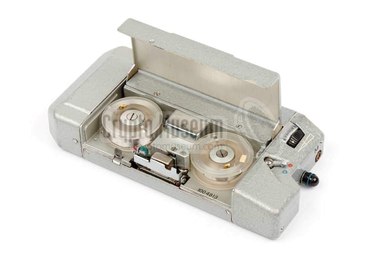
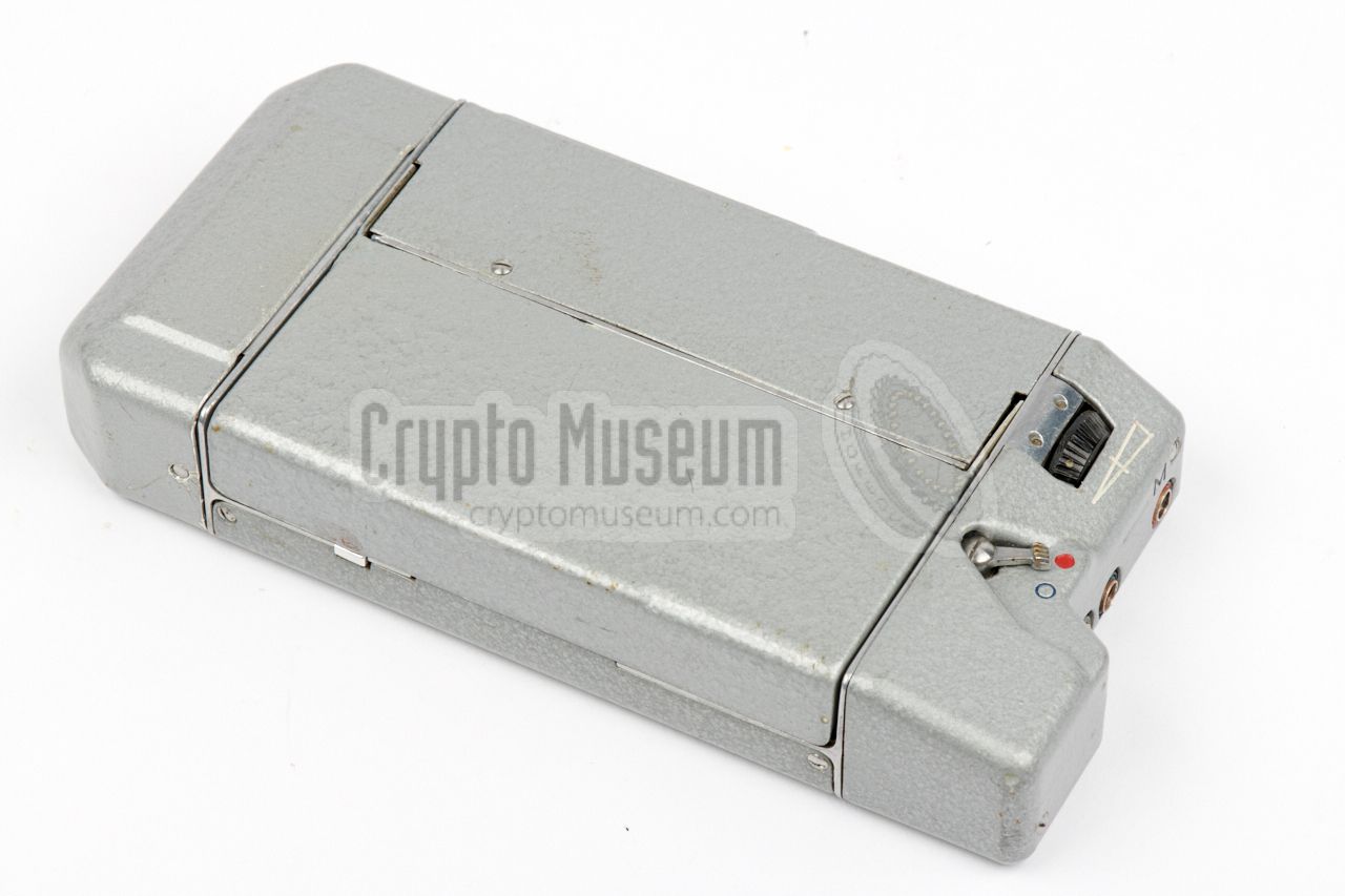
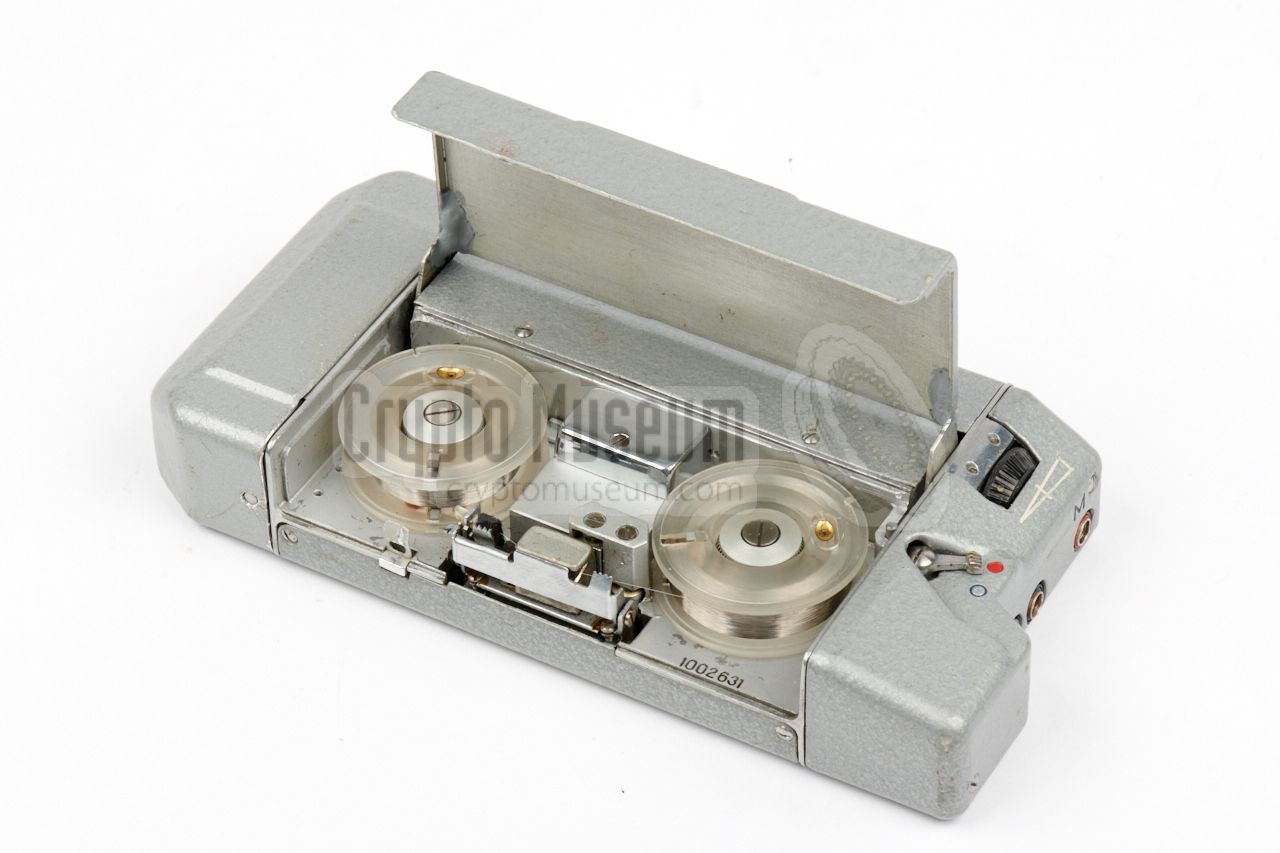
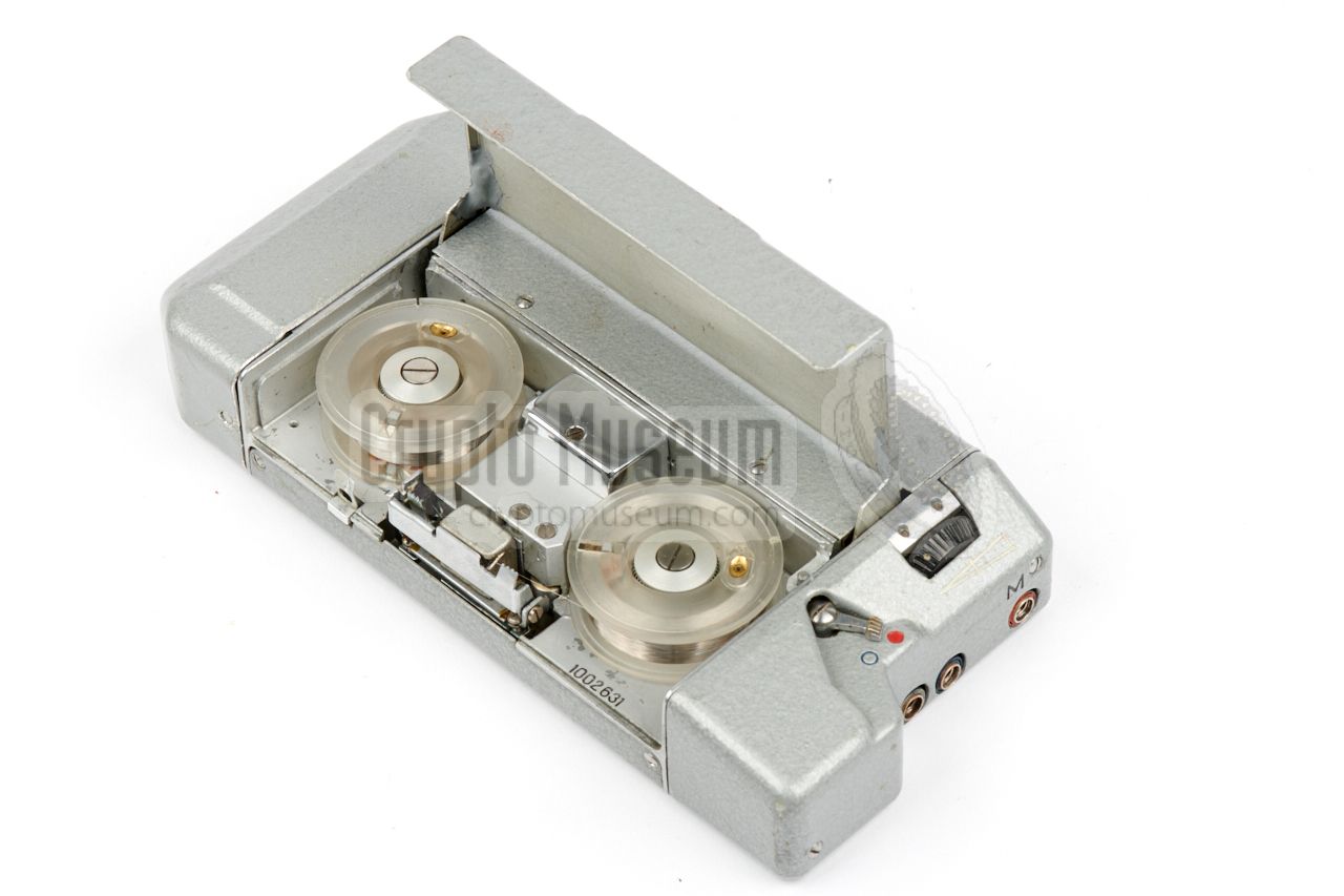
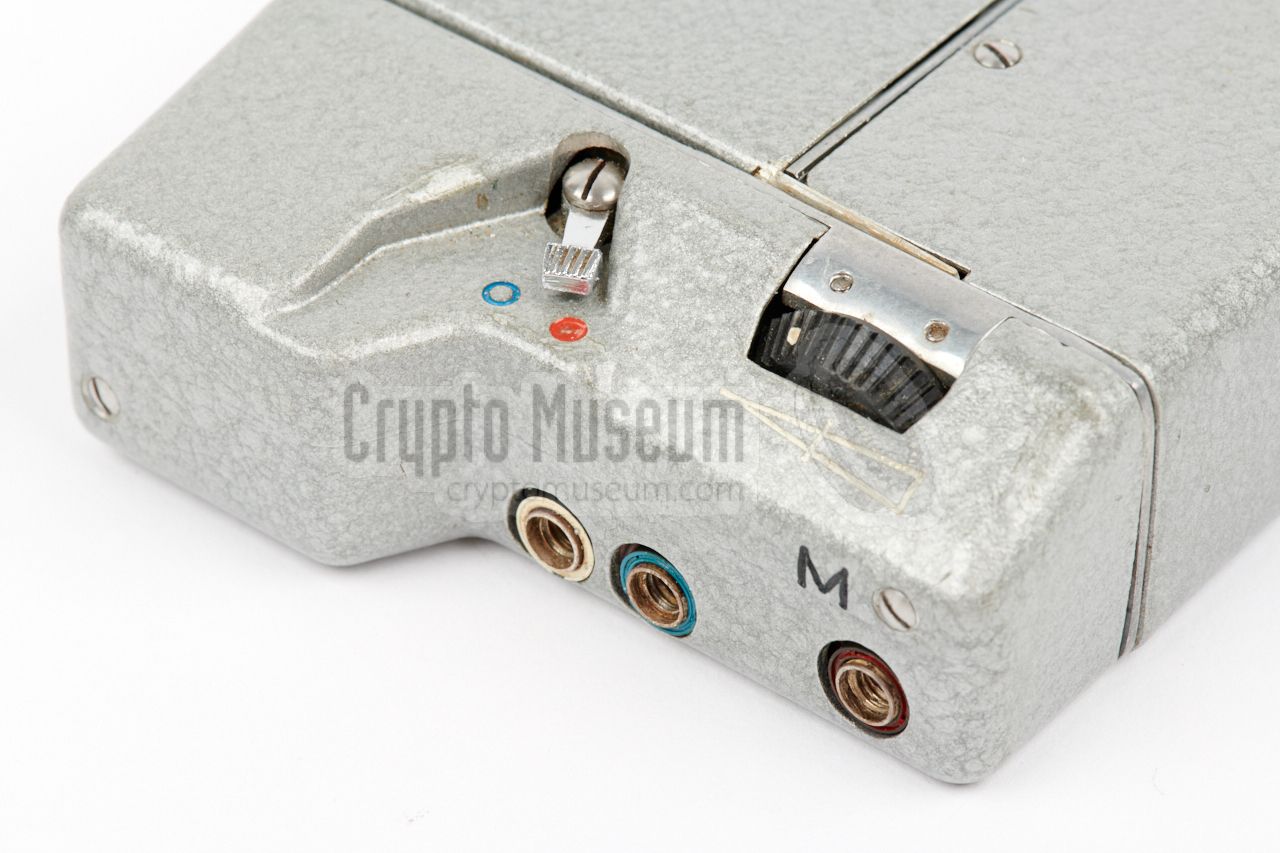
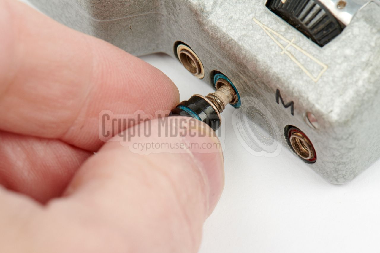
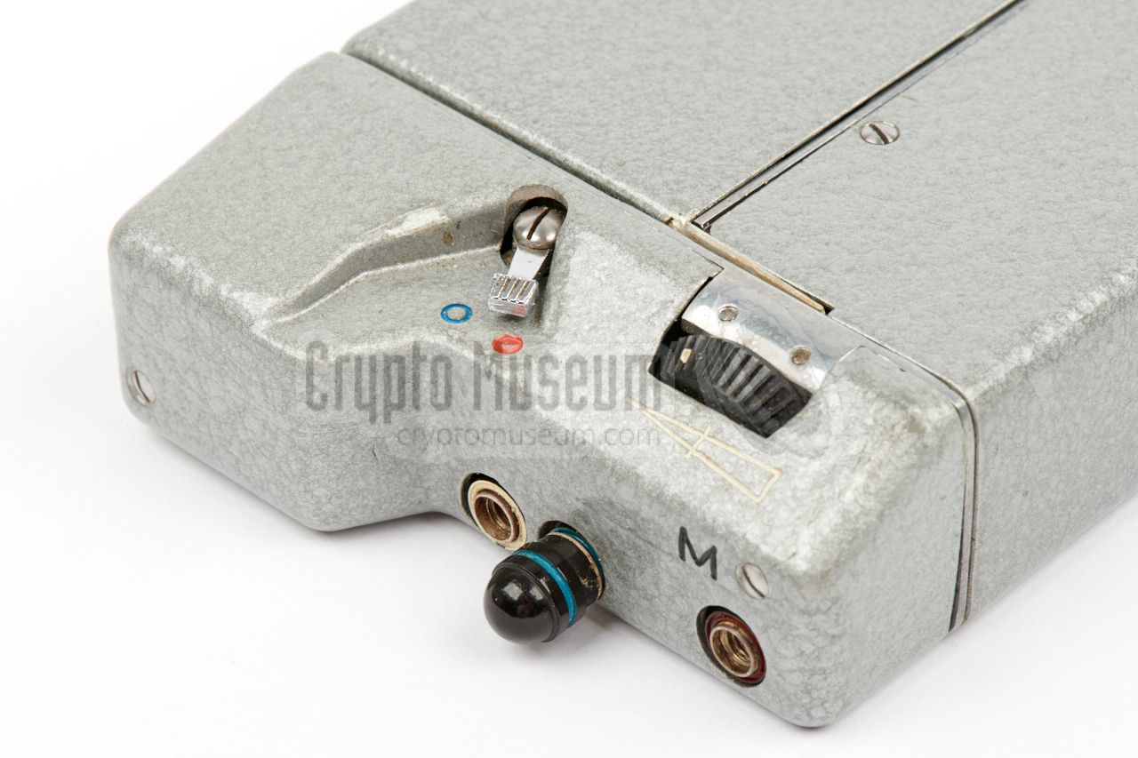
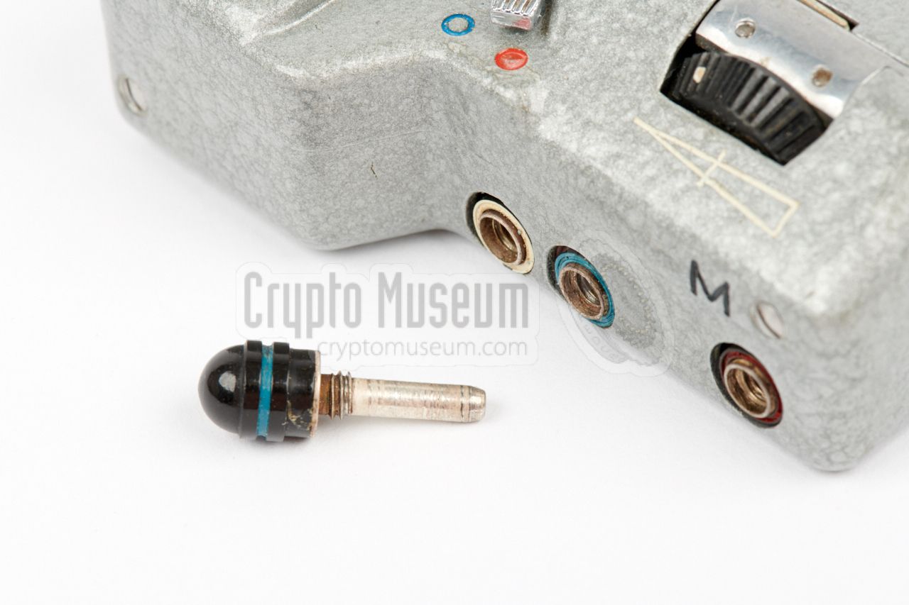
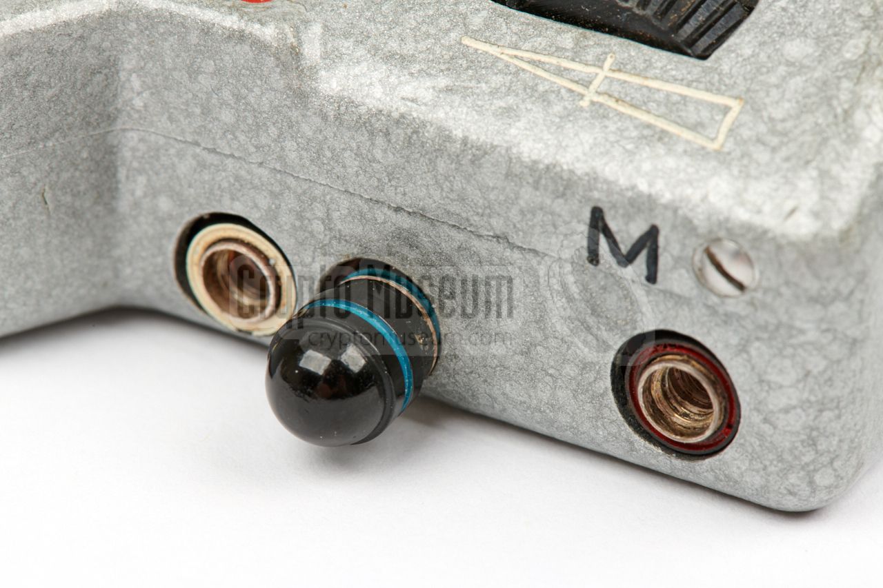
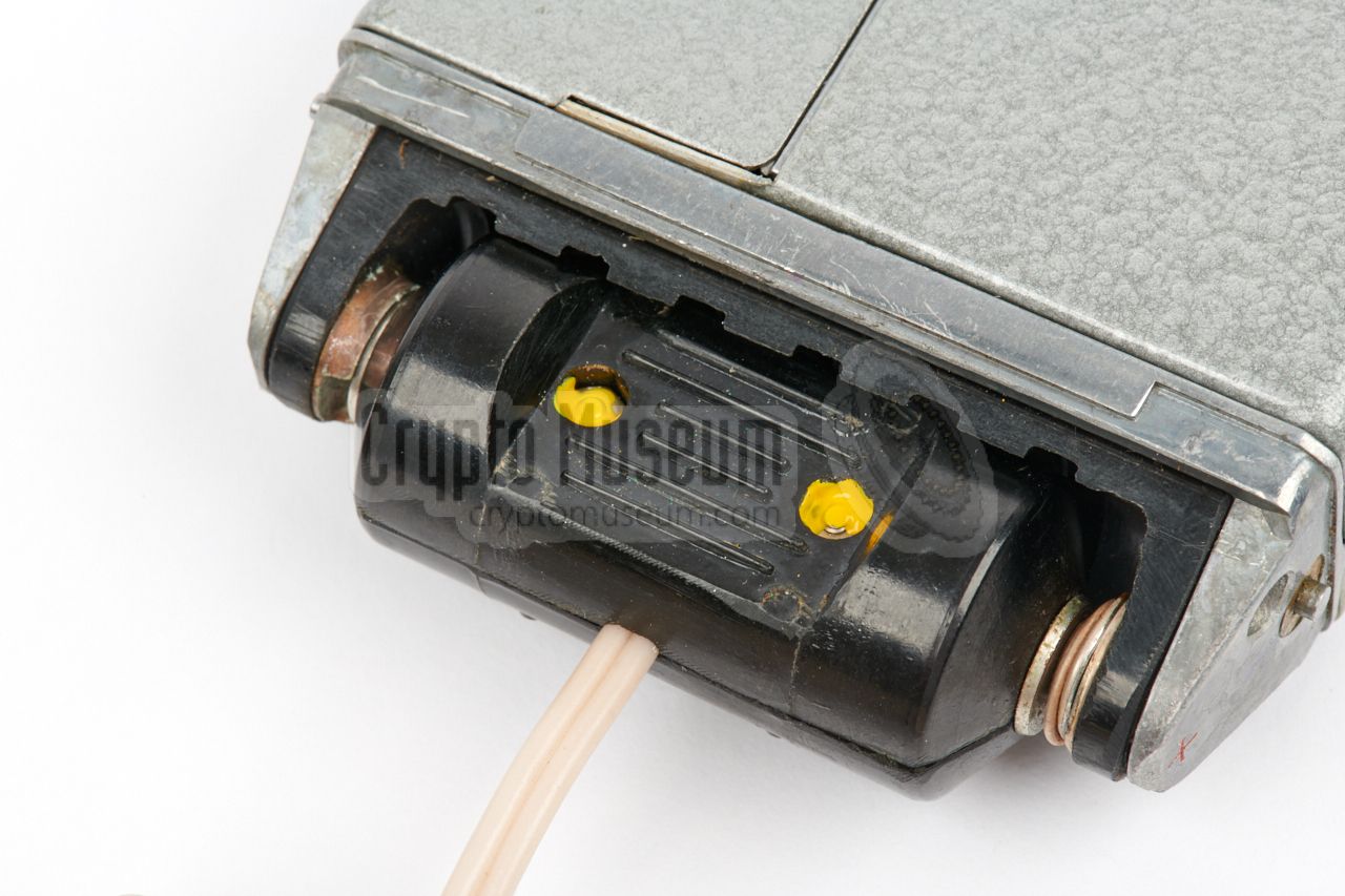
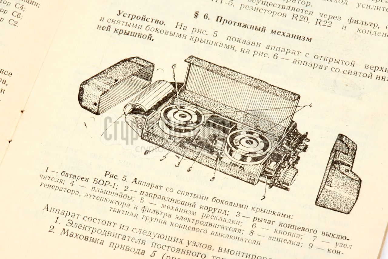
The diagram below shows the MEZON recorder with its cover open, as seen
from the front right. At the right are
three 3 mm jack sockets, marked with
coloured rings: white, blue and red. The white and blue sockets are for
connection of the remote control unit (RCU).
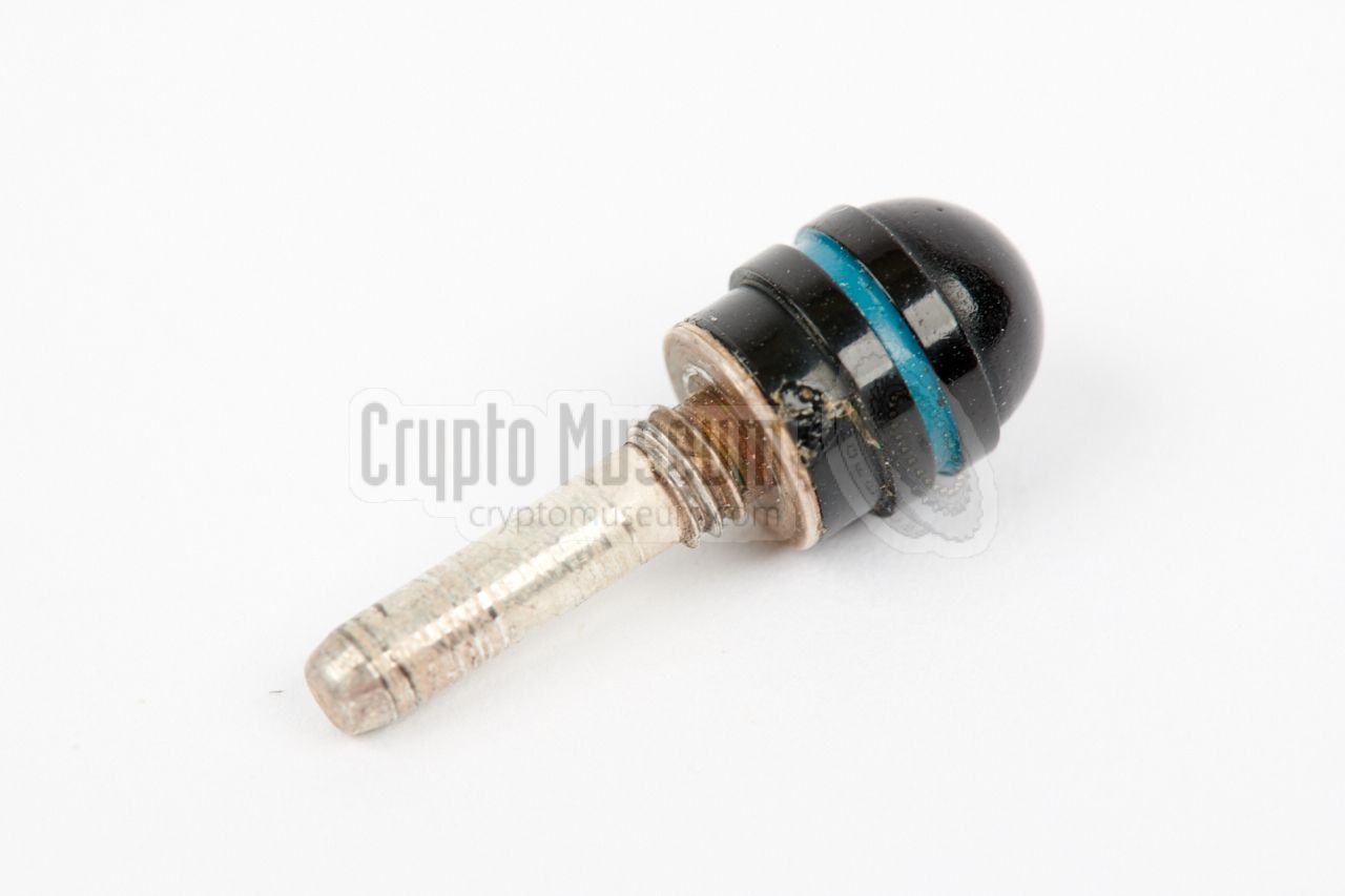
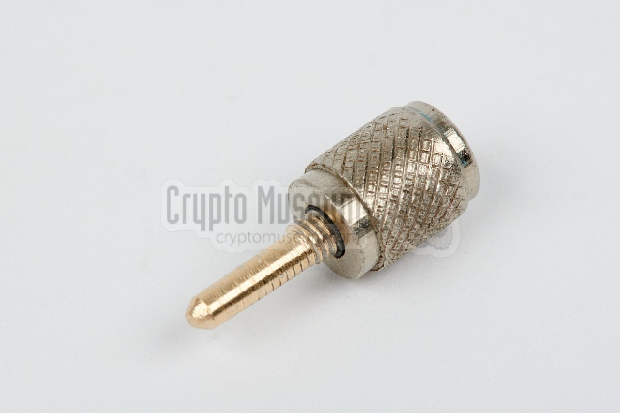
If the RCU is not used, a dummy plug (stub)
should be inserted into the blue socket. The red socket
at the right is used for connection of the microphone (when recording)
or for the earphone (when playing back).
Note that the plugs for these sockets are very rare,
as they have a a diameter of 3 mm
(not the more common 3.5 mm) and they have a short piece of M4 thread
that is used to fixate them in the socket.
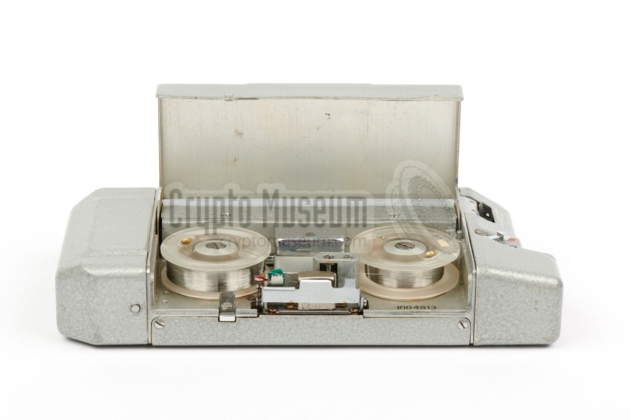
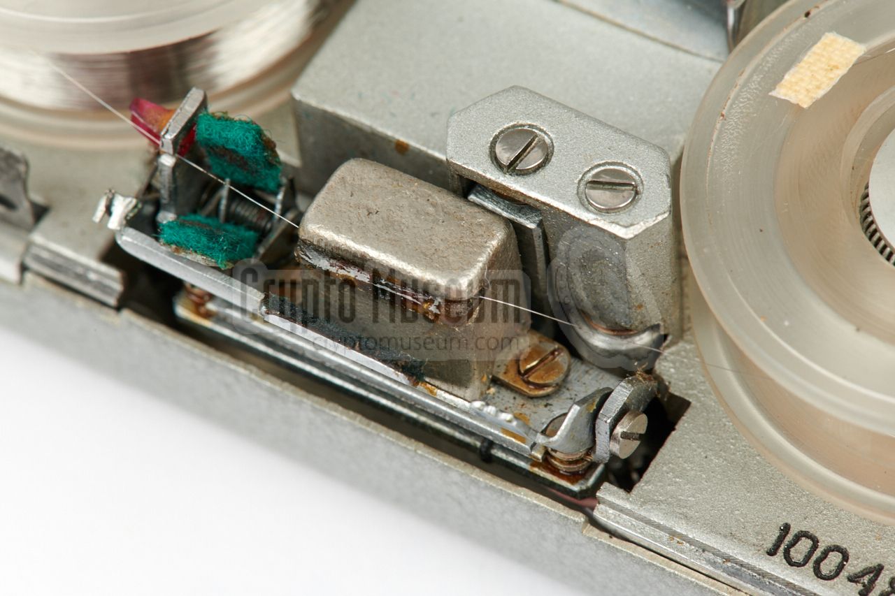
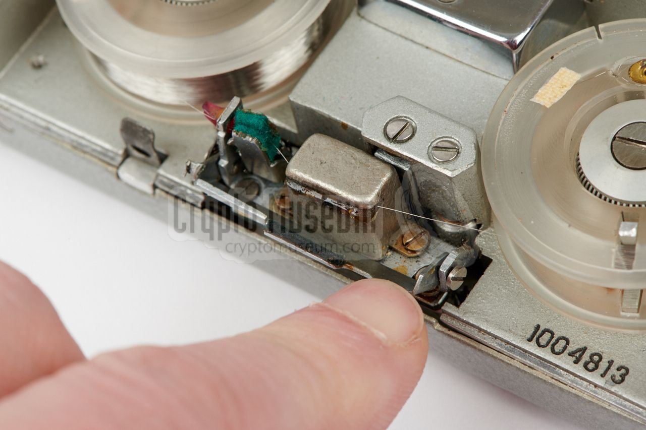
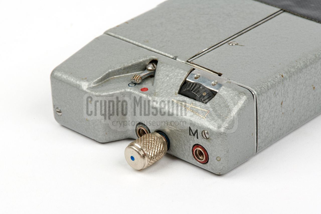
The actual recording wire is installed in the recording compartment, that
is protected by a hinged lid. The recording wire is just 0.05 mm thick
and runs between two spools,
past an electomagnetic head at the front.
Various cloth pads are present to keep the wire free from dust.
Note that when installing a wire spool, the spring-loaded cleaning pad
and the spring-loaded bar can be interlocked,
in such a way that the
wire path stays open.
This makes it easier to install a spool and guide the wire
past the head. It can be released by
pulling the bar further to the front.
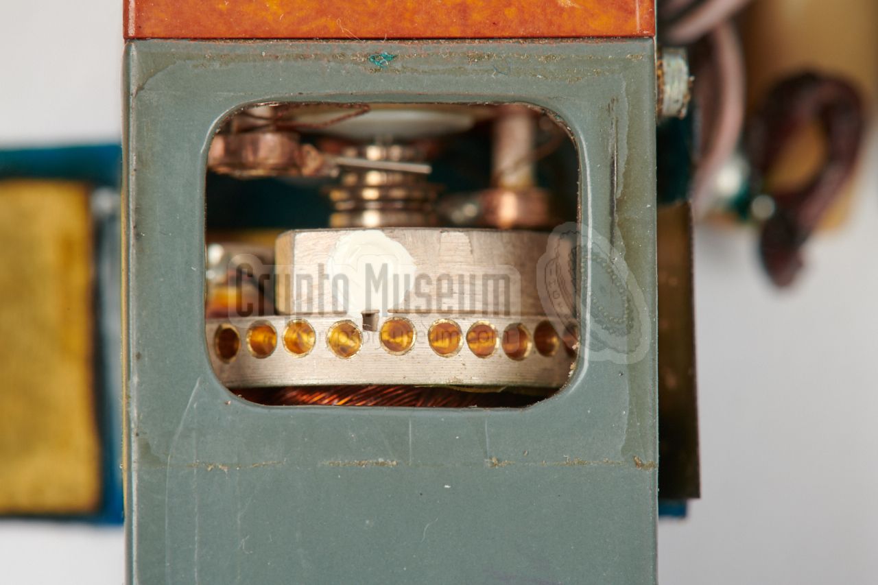
When the device is running, the audio head and the wire guides, are
slowly moved up and down by a slotted axle, to ensure that the wire is evenly
divided over the height of the pick-up spool.
|
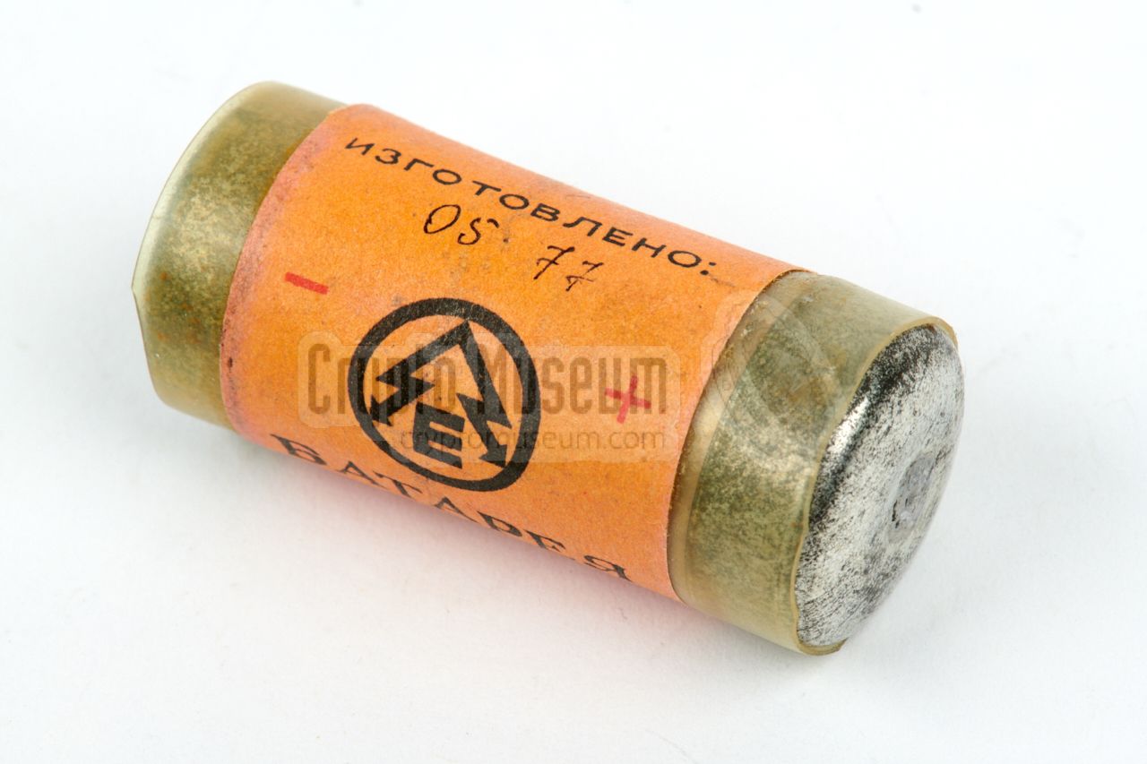
- Battery BOR
This was a standard rechargeable 7.3V battery
known as BOR or BOR-1
(Russian: БОР-1).
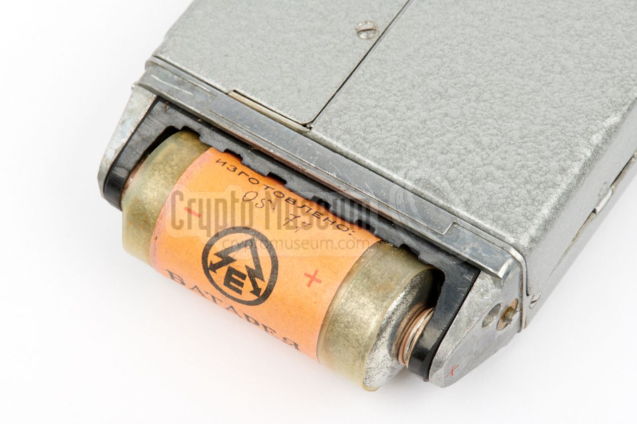
It is installed in the
battery compartment at the left side.
Two BOR-1 batteries were usually supplied with the kit,
but as far as we know, they are no longer in production.
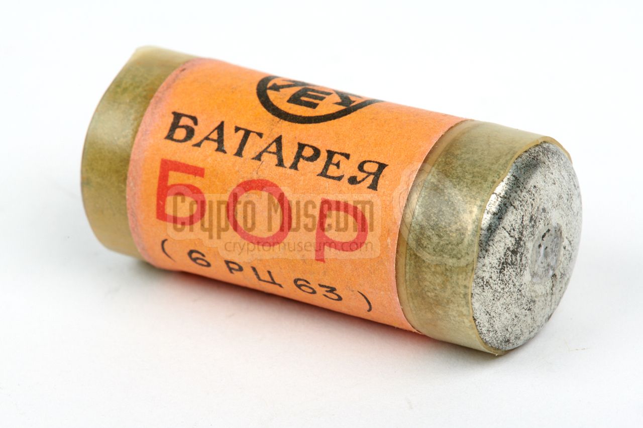
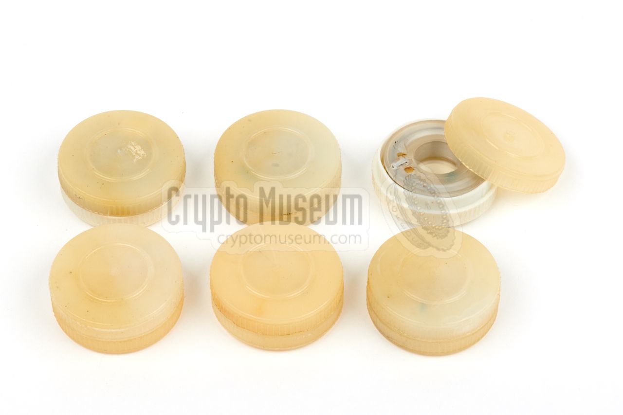
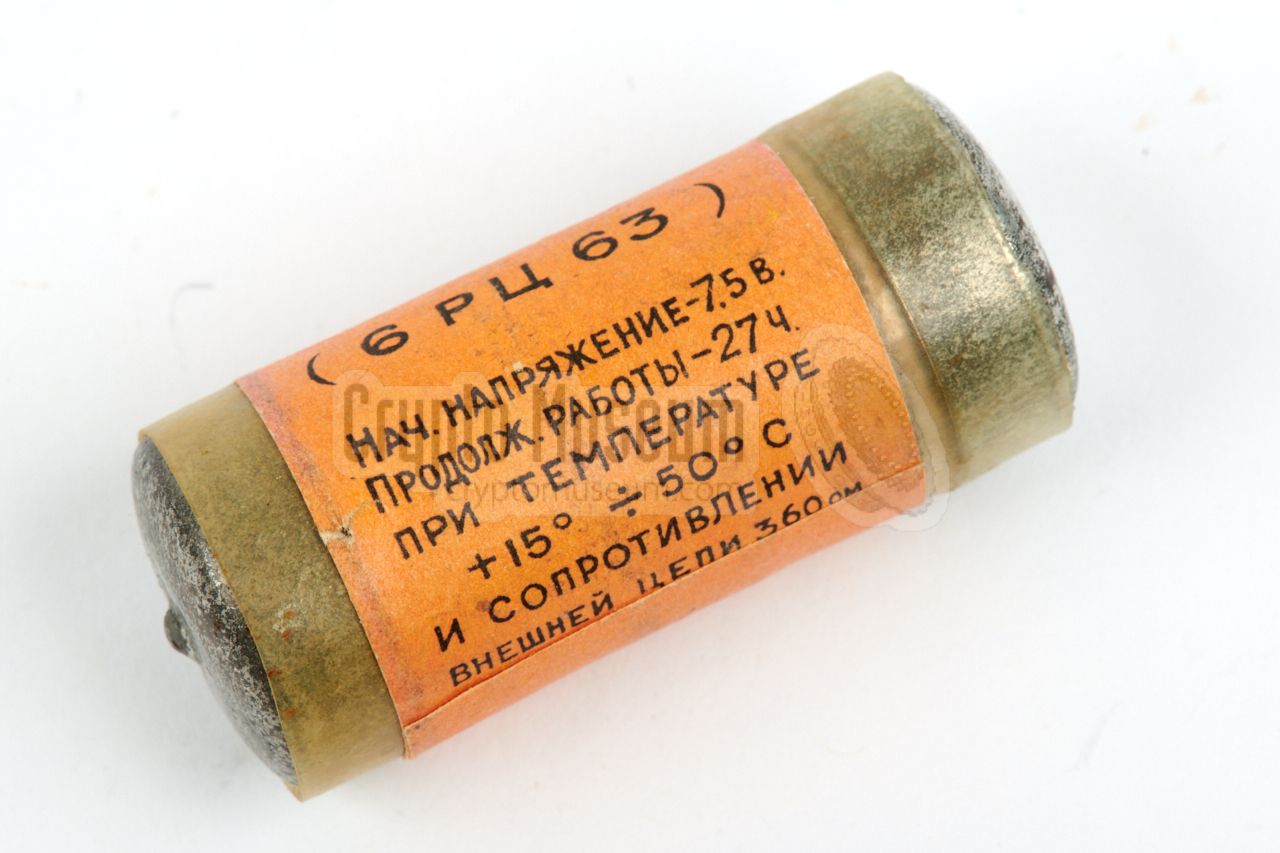
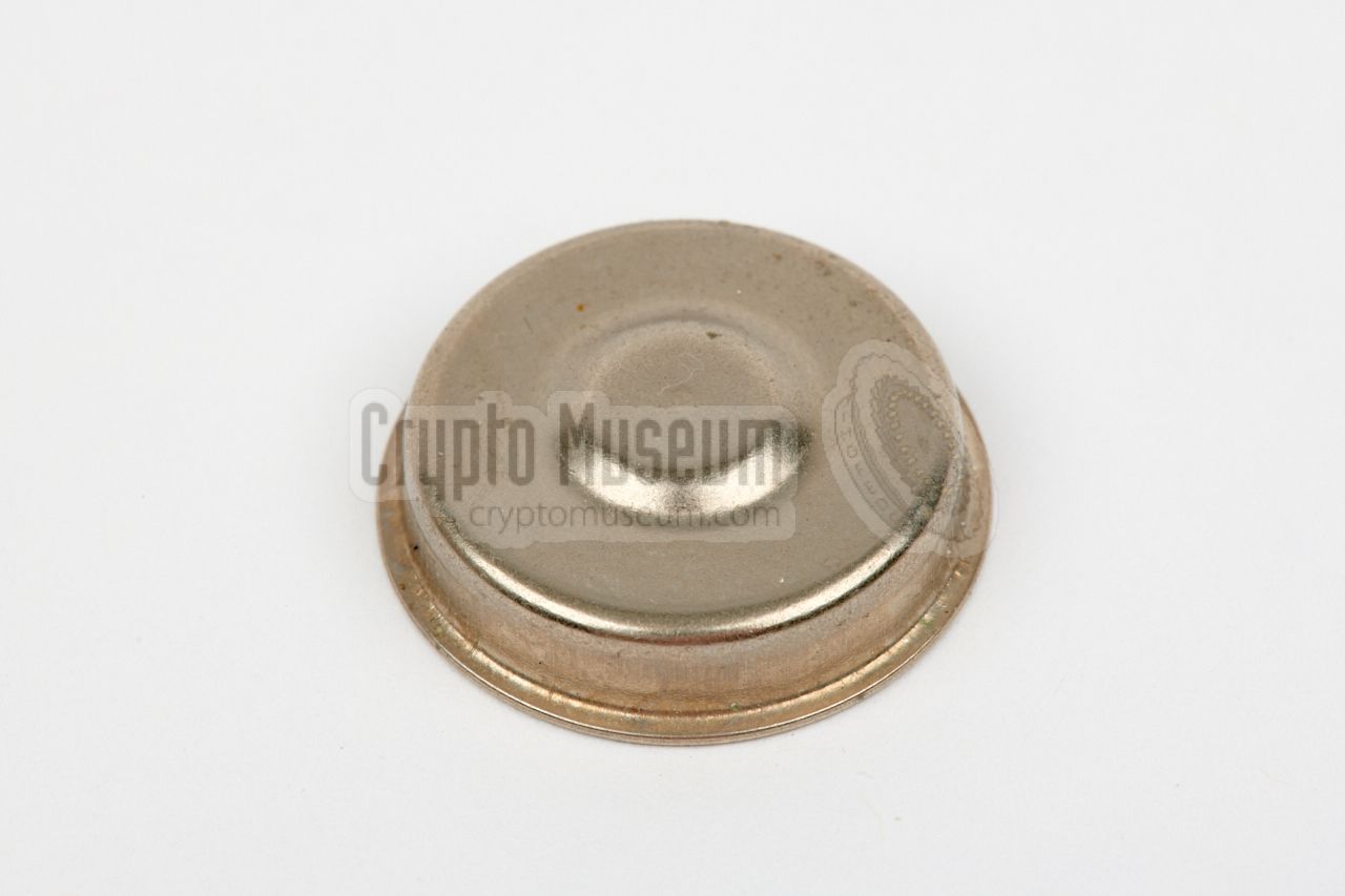
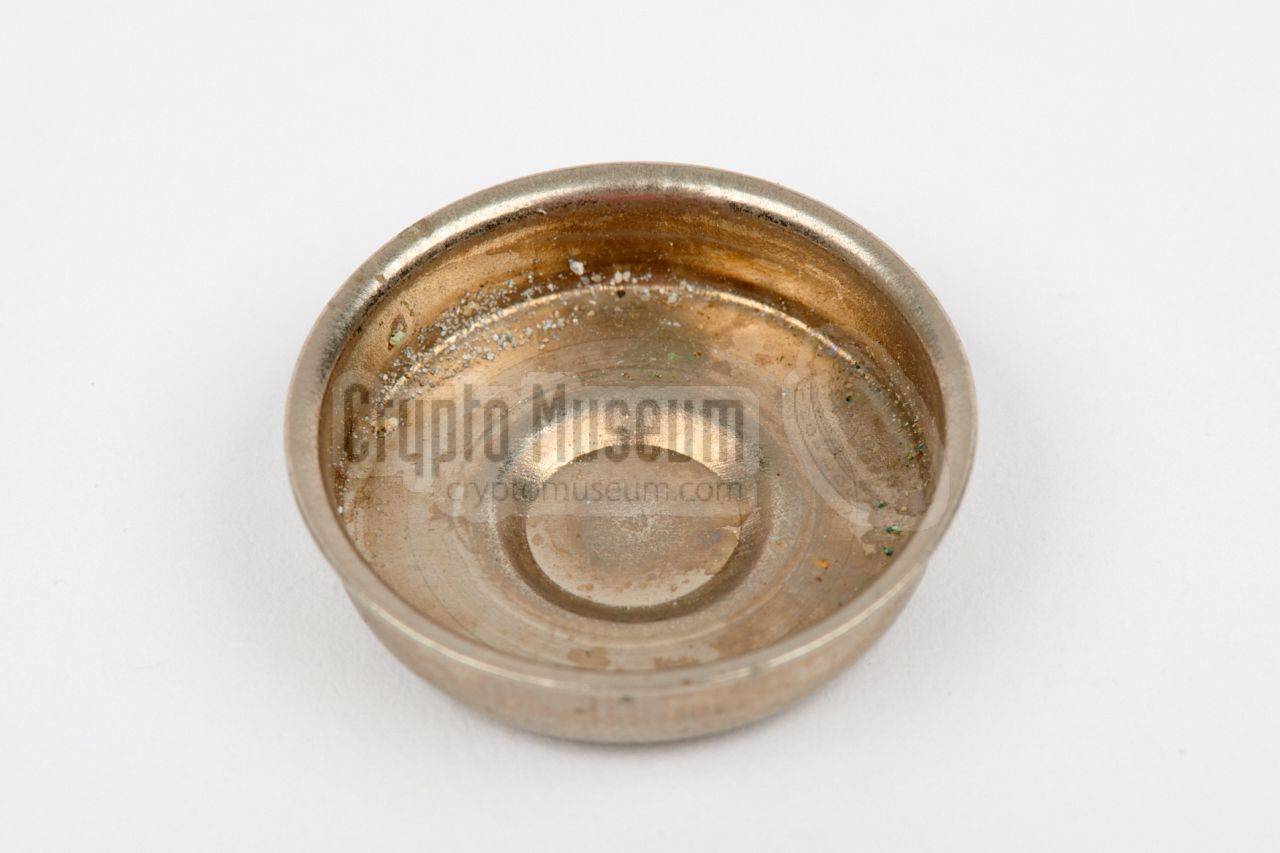
- Button cells
The set was supplied with a number of
metal RC-63 cups
that could hold OR-2K battery cells of 2.4V each
(total: 7.2V). This solution could be used in place of the BOR-1 battery
and fitted nicely in the existing battery compartment.
- SATURN battery box
Alternatively, the so-called 'SATURN' solution could be used, which is
basically a
metal box with five dry D-cell batteries.
It connects to the battery compartment of the recorder, by means
of a so-called SHUNT-adapter. The Saturn battery box was mainly used
in an office environment, for example when transcribing covertly recorded
conversations.
- Shunt connector
An external 7V DC power source could be used by installing the
DC adapter (shunt) in the battery compartment (instead of a battery)
and connecting a DC source to the two wires. A separate (fixed) shunt is
supplied with the SATURN battery box (above).
|
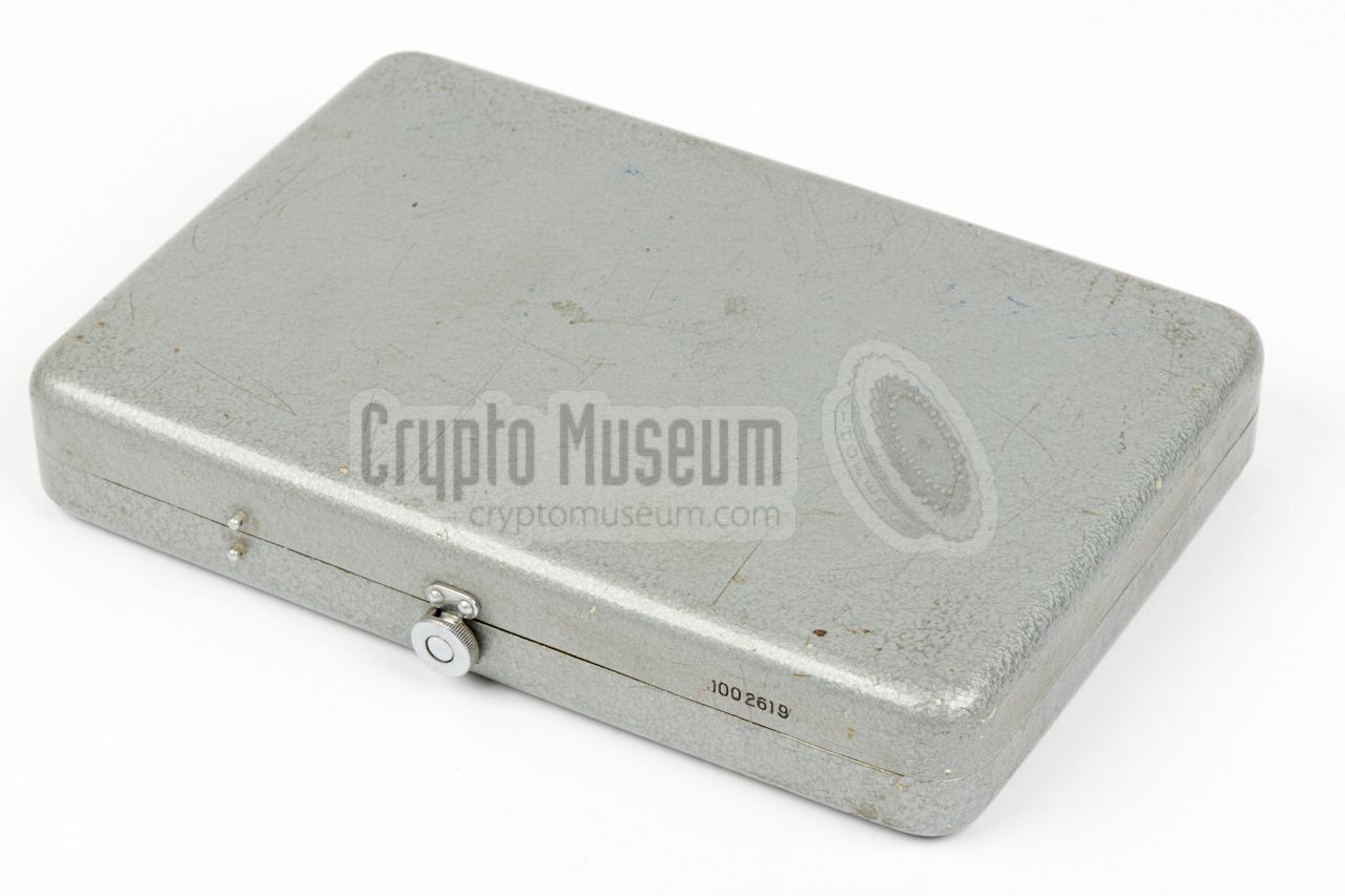
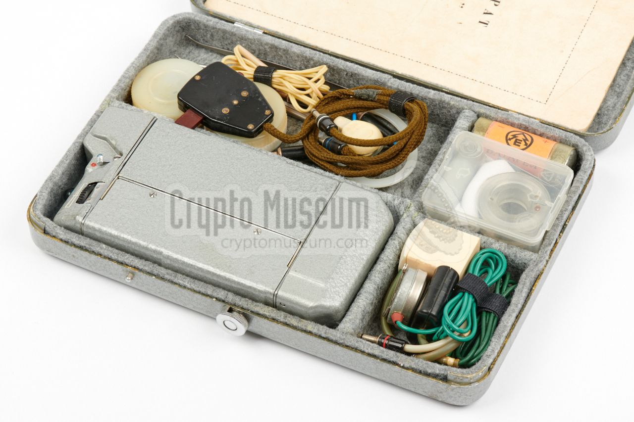
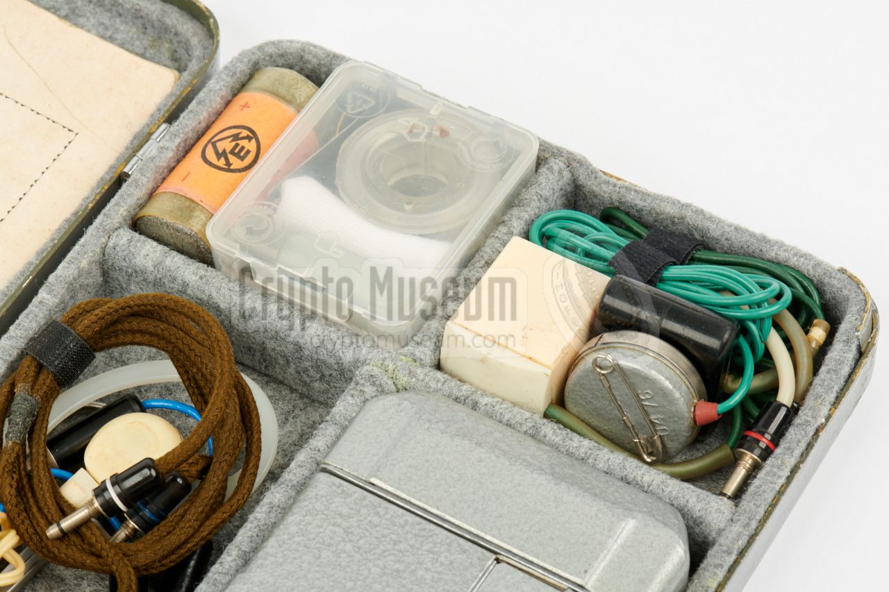
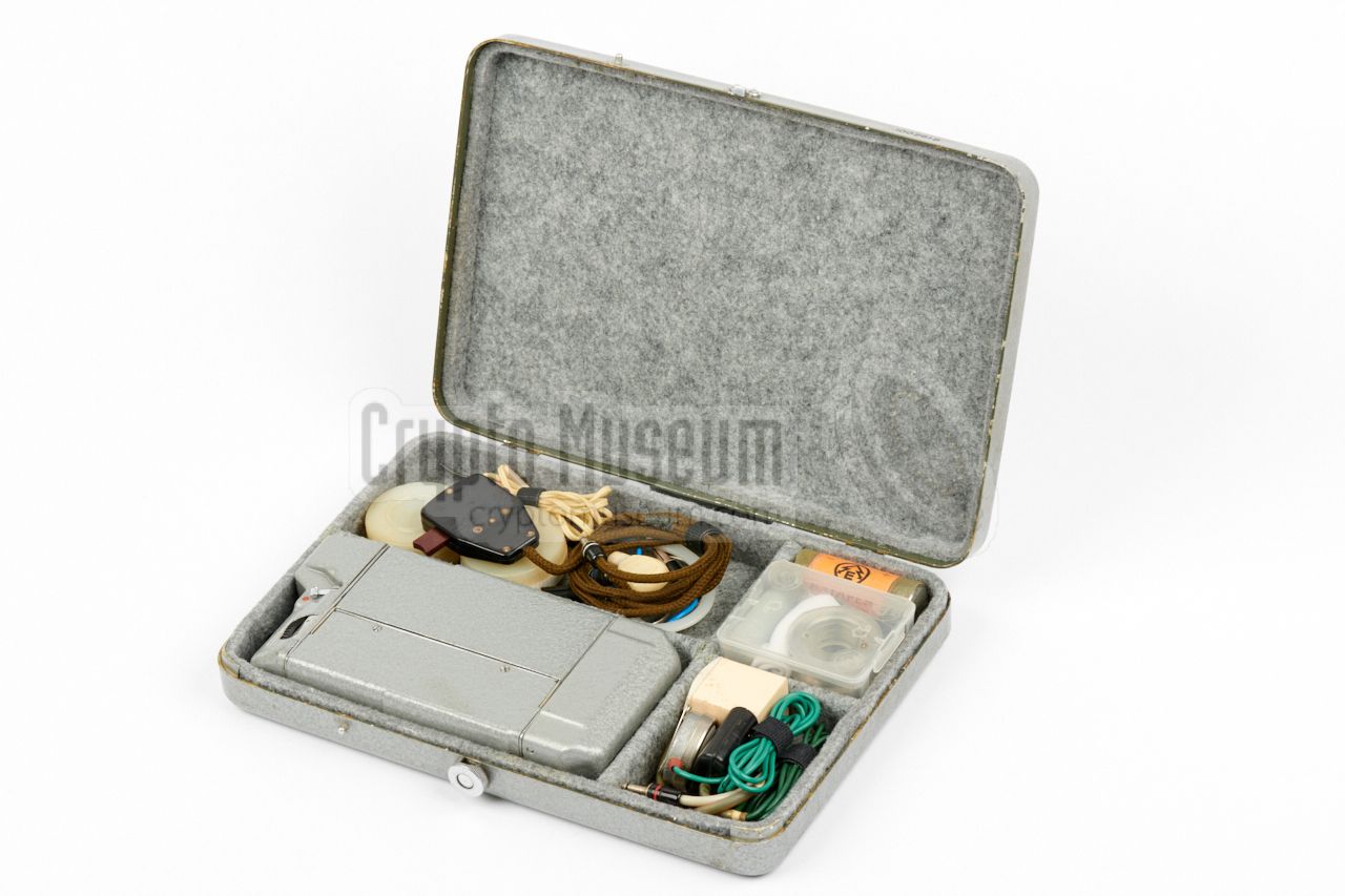
MEZON was supplied in two metal storage cases: a lower one, which contained
the recorder and some accessories and tools in polystyrene foam,
and a higher one with the additional equipment, spares and a covert carrying case.
The image on the right shows the lower case in which the foam interior has
been replaced by felt.
The higher storage case for the additional equipment and spares
is currently missing from our collection.
|
|
|
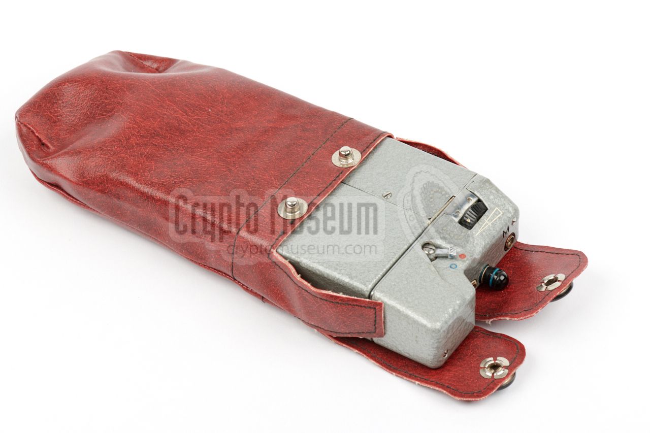
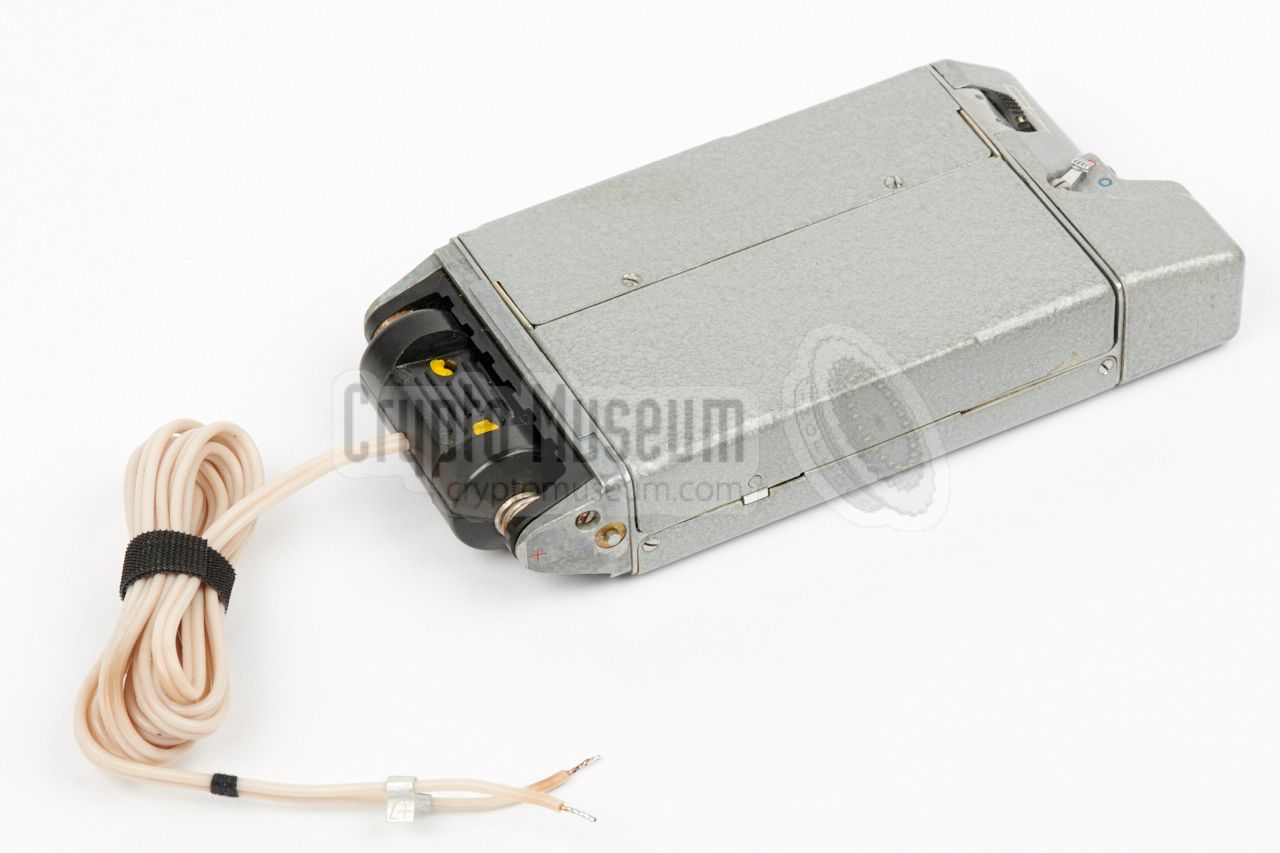
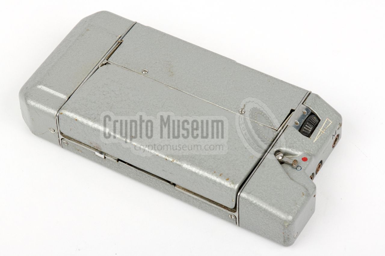
The actual recorder measures just 158 x 76 x 27 mm and weighs 492 grams
without batteries. It was painted either grey hammerite or black, and
was usually carried in a special cloth holster, that could be
hidden under the operative's clothing.
In such situations, the microphone was hidden elsewhere under the clothing,
whilst the remote control unit was carried in one of the pockets.
|
|
|
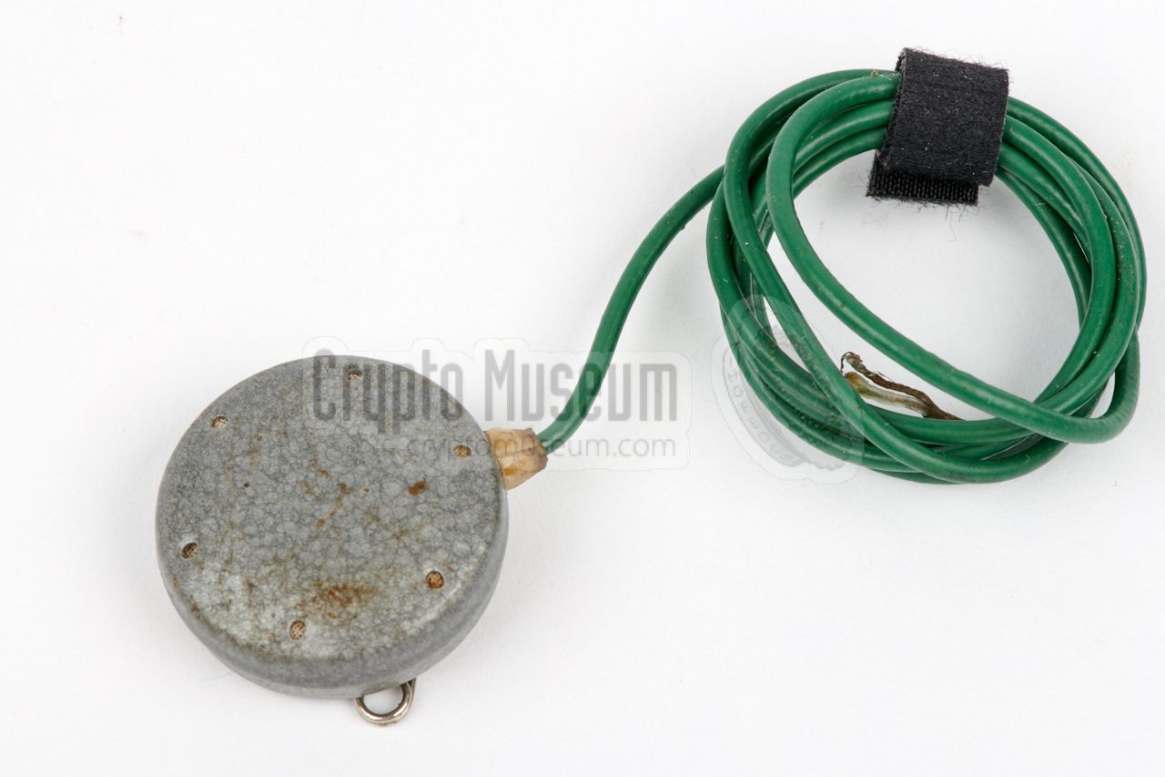
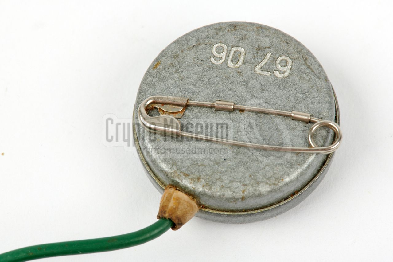
MEZON can be used with virtually any type of dynamic microphone,
but was usually supplied with a so-called NEVA
or a T-65 microphone.
The microphone usually has a green wire with a red-marked 3 mm jack
at the end. It should be connected to the rightmost socket of MEZON.
The microphone has a
safety pin at the rear,
allowing it to be affixed to the clothing.
Note that when playing back a recording, the internal circuitry is reversed,
as a result of which the microphone will act as a speaker. As it is a
dynamic microphone element, this is possible.
|
|
|
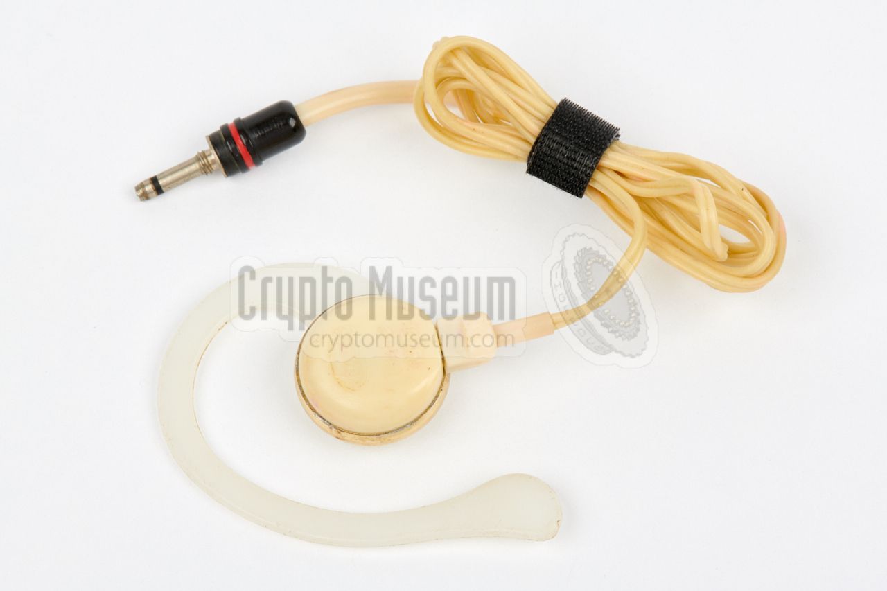
For playing back the recorded audio, a standard TM-2 earphone was
supplied, which had to be connected to the microphone socket (M).
In the absense of a suitable earphone, it was also possible to use the
(dynamic) microphone element as a speaker, albeit with less privacy
and a somewhat reduced audio quality.
|
|
|
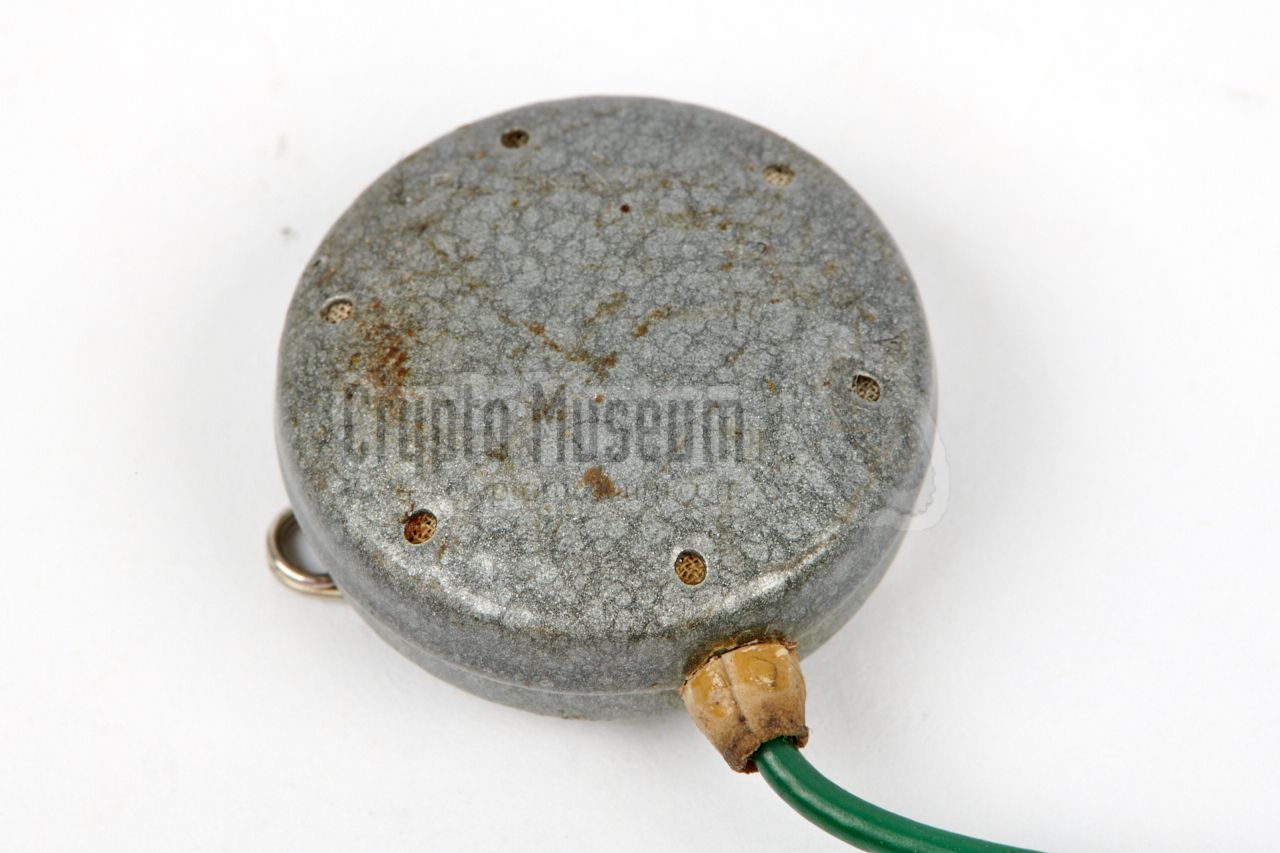
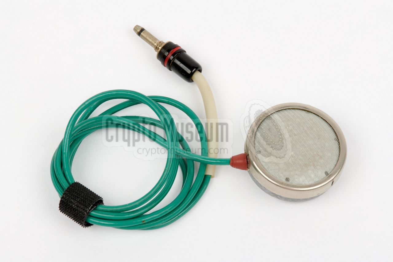
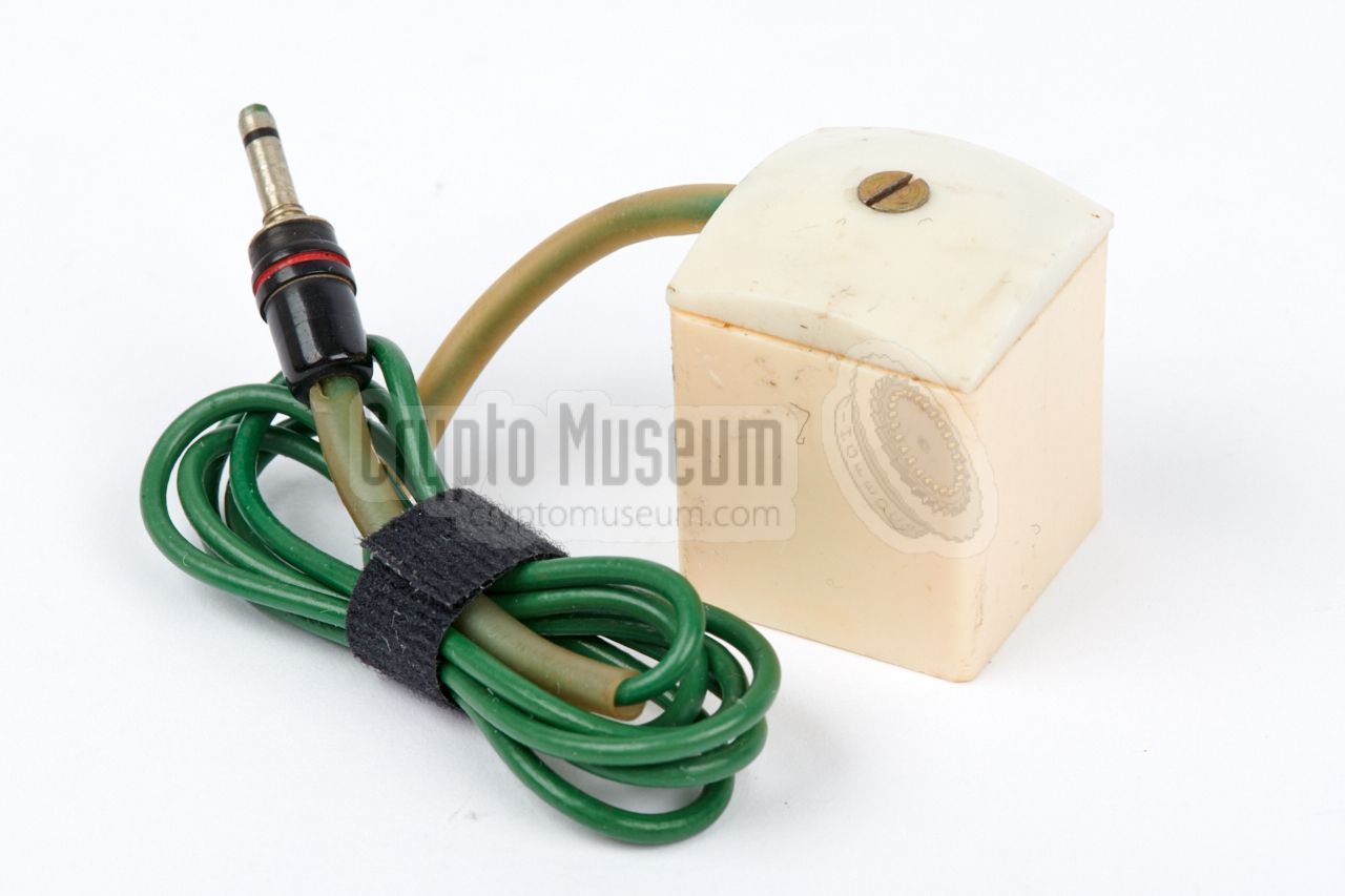
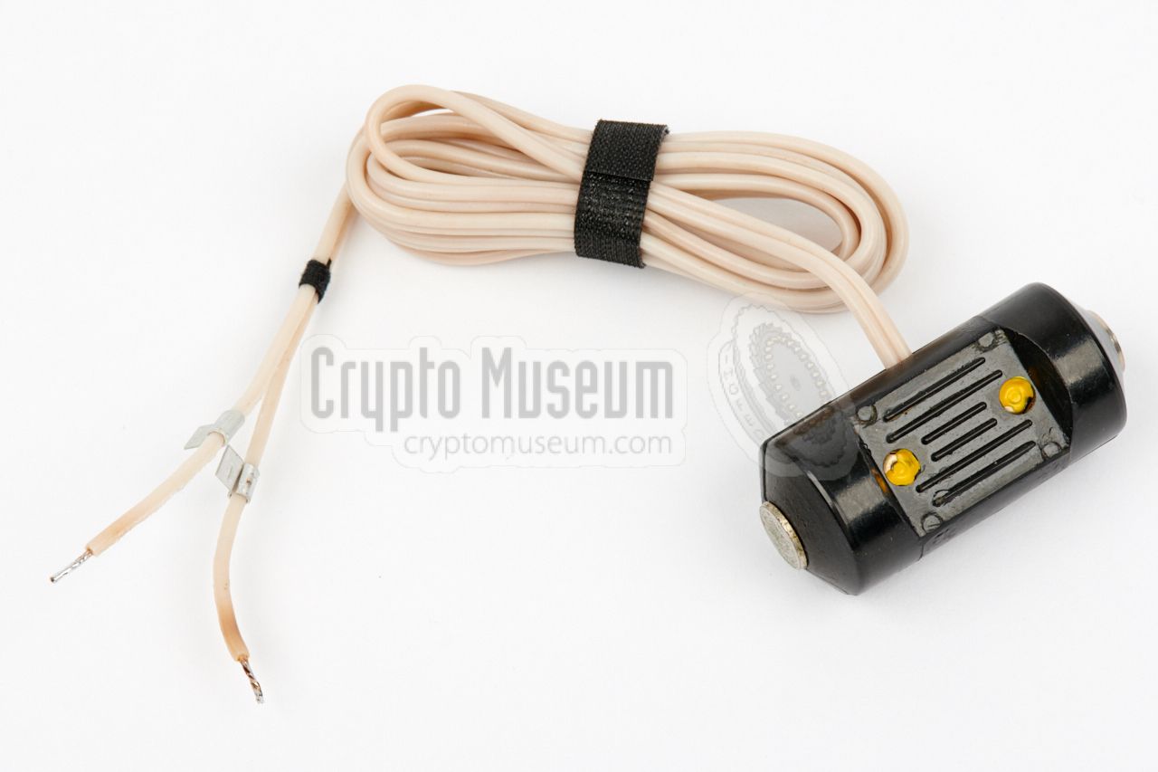
For recording a telephone conversation without physically connecting the
recorder to the line, a special pickup coil was available. It should be
placed in the vicinity of the internal transformer of the
(analogue) telephone set.
In most cases, it was sufficient to place the pickup coil behind the
telephone set in order to pick up a clear hum-free audio signal.
|
|
|
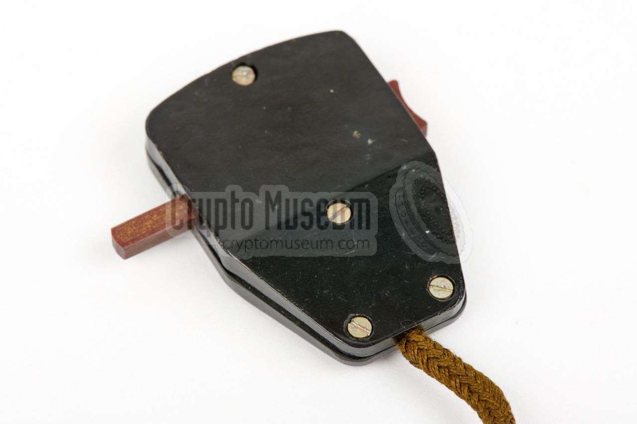
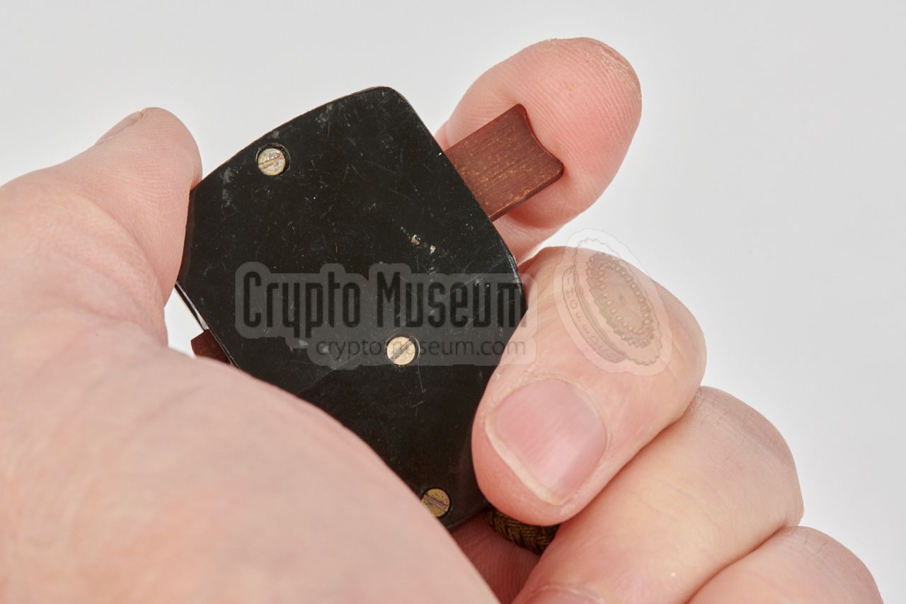
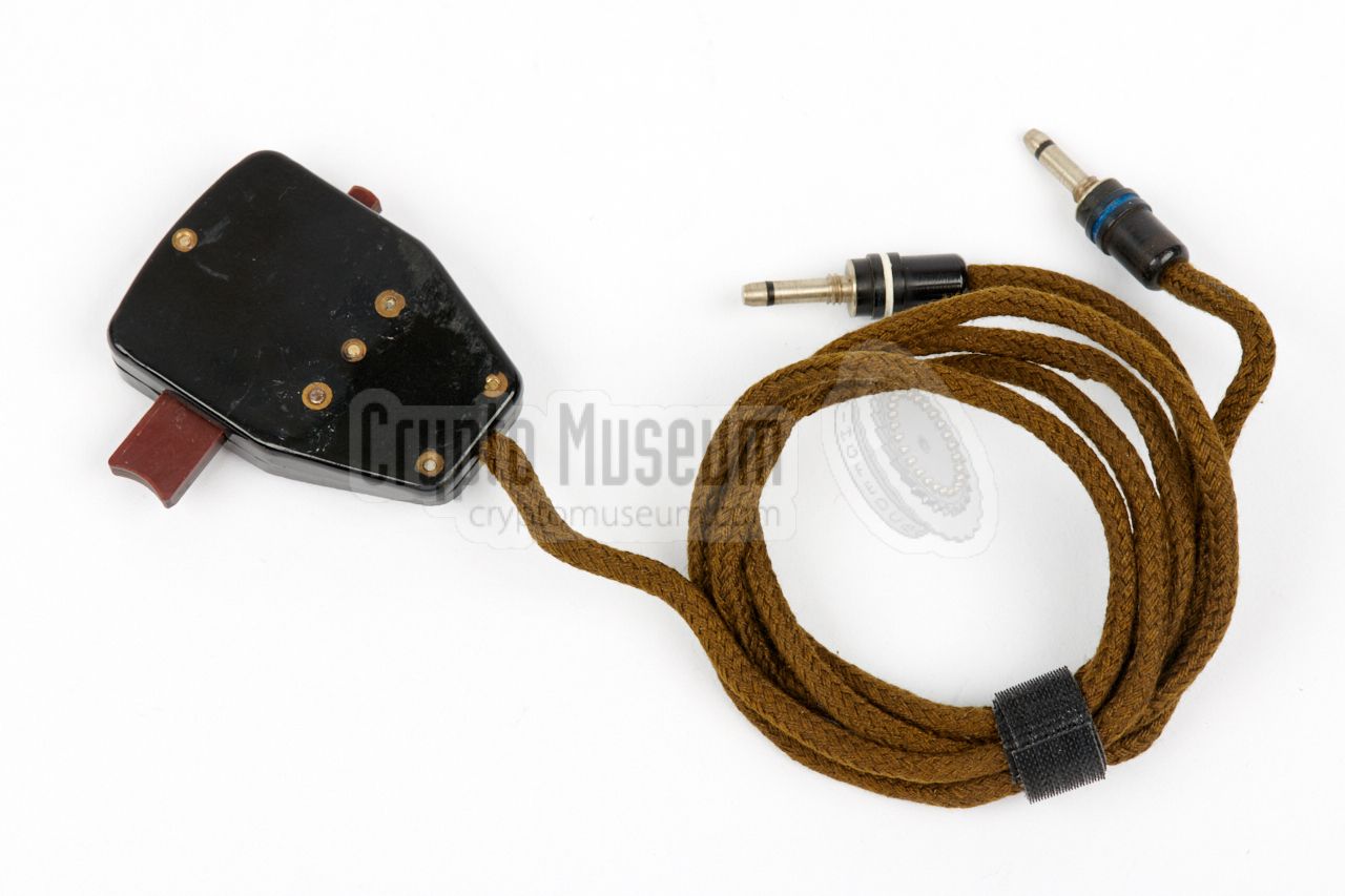
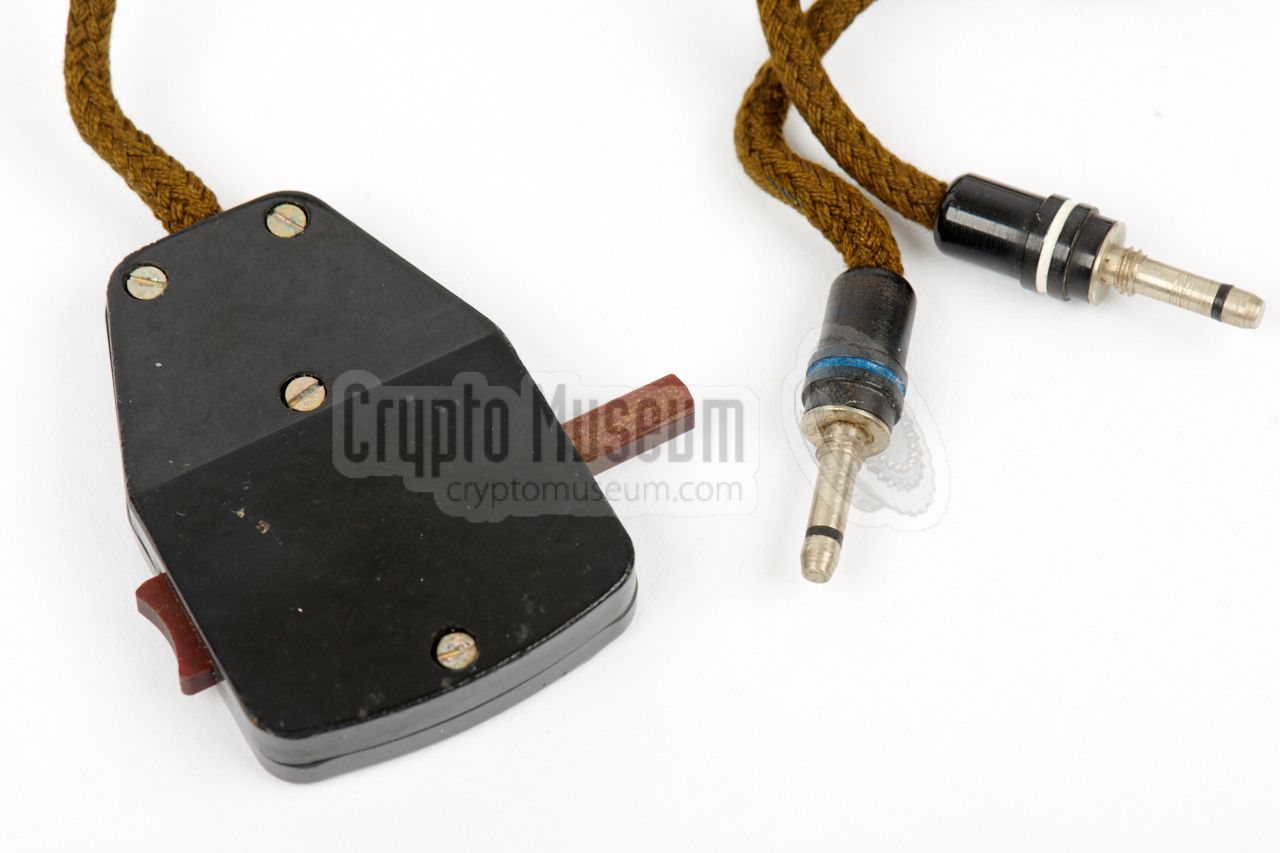
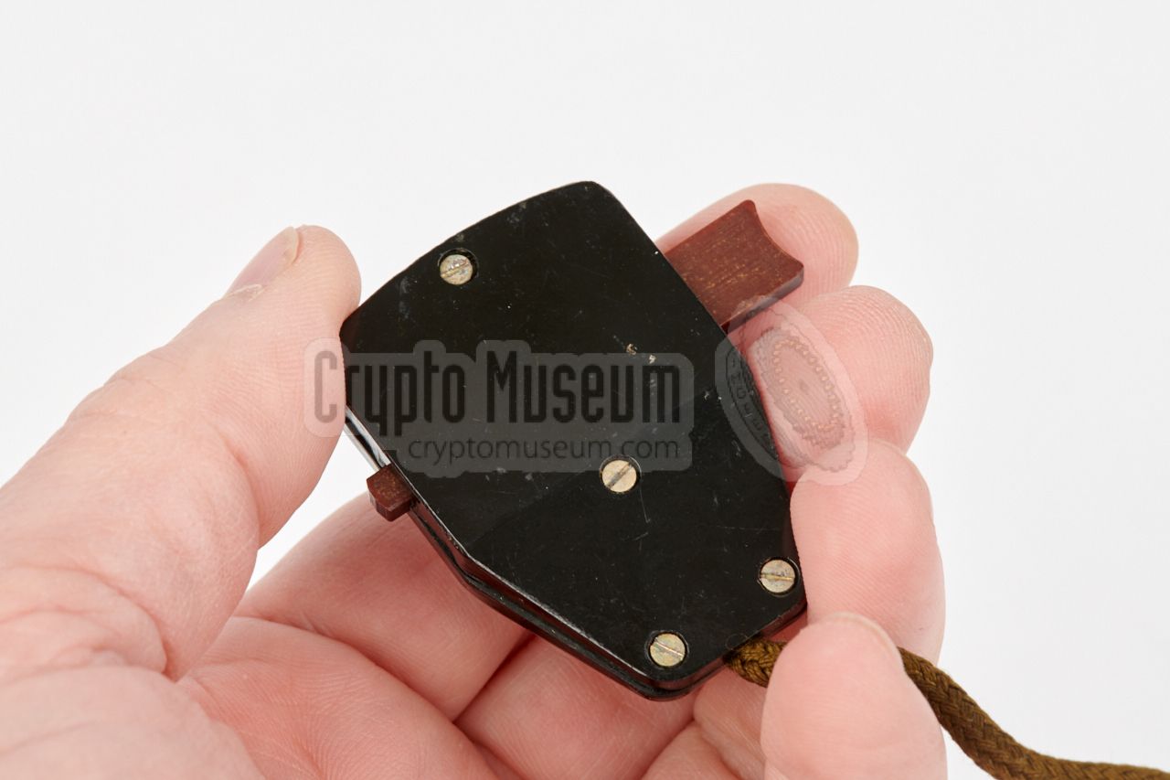
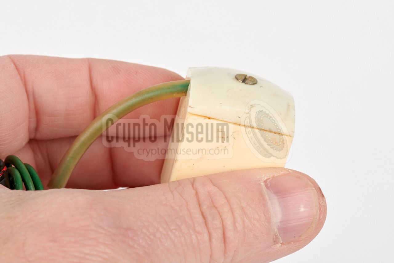
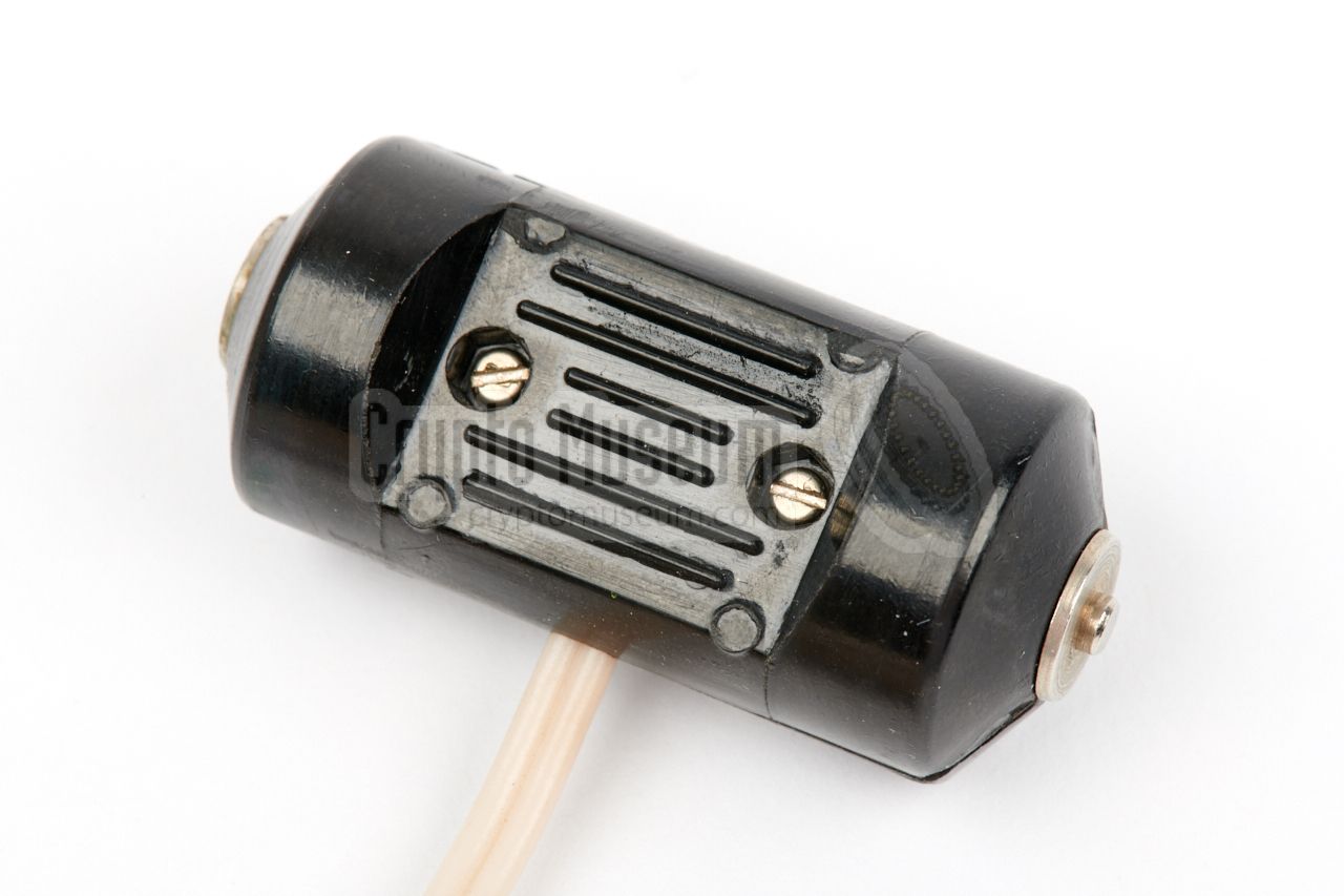
A simple handheld remote control unit was supplied, to allow concealed
operation of the recorder. For that purpose, the remote control unit could
be carried in the pocket.
The device is made of (black) bakelite and has a shift-switch at the centre.
It is connected to the recorder via an 80 cm cloth wire, with two screw-on
3 mm jacks at the end. The plugs are marked with a blue and a white ring,
and should be inserted into the corresponding sockets on the
right side
of the body of the recorder.
|
|
|
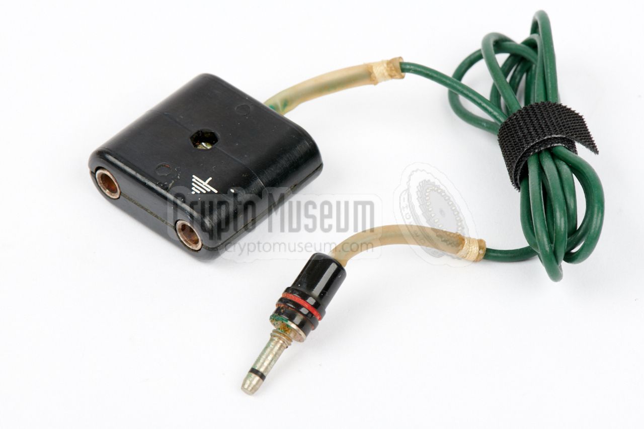
Apart from the supplied microphone,
it was also possible to connect the recorder to an external audio
source, such as an amplifier or a receiver, by using the audio adapter
shown in the image on the right.
Likewise, this cable can also be used to connect the output of MEZON
to the input of an external amplifier when playing back.
|
|
|
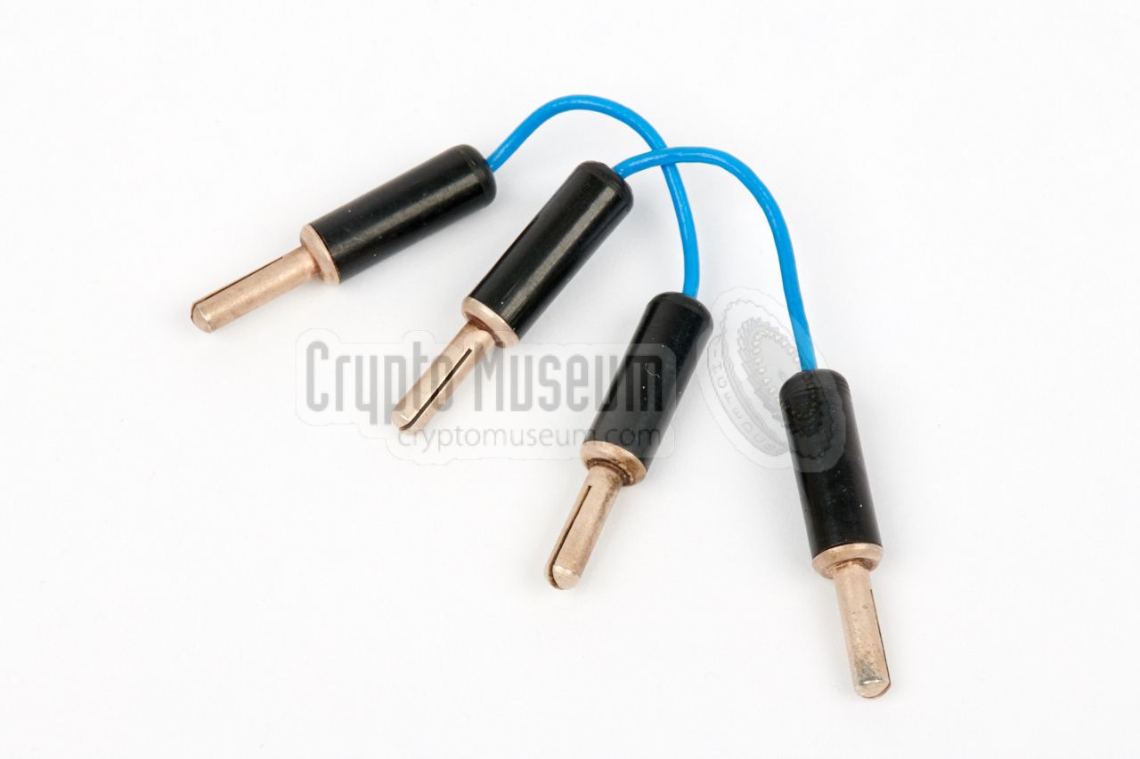
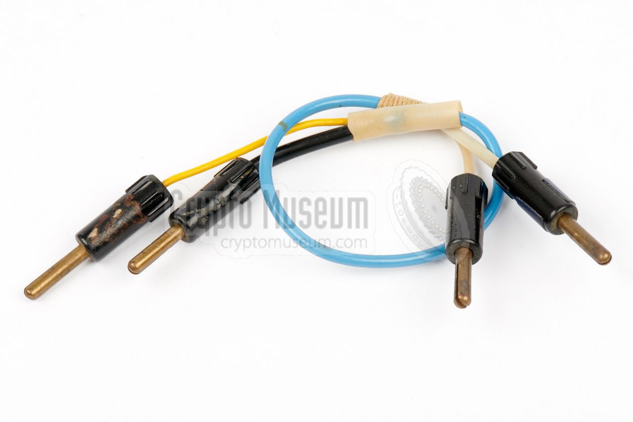
In order to connect the adapter above to an external audio device,
two short blue wires with banana plugs at either end – shown in the
image on the right – were supplied as part of the kit.
If these wires are missing, any other banana cables can be used, and it
is also possible to make a suitable reproduction.
|
|
|
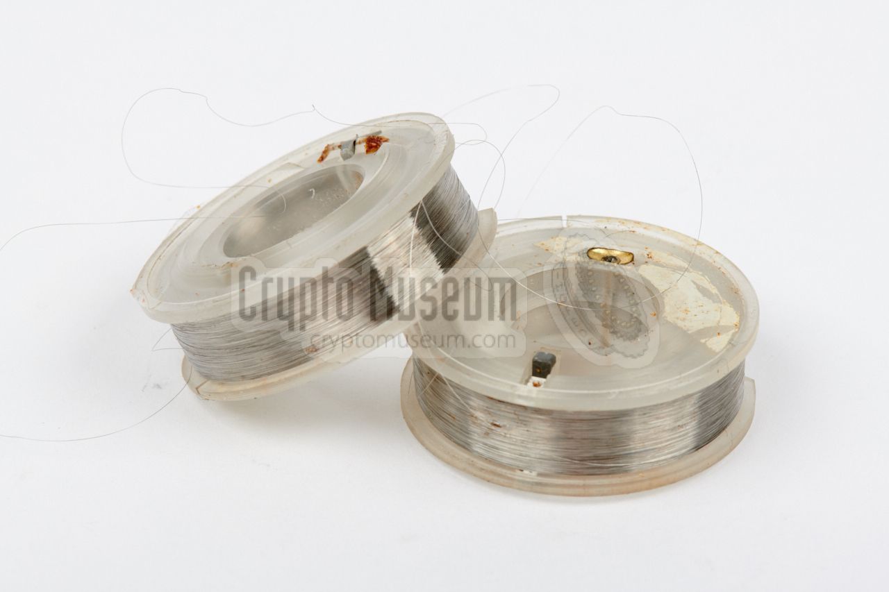
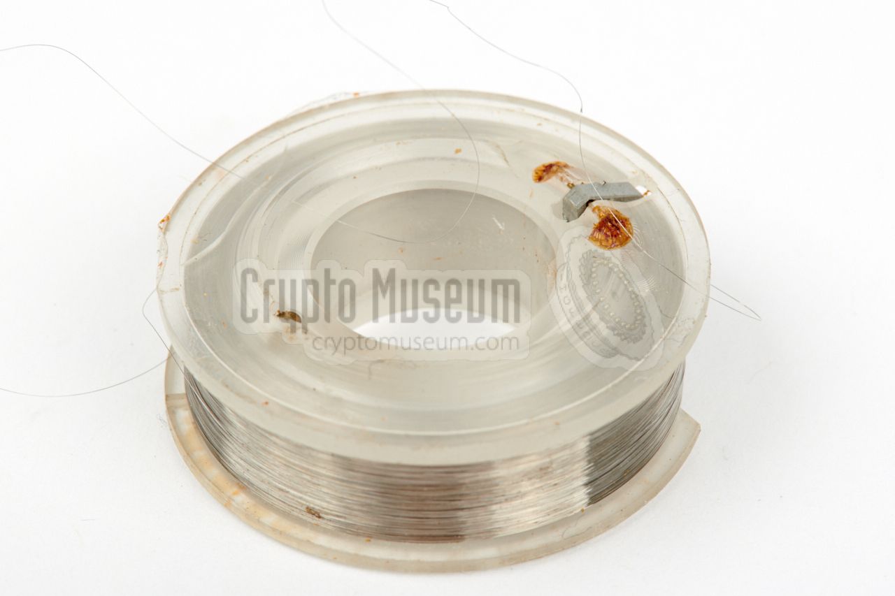
Apart from the spools that are present inside the recorder,
some spare ones were supplied with the kit. Two were stored in the
smaller storage case, together with the recorder, whilst the remaining
stock was held in the larger one.
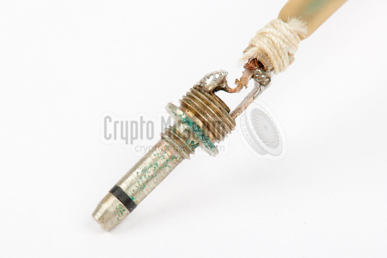
The wire on these spools is just 0.05 mm thick and repairing a broken
wire requires some skills, but with the right type of knot it can be done.
|
|
|
|
|
Rechargeable battery
BOR-1
|
|
|
|
|
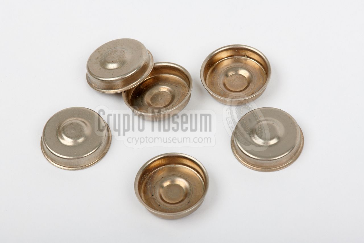
Cups for button cells
RC-63
|
|
|
As an alternative to the standard rechargeable BOR battery,
it was possible to use a number of OR-2K buttons cells to
get the required 7 Volts.
In order to fit the button cells in the available
space, metal cups – known as RC-63 – were supplied,
as shown in the image on the right .
|
|
|
|
|
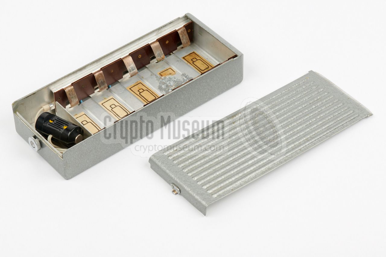
External battery 'Saturn'
|
|
|
When using the recorder in playback mode, for example when transcribing a
covertly recorded conversation, it was possible to replace the internal
rechargeable battery by the external battery box shown
in the image on the right.
This metal box is known as Saturn, and offers space for five large
1.5V D-type mono cells. The compartment towards the front holds a short
cable with a SHUNT-adapter at the end. The SHUNT should be
placed in MEZON's battery compartment
instead of the regular battery.
|
|
|
It was also possible to power the recorder by an external 7V DC source,
using the so-called SHUNT-adapter, which was installed instead of the
internal battery. In that case, the two wires from the shunt adapter should
be connected to the external DC power source.
A shunt adapter is also supplied as a fixed part of the external
SATURN battery box,
that was supplied in the larger storage case.
|
|
|
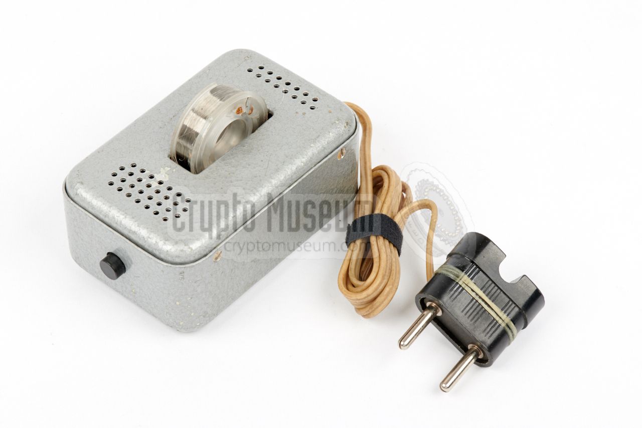
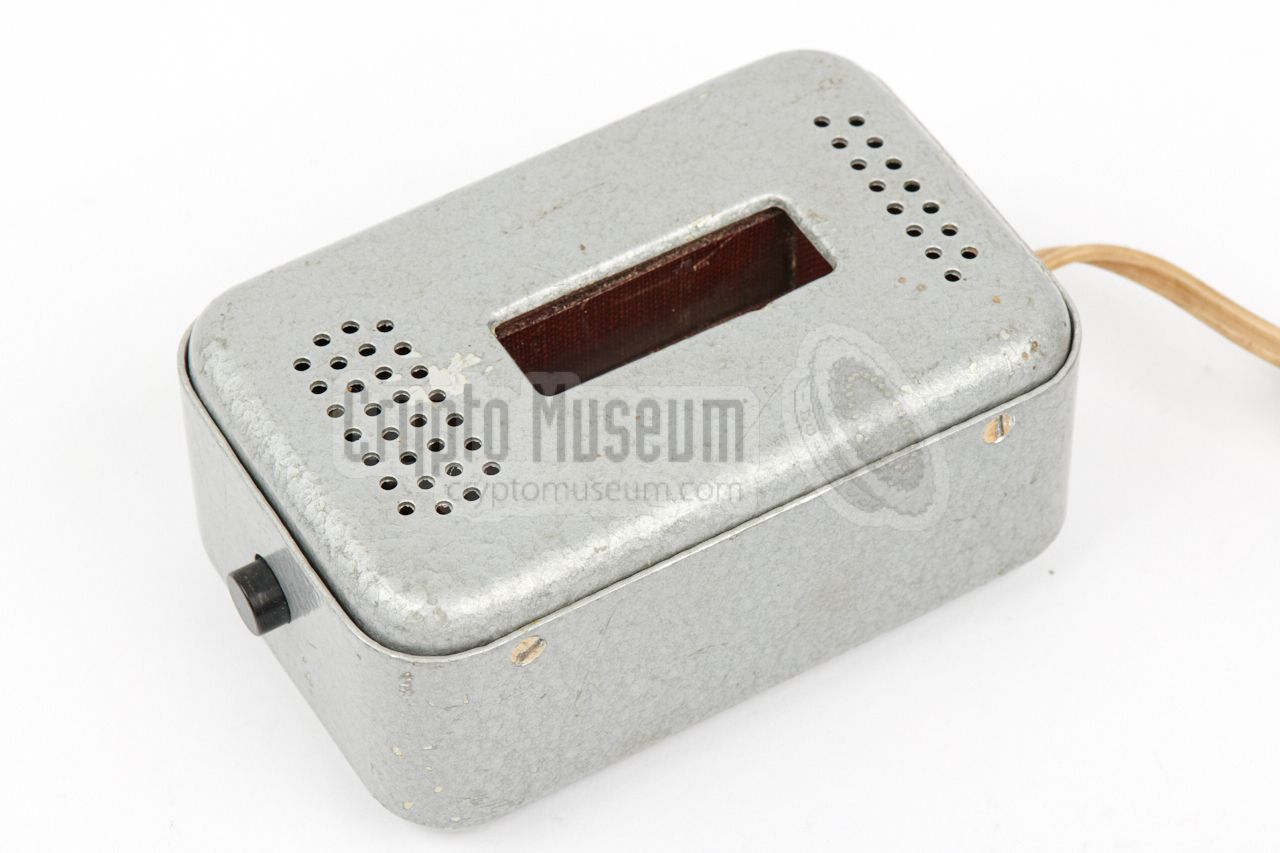
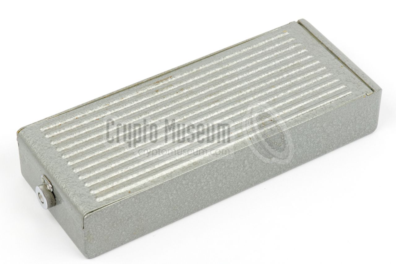
MEZON can only record and play-back.
It has no facilities to erase a recording. In order to erase a
recorded conversation the external eraser device
shown in the image on the right, had to be used.
The spool with wire has to be installed in the bay at the top, after which
the device should be connected to the mains. It contains a coil that produces
an alternating magnetic field that is sufficiently strong to erase the wire,
as soon as the black button at the front is pressed.
|
|
|
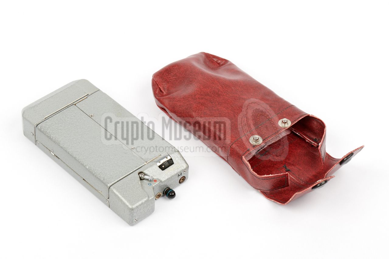
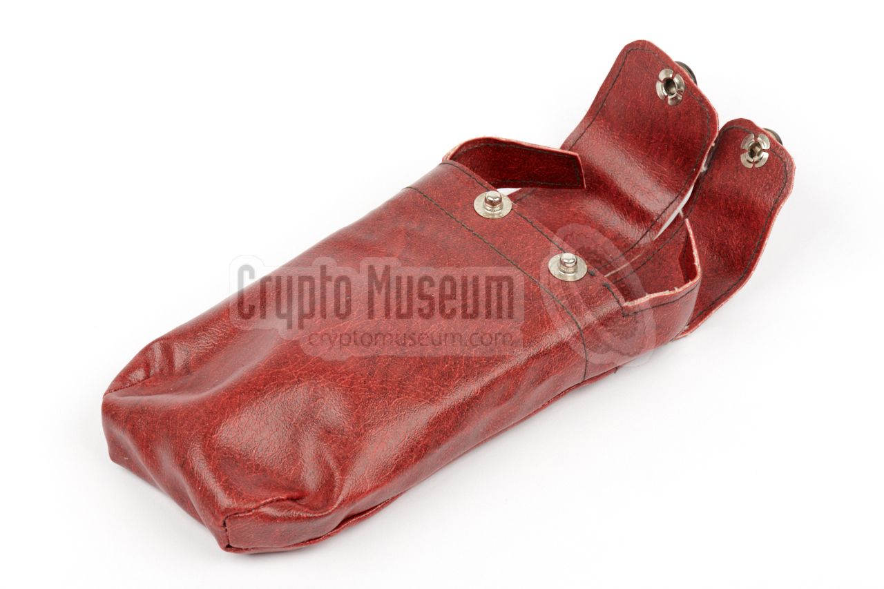
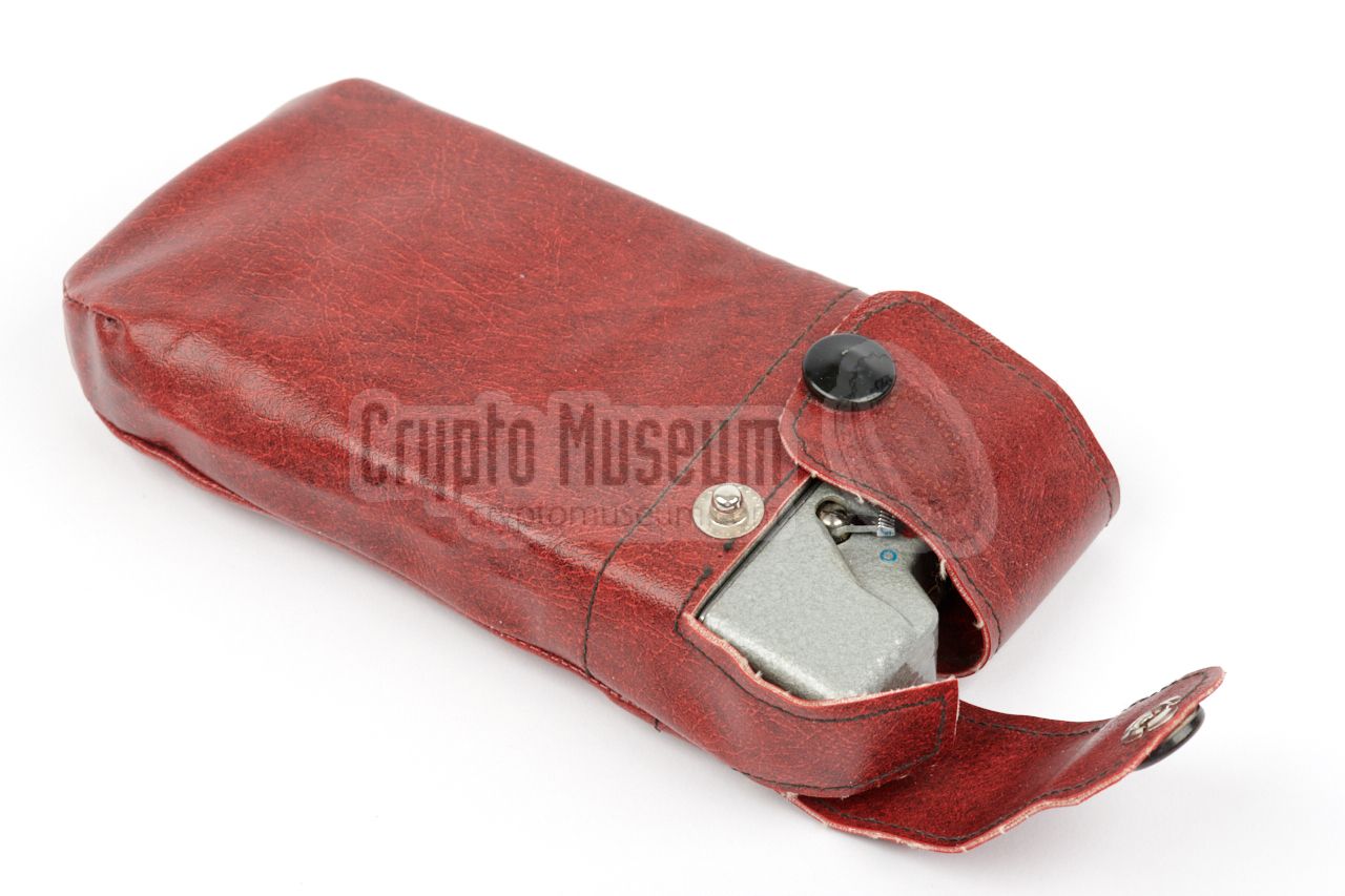
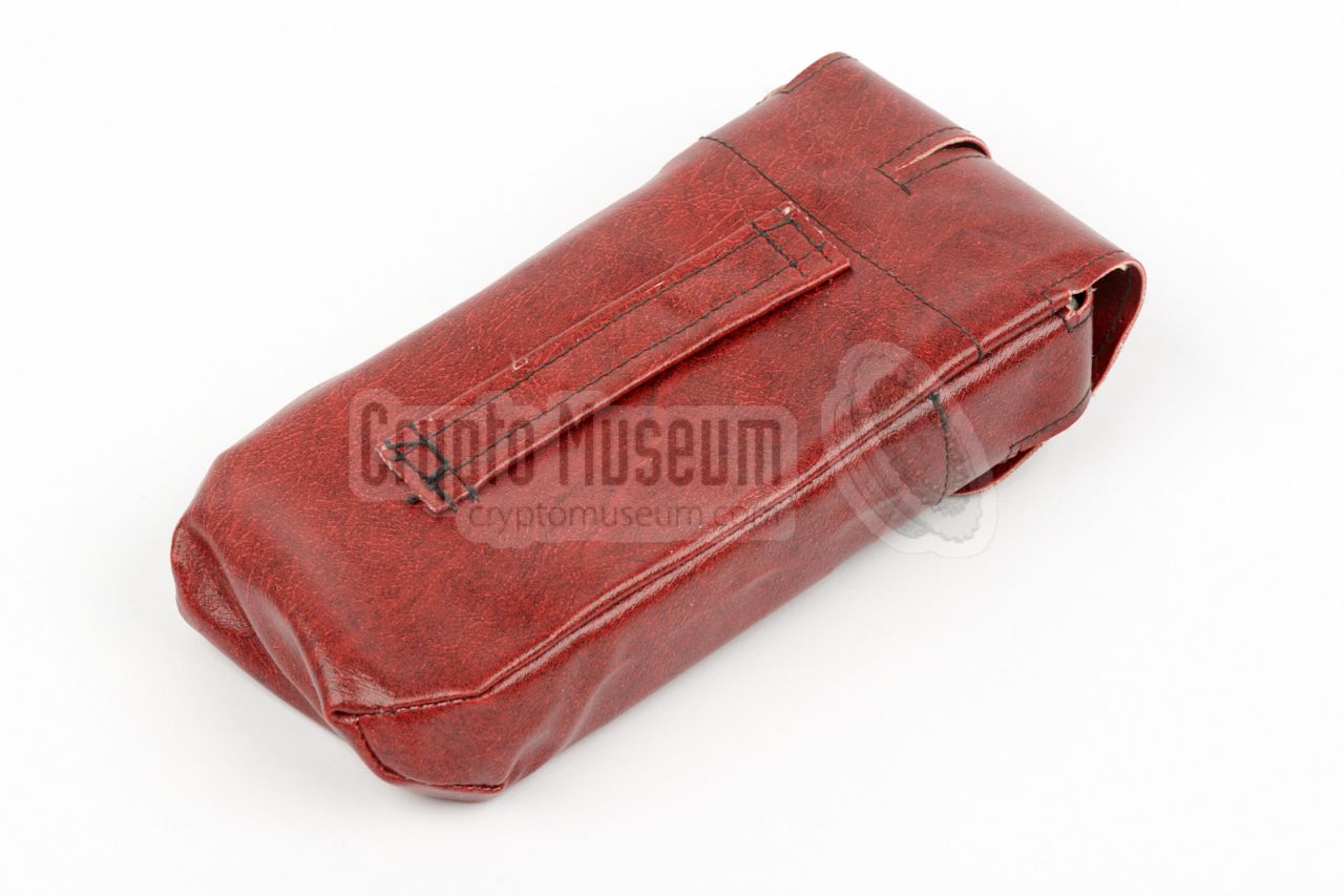
Especially for carrying MEZON on the belt, a soft leather carrying case,
or pouch, was supplied. It was available in several colours,
including black and brown/red (as shown here).
The belt can be looped through the
rear side of the carrying case.
When replacing the batteries or swapping the wire spool, the recorder
can be taken from the case,
without the need to remove the case from the belt first.
|
|
|
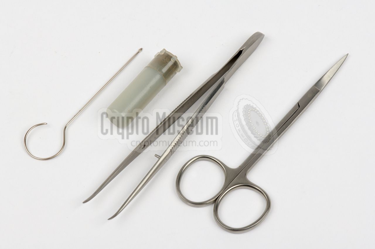
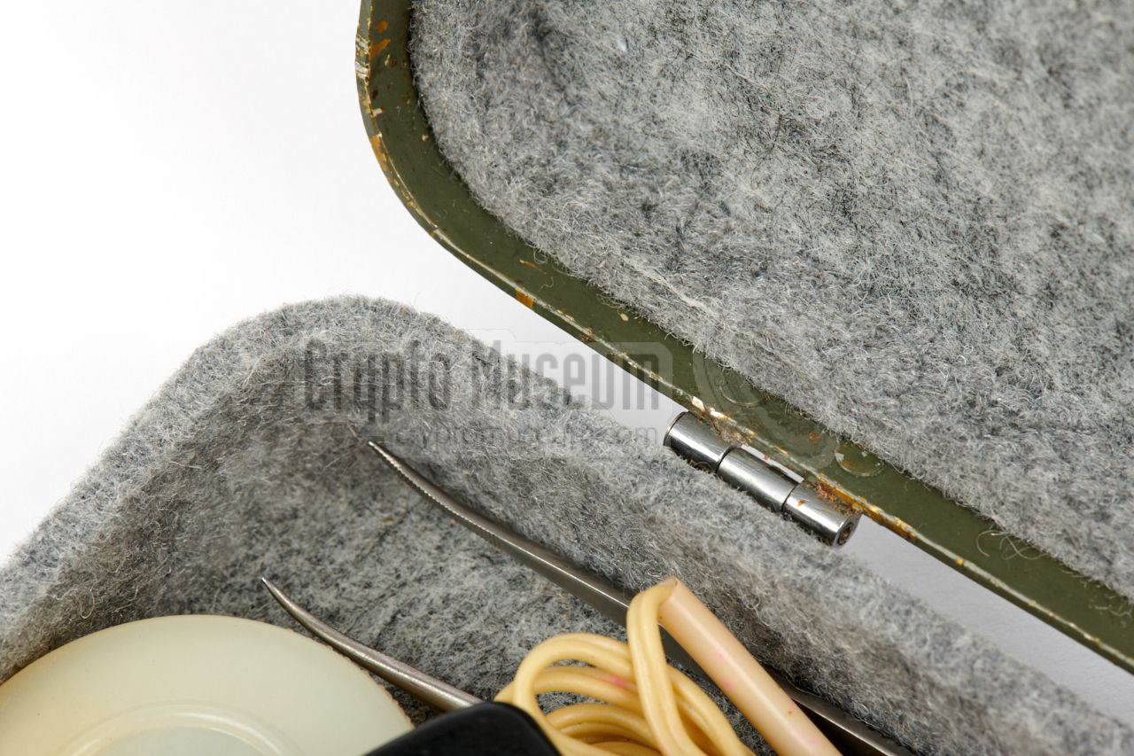
The MEZON kit was supplied with a range of tools and materials to allow
it to be serviced in the field. Tweezers and a pair of scissors were present
to make installation of a wire spool easier, and to allow repair of
a broken wire.
A plastic container with lubricant grease was supplied, along with a
simple application tool.
|
|
|
|
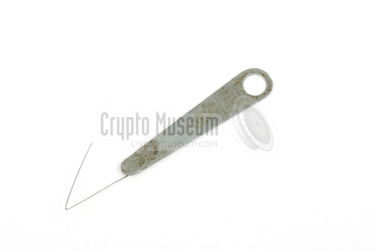
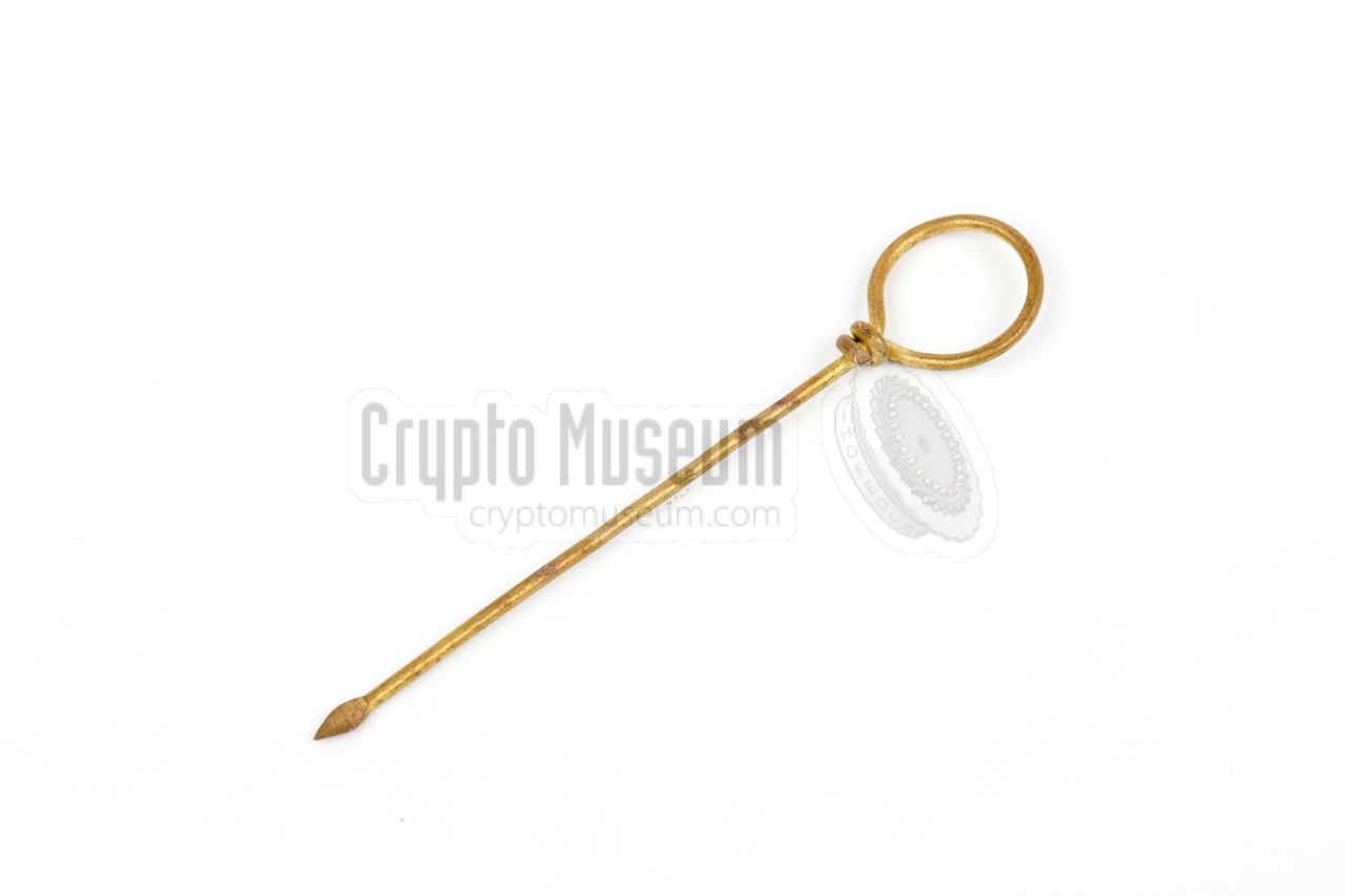
When loading the spools and guiding the wire past the audio head,
a metal grip with a very thin angled steel wire – shown in the image on
the right – was used to handle the extremely thin recording wire.
|
|
|
MEZON came with a small booklet, at approx. A5-size, that acts as a checklist,
but also contains a technical description of the device and and full
operating instructions.
For the technically minded, it also contains the
full circuit diagram of the
recorder, which is built around 5 transistors.
➤ Download the booklet
|
|
|
|
Getting access to the recorder's interior is very straightforward and
requires only the removal of 10 recessed miniature screws from the various
metal panels.
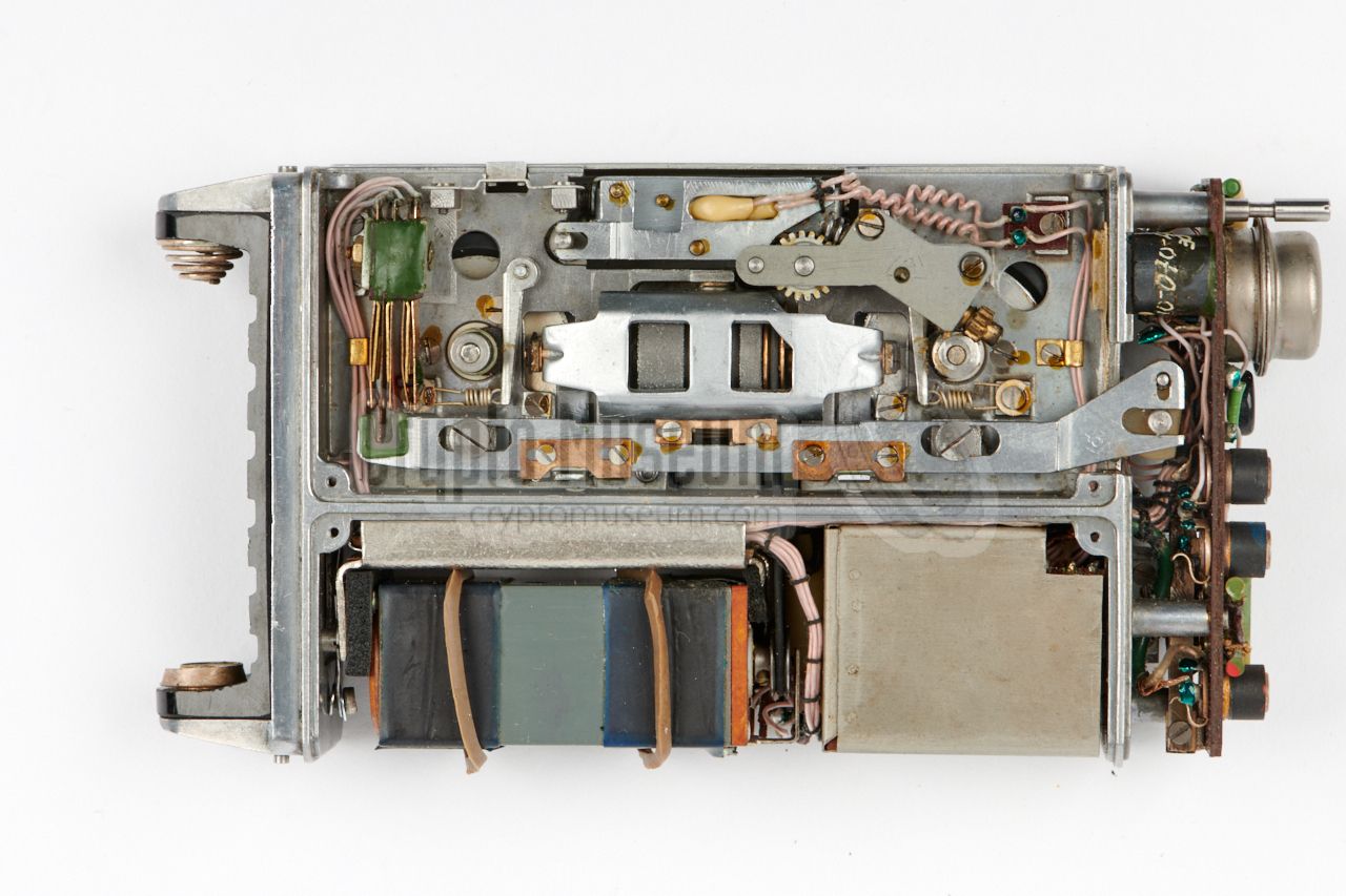
The diagram above shows the various parts of the recorder as seen from
the bottom of the device, after removing the covers.
|
The recorder is build on a die-cast aluminium chassis, covered by a U-shaped
metal panel at the rear, an L-shaped metal panel at the bottom front, and
an arbitrary shaped panel that covers the controls at the
right side of the device.
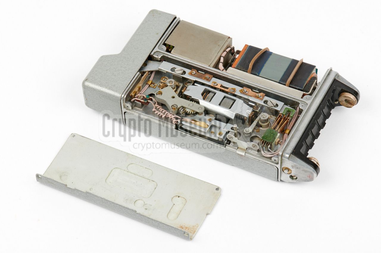
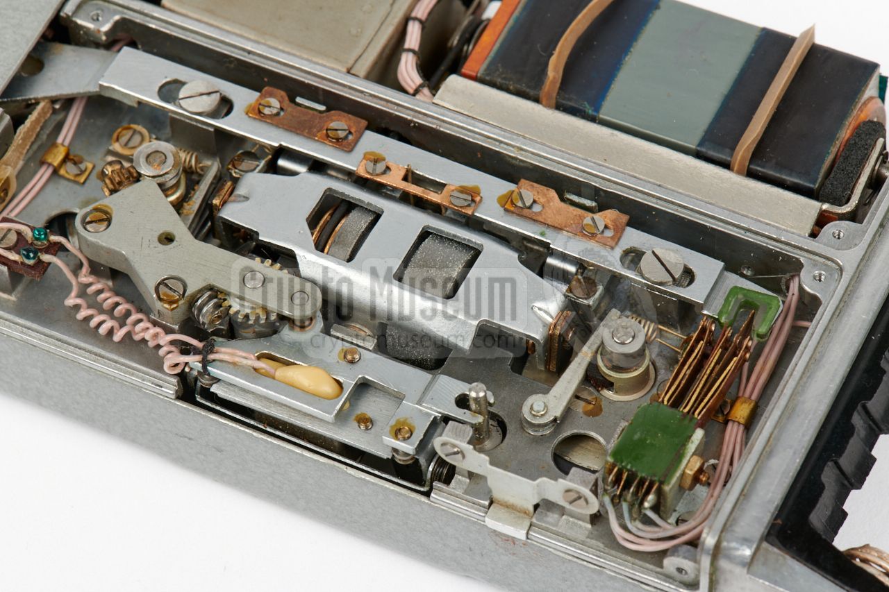
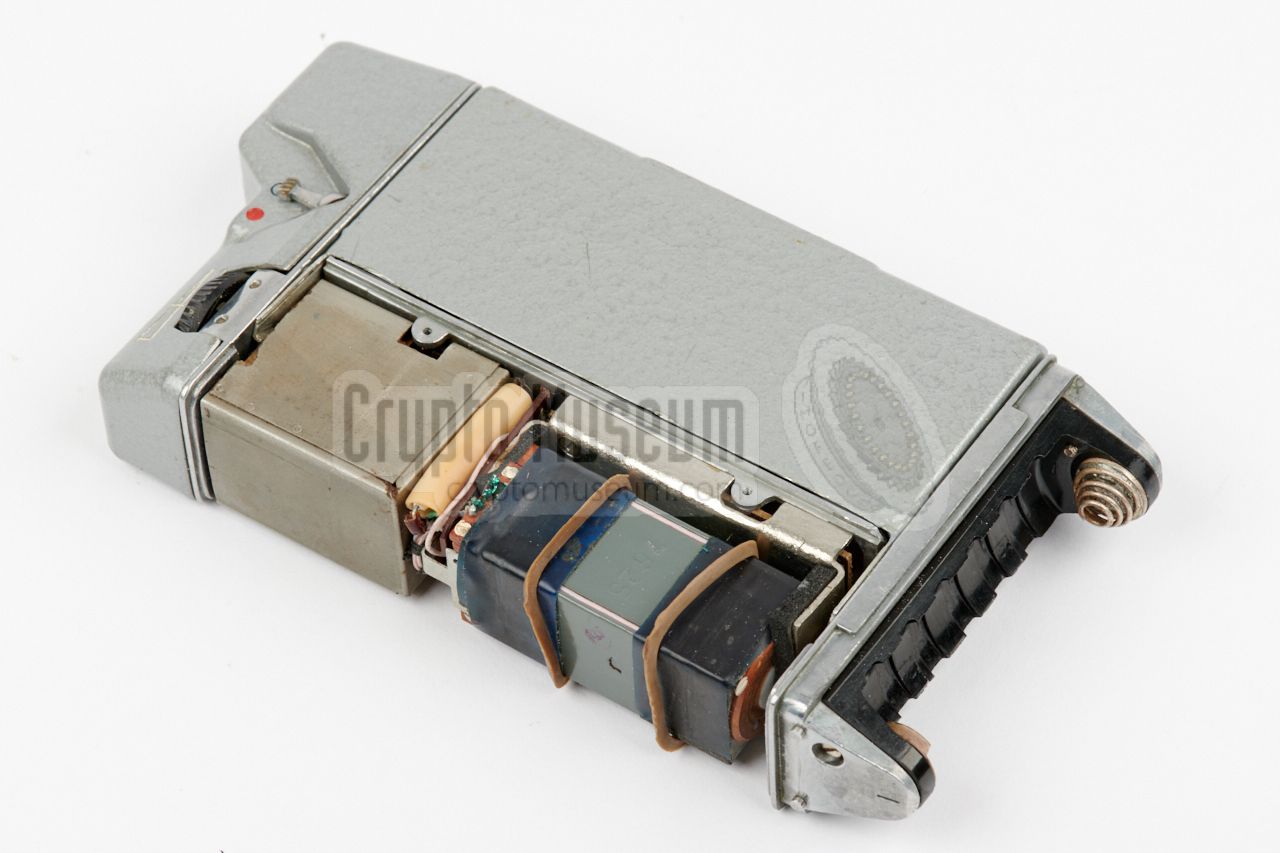
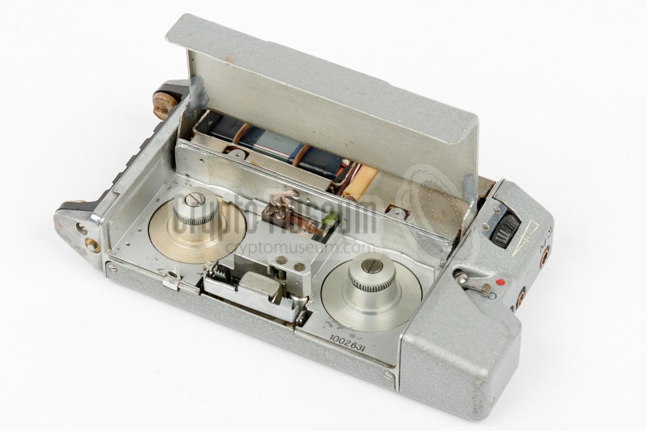
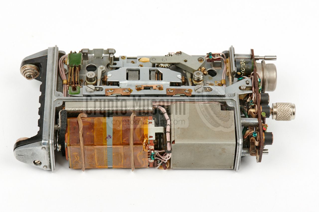
After removing the 10 recessed screws and the metal panels, the interior is
exposed, as shown in the image on the right, where we see the device from the
bottom front. The recording compartment is covered by a hinged lid that is
just visible at the front edge. This grey lid is fixed in place and can not be
removed easily.
|
|
|
|
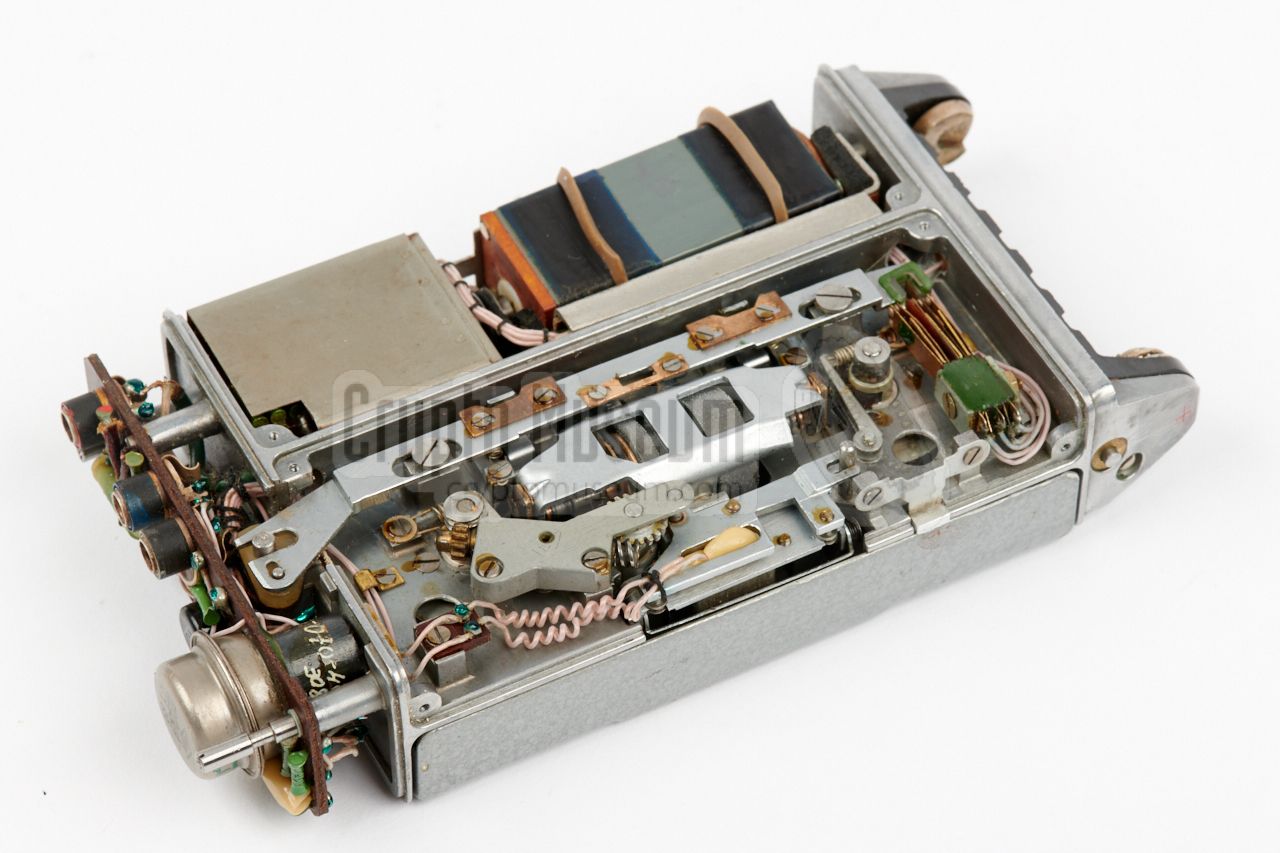
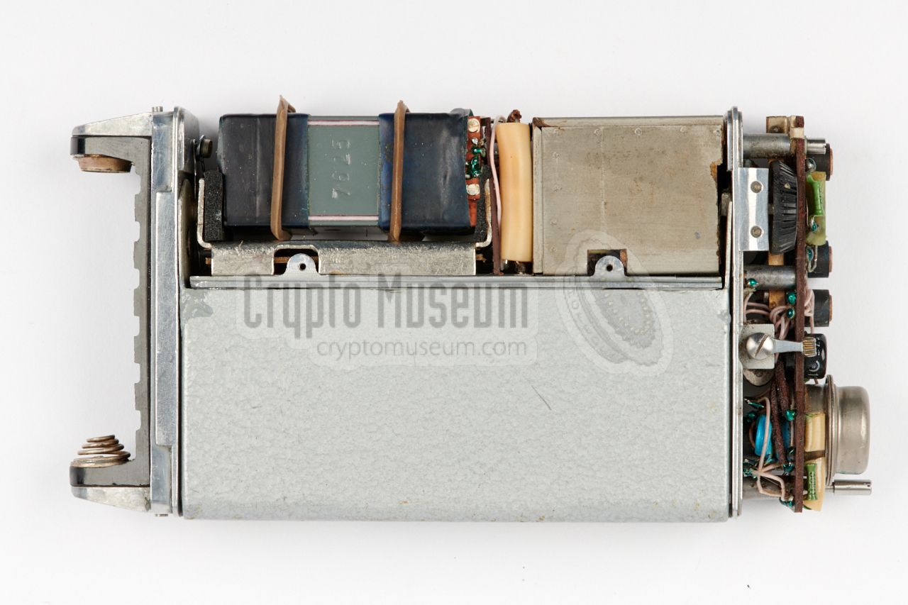
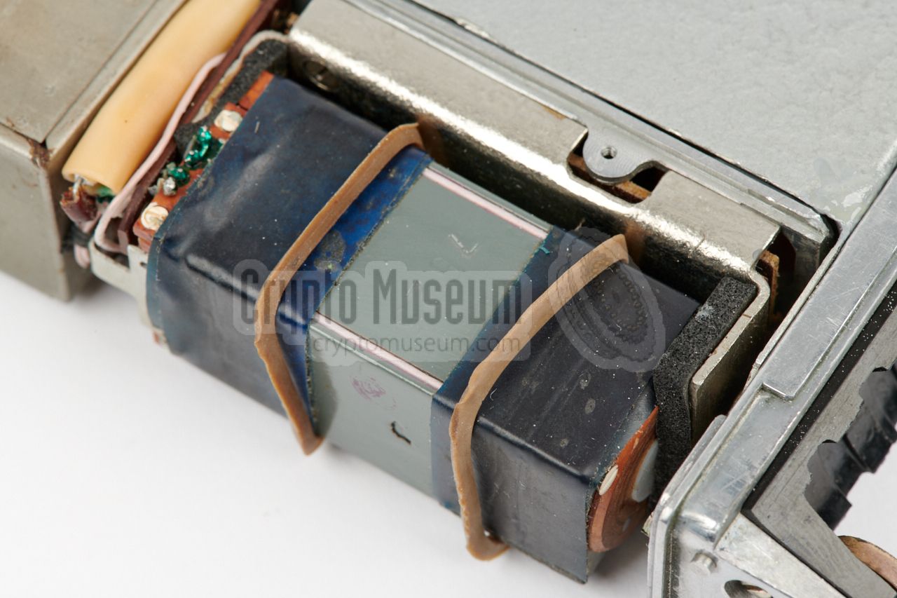
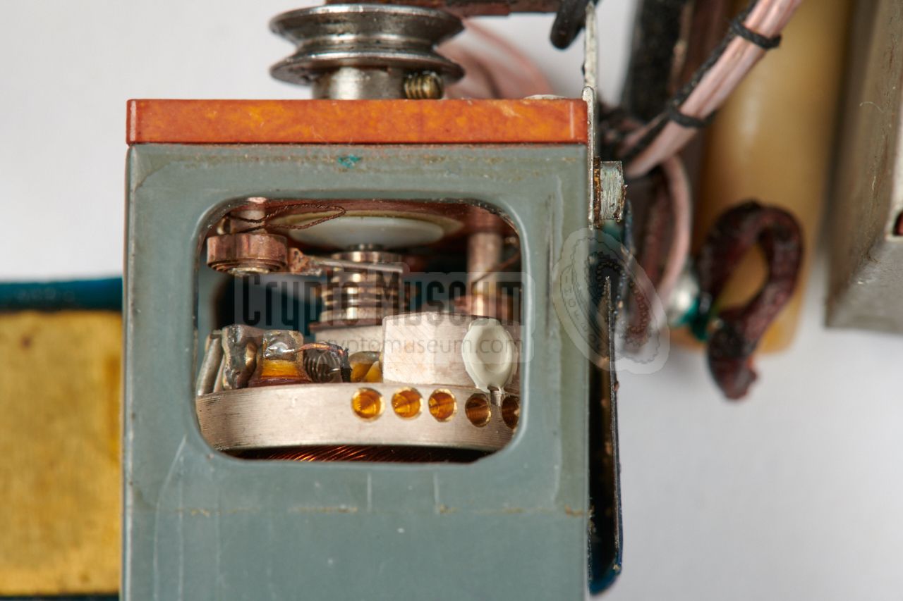
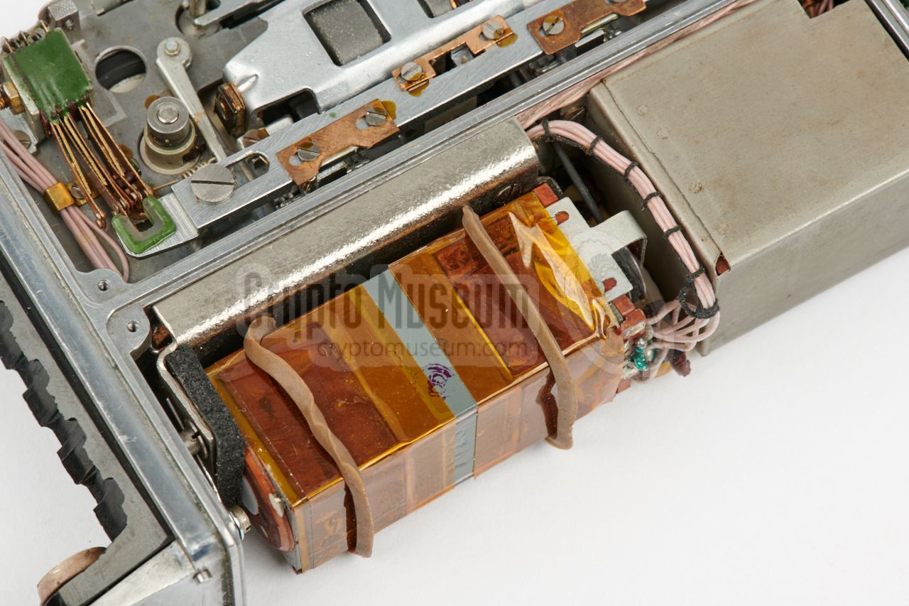
At the rear is the motor that has a
rectangular shape. It is suspended between
two rubber pads and has two rubber bands around its body to reduce the sound
it makes when it is running. The motor has a built-in
centrifugal switch that
is mounted to the axle and acts as the governor. It ensures that the motor
runs with a constant speed. The governor is bypassed when rewinding.
|
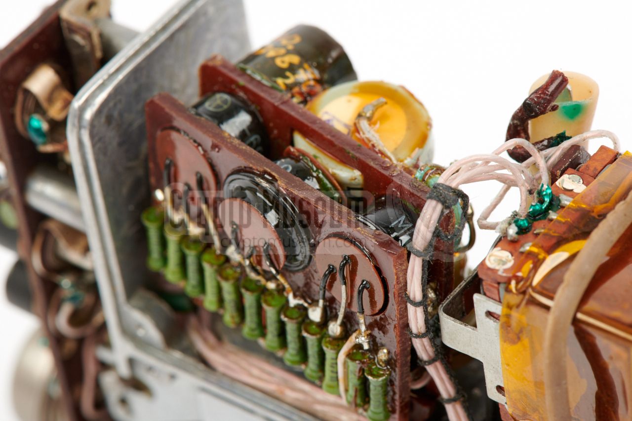
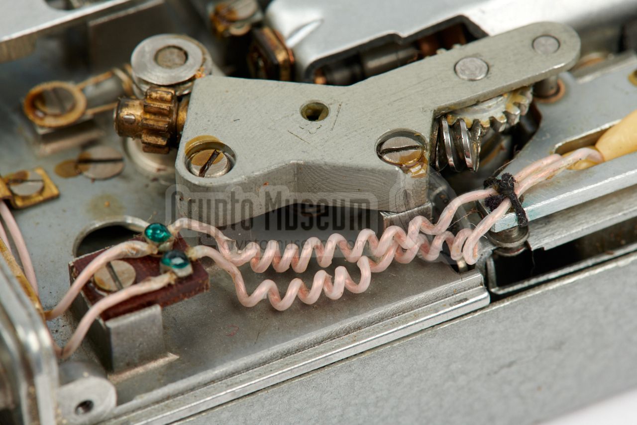
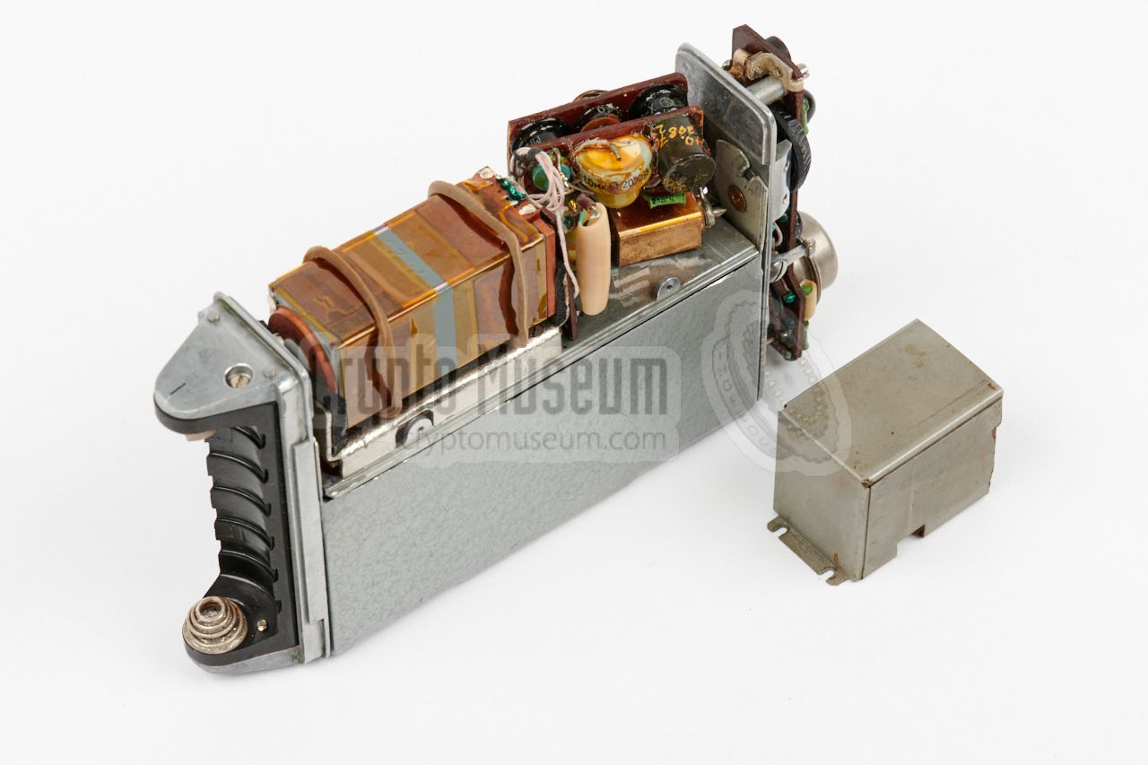
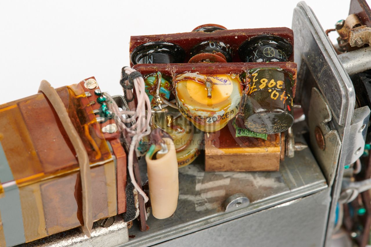
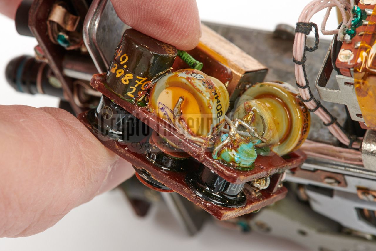
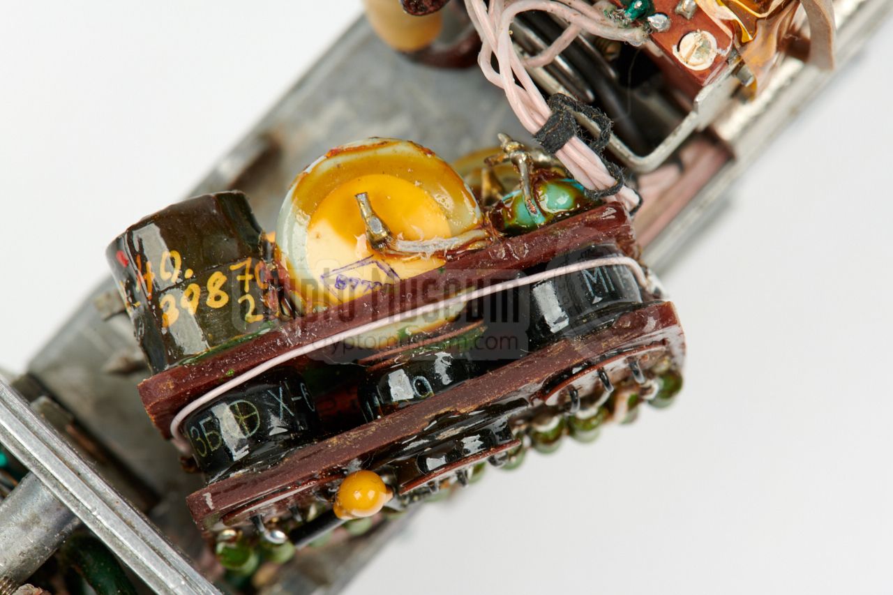
To the left of the motor is the audio amplifier
that is encapsulated in a mu-metal enclosure, in order to reduce
magnetic interference from the motor. The image on the right shows the
audio amplifier after the cover has been removed.
The amplifier consists of two pertinax boards that are strongly glued
together. Each of the board holds a number of parts, some of which are embedded
in the board, whilst others – notably the electrolytic capacitors – are
fitted in between the two boards. The board that is visible in the image, holds
the 3 transistors.
|
|
|
|
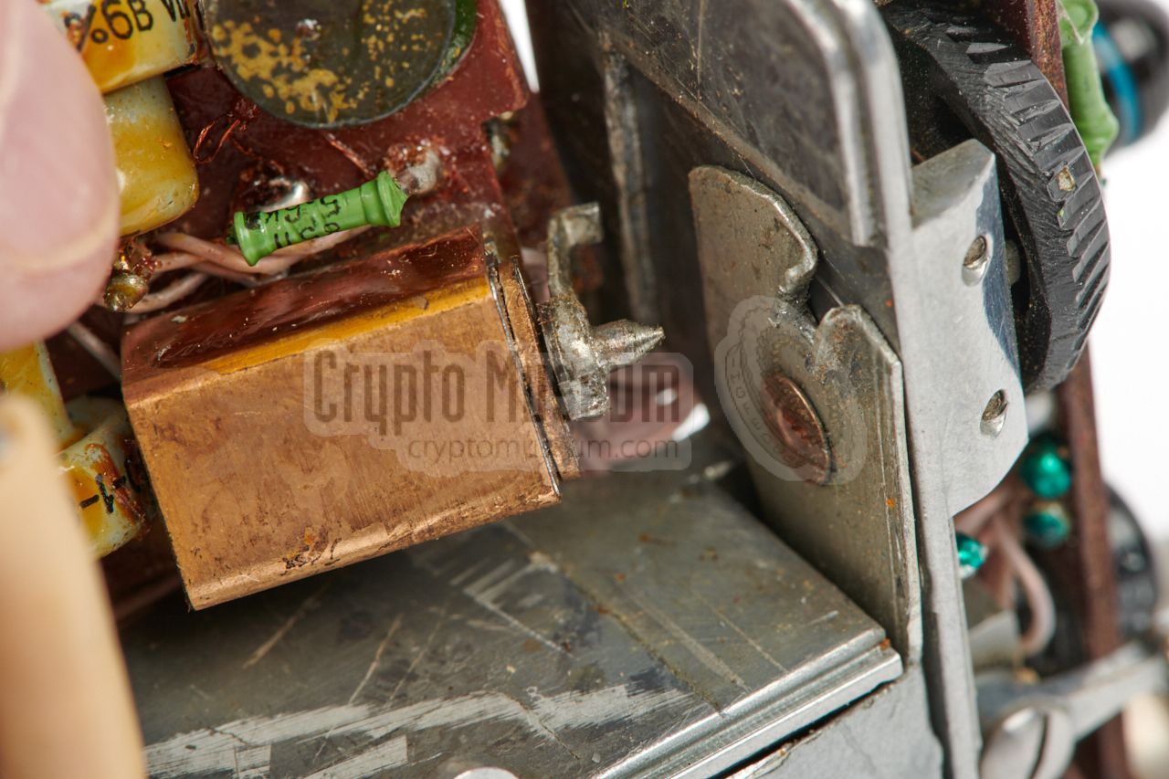
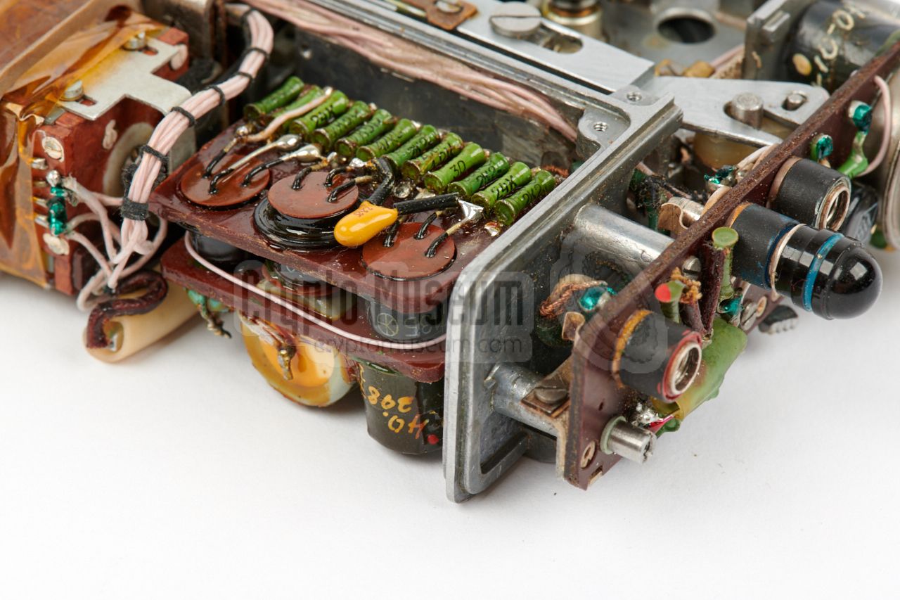
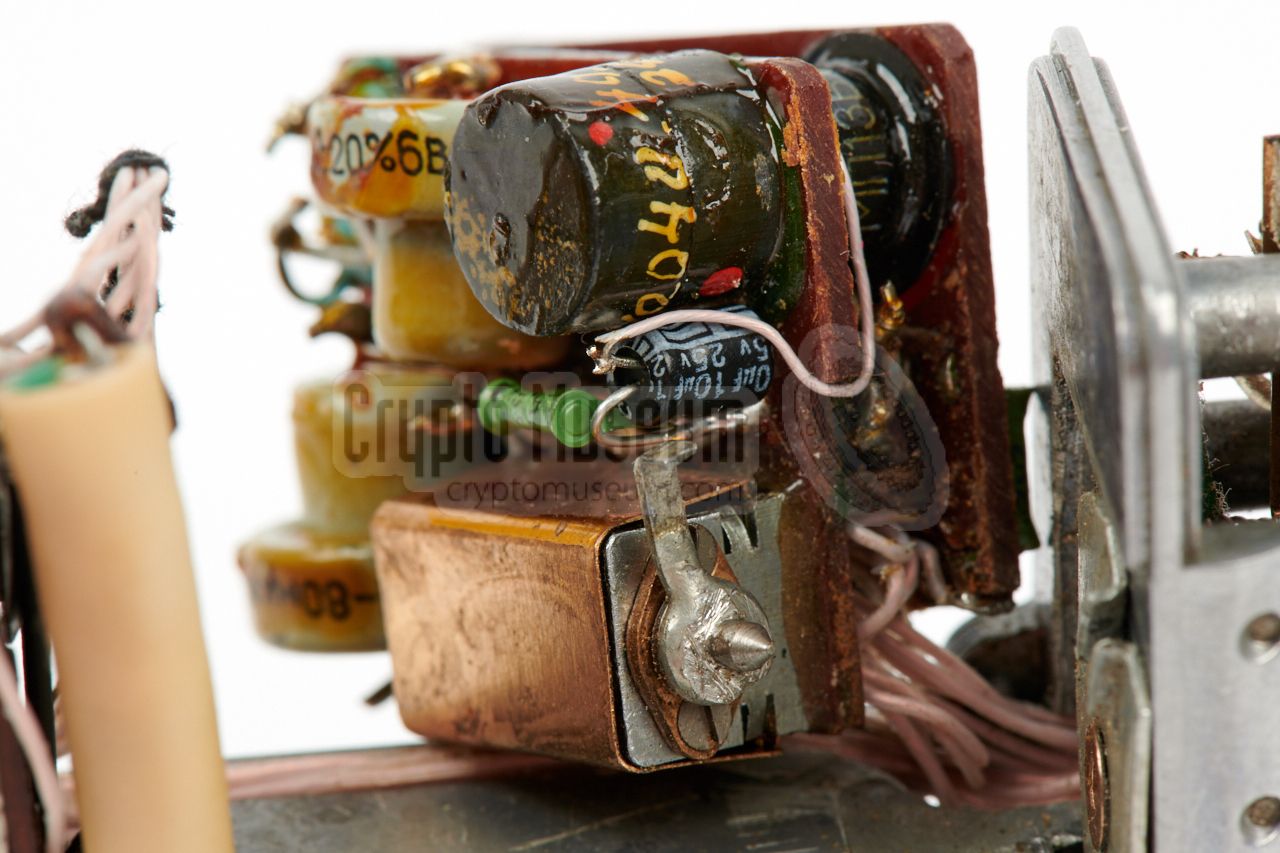
The other side holds the larger components,
such as the 80µF capacitors and an inductor. This side also holds the rather
complex purpose-built 4-pole function switch,
that is used to select between
record and playback. This lever-operated switch is actuated by the hinged
cover. When the cover is open, playback mode is selected. When it is closed,
the device is ready for recording.
|
When the amplifier is broken, it will be difficult to repair. It can not be removed
easily, as it is held in place by its wiring. Furthermore, the circuit
boards are glued together and most of the parts are covered by a strong
conformal coating. More about this in the topic
Restoration.
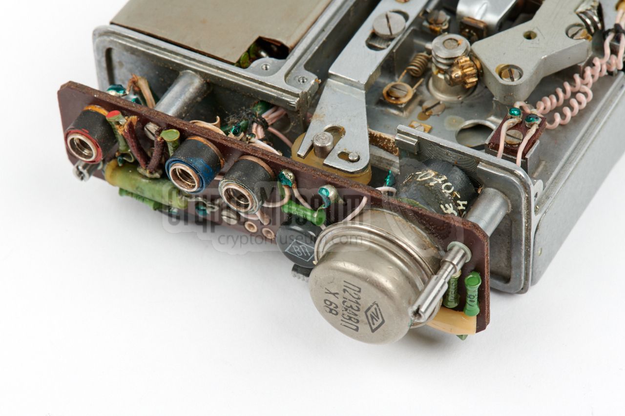
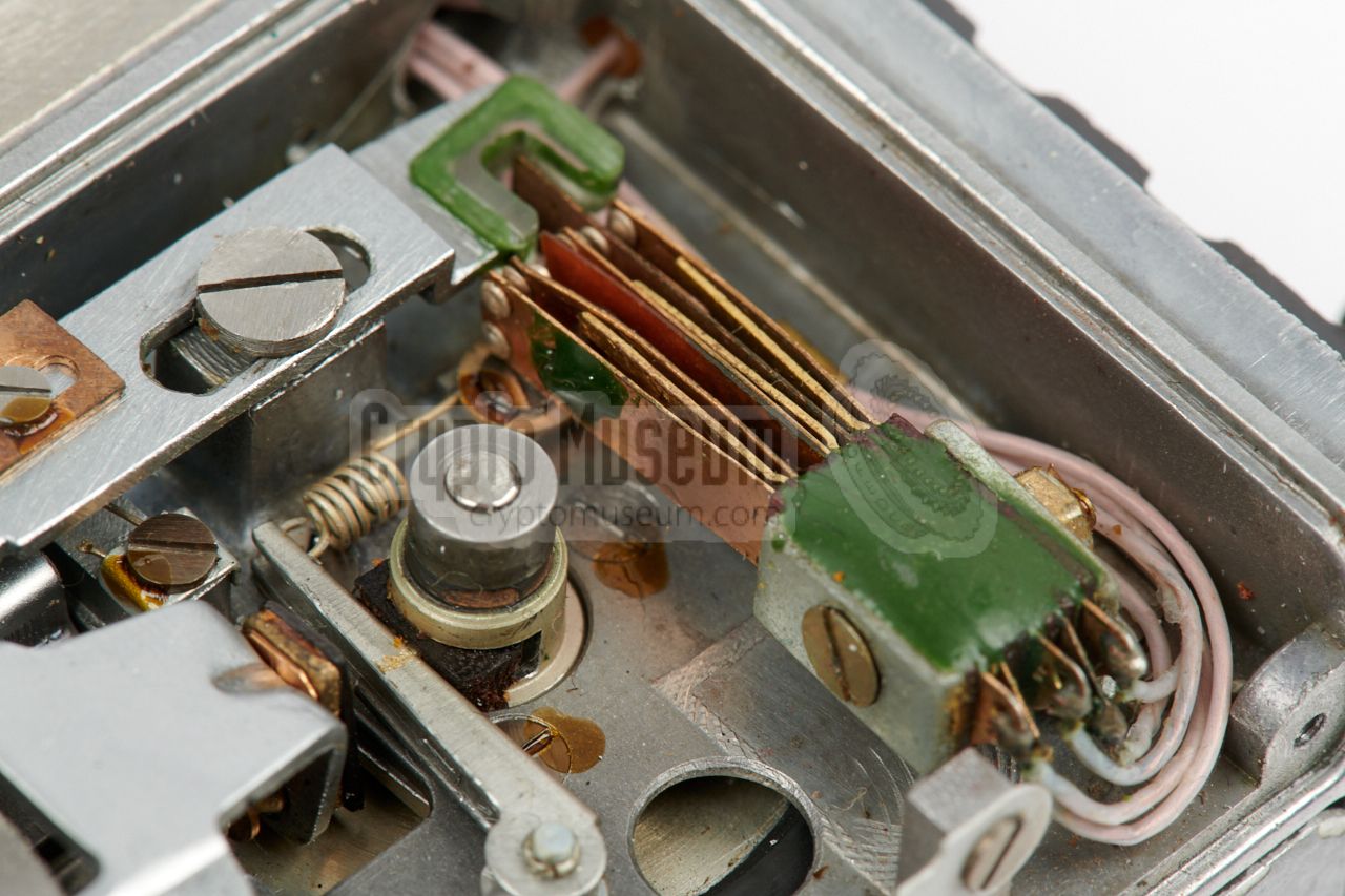
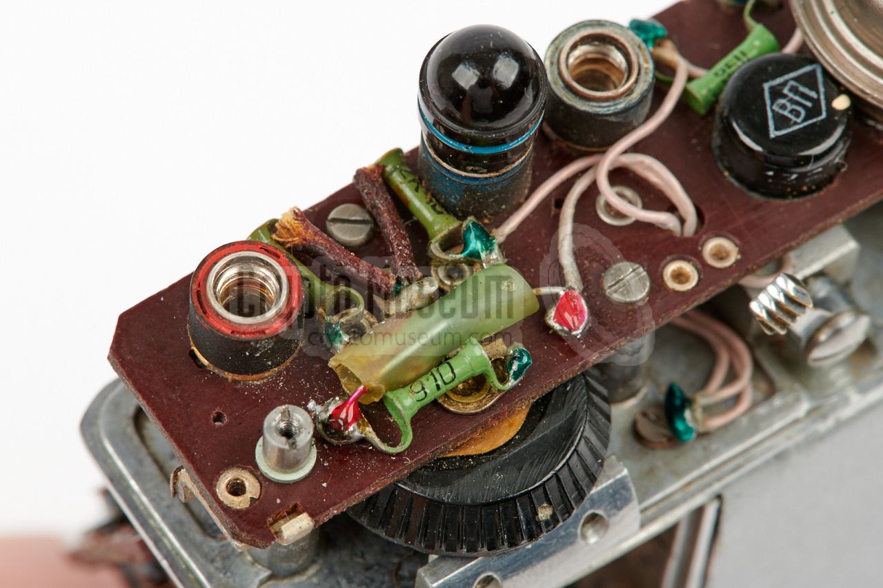
Another pertinax circuit board is present behind the control panel at the right
side of the device. It becomes visible after removing the molded case shell
from the control panel, and is shown in the image on the right. The large
transistor at the right is part of the motor speed regulator.
|
|
|
|
This board also holds a single-transistor oscillator that produces the
bias signal when recording. The inductor of this circuit is visible behind
the big transistor. At the left side of this board are a few components that
are actually part of the amplifier. They are fitted here as the volume
selector switch is also located here. At the upper edge of the board
are the three 3 mm jack sockets.
|
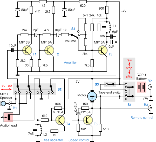
Below is the complete circuit diagram of the recorder. The upper half
shows the audio amplifier, with T1 and T2 as pre-amplifiers and T3 as
the power amplifier (PA). A 3-position volume switch (S4) is present
between T2 and T3. The amplifier is used both for recording and playback,
under control of a 4-pole switch (S2) that is actuated by
the hinged top lid. When recording (rec), the microphone is connected
to the input (T1), whilst the recording head is connected to the output
(T3). At the same time, a bias signal is supplied to the audio head
by the bias oscillator (T4).
When playing back (pb), the audio head is connected to the input, whilst
the output signal is delivered to the microphone 1 (or speaker). In this
position, the bias signal is not supplied to the audio head. At the bottom
right is the motor control circuit (T5), which is basically an electronic
switch that is driven by a centrifugal switch inside the motor. It is
bypassed when rewinding (rew).
There are three 3 mm jack sockets, or busses, marked B1, B2 and B3.
B1 is the socket for the microphone or speaker. B2 controls the power
supply. When using MEZON without connecting the remote control unit
(RCU),
the dummy plug (stub) should be installed in this socket.
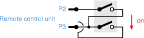
When using MEZON with RCU (shown above),
it should be connected to B2 and B3, in which case B2 controls the power,
whilst B2 controls the motor circuit. The RCU effectively takes over
the function of S1.
|
 |
-
As the NEVA microphone contains a dynamic element, it can be used as
a speaker in playback mode. Alternatively, the earphones can be connected
to this socket when playing back.
|
|
When we received our MEZON recorder, it had several issues.
The left arm of the lid over the wire spools was broken, a suitable
battery was missing and the motor wasn't running when power was applied to
the device. Its restoration took several weeks and is described in more
detail below.
|
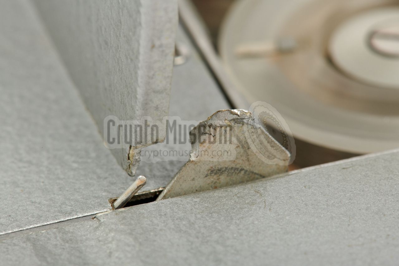
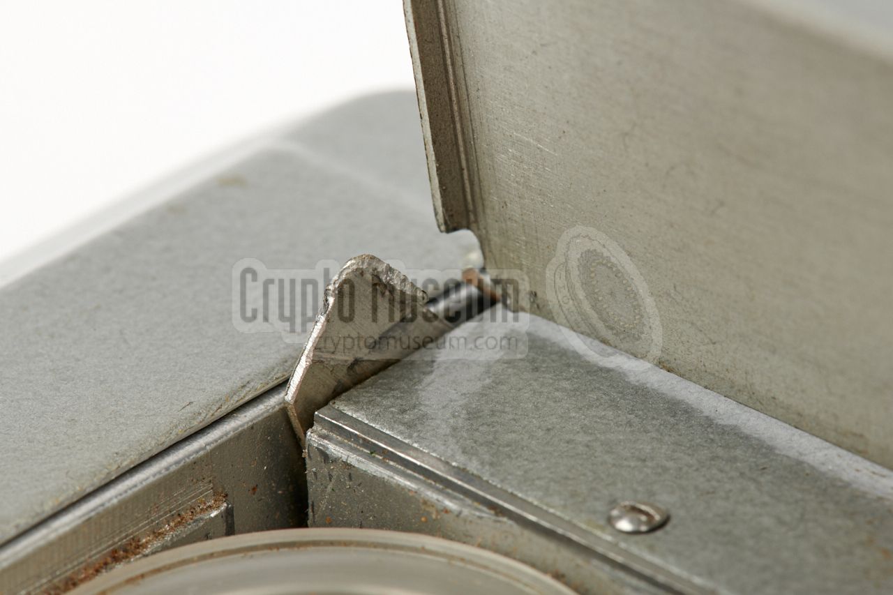
The most obvious problem was the broken arm of the hinged lid over the
wire spools, as shown in the image on the right.
This is actually a weak spot of the device, as the lid
is made of very thin aluminium and the metal spring that keeps the lid in
locked in position, is far too strong.
As a result, too much force has to be applied to the lid when opening it.
This causes the thin area between the lid and the arm to bend and –
after opening and closing it many times – eventually break.
Once broken, it is difficult to repair this, as it can not be removed
from the case frame.
|
|
|
|
Before repair, the (too) strong spring was removed, so that the broken lid
could be positioned correctly without any tension from the spring. The
broken parts were sanded, cleaned, and held in position with a piece of duct tape, in such a way that the lid made a 90° angle with the body.
|
After several failed attempts it was found that the best results were
obtained with a strong two-component metal glue, such as the EPOXY METAL
from Bison [4].
It sticks very well to the metal, but takes several days to fully harden.
The metal glue was applied to the
inside corners of the lid and a thin
extra-hardened steel pin was embedded in the glue to add extra strength.
Although the right arm was still intact, the same repair was applied there,
as it was beginning to show the signs of a future crack. The metal glue
was then left to fully harden for several days.
|
|
|
|
Once the glue was strong enough, the outside of the left arm was repaired
in the same manner, by applying a small layer of metal glue over the crack.
Again, it was left for several days to fully harden. After that, any excess
glue was milled off and the
repaired area was repainted in grey.
|
The results of the repair can be seen in the images below. A weaker spring was
made to replace the old one. It was installed in the motor compartment,
and works as expected.
The next thing to try was to apply a 7.3V DC 1 power source to the battery
terminals to see if the motor would run. Unfortunately this was not the case
as the motor bearings had dried out after several years of storage.
Luckily, this was easier to fix than expected. After removing the blue tape
from the square body of the motor, its interior and the bearings
could be accessed.
|
|
|
|
After applying a tiny drop of lubricant to the bearings, the motor started
spinning straight away. The motor was then re-assembled, but the worn-out
blue PVC tape was replaced by Maylar tape, which is more robust, temperature
proof and sustainable, as it does not disintegrate over time.
|
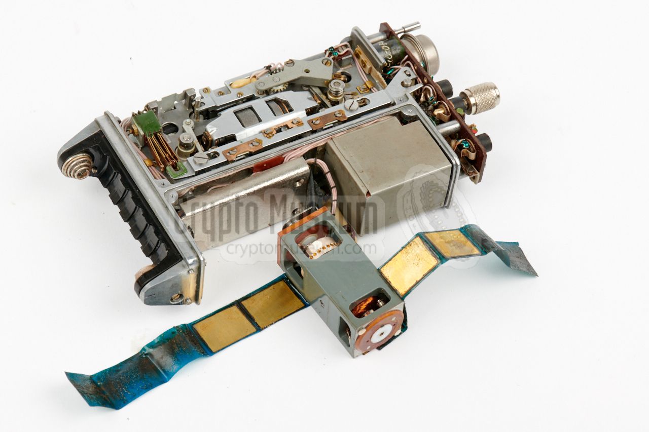
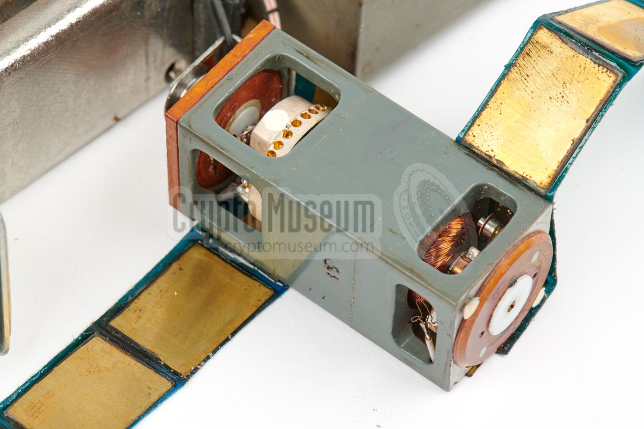
Note the rectanglular brass shields that are held in place by the tape.
They are used to cover the rectangular holes in the motor's frame
and are necessary to reduce interference in the amplifier.
The image on the right shows the reworked motor re-installed in its bay
at the rear side of the machine. The rubber bands are needed to reduce
the sound of the spinning motor, which is particularly important for
covert recordings.
And after cleaning the driving gear and the rubber
pads of the pick-up and supply reels, the wire and the spools are properly
driven again.
|
|
|
|
Next, it was time to check the amplifier. Unfortunately, this part was not working as expected. In fact, it was not working at all. Although very
faint cracks can be heard when altering the volume setting, no sound or noise
from the audio head was heard at all, when playing back a recording.
|
As the amplifier is also used for recording, it was assumed that recording
wasn't possible either. In order to address this problem, the metal cover
has to be removed from the amplifier section.
The image on the right shows the amplifier after the metal cover has been
removed. It consists of two pertinax board that are bonded together.
Unfortunately, it is very difficult to remove the amplifier, as the teflon
wires that connect it to the rest of the device, are very short. Using the
circuit diagram and an external amplifier it was discovered that all
coupling capacitor were dead.
|
|
|
|
As these capacitors are not easily accessible – they are glued-in between
the two boards – it was decided to connect modern alternatives in
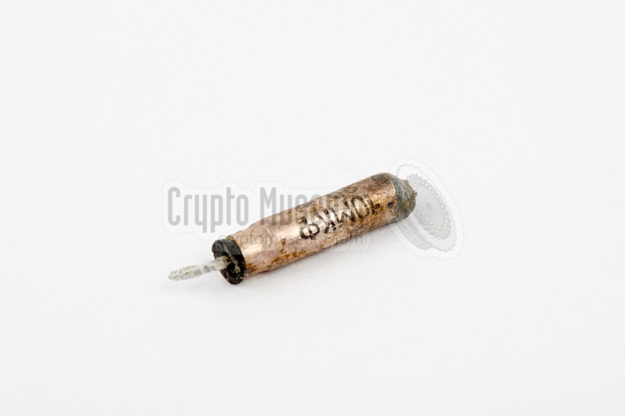
parallel to the old ones. The 6µF capacitor near T3, was
replaced by a miniature 10µF alternative
that was fitted aside the REC/PB function switch.
|
It was connected to the collector of T3 with a
thin teflon wire, similar to
the ones that are used in the rest of the circuit. In the same vein, the
2.2µF capacitor between T1 and T2 was replaced by a small tantalium type,
as shown here. It is connected directly to the wiring of T1 and T2.
The third capacitor that had to be replaced, was the 10µF one between T2 an
T3. Luckily, as it is connected in series with the volume control (S4), it
is not part of the miniature circuit. Instead it is fitted externally, on
the small PCB behind the control panel, close to the volume selector (S4).
|
|
|
The adapter cable that is used for connecting an external audio source
or an external amplifier, was also broken. Excessive solder inside the
jack plug caused a full short-circuit
of the audio line. This should be regarded as a manufacturing fault,
with was easily fixed with a bit of rework.
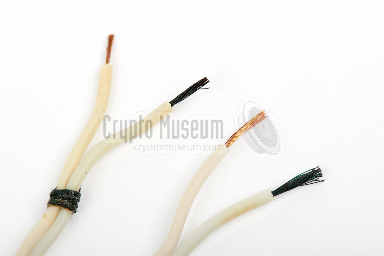
The SHUNT-adapter,
used for connecting MEZON to an external 7V power source,
wasn't working either. This was caused by one of the two wires (inside
the white cable) that was heavily corroded over the entire length
and was not conducting anymore, probably due to the use of acid flux.
|
|
|
|
Looking at the picture above more closely, we can see that the
corroded wire even shines through the plastic insulation.
As the cable was beyond repair, it was replaced by
a similar plastic cable, from an old Soviet work light. The engraved
aluminium ID tags on the wires, were removed from the old cable and
refitted on the new one. The SHUNT was
cleaned and refitted to the new cable.
|
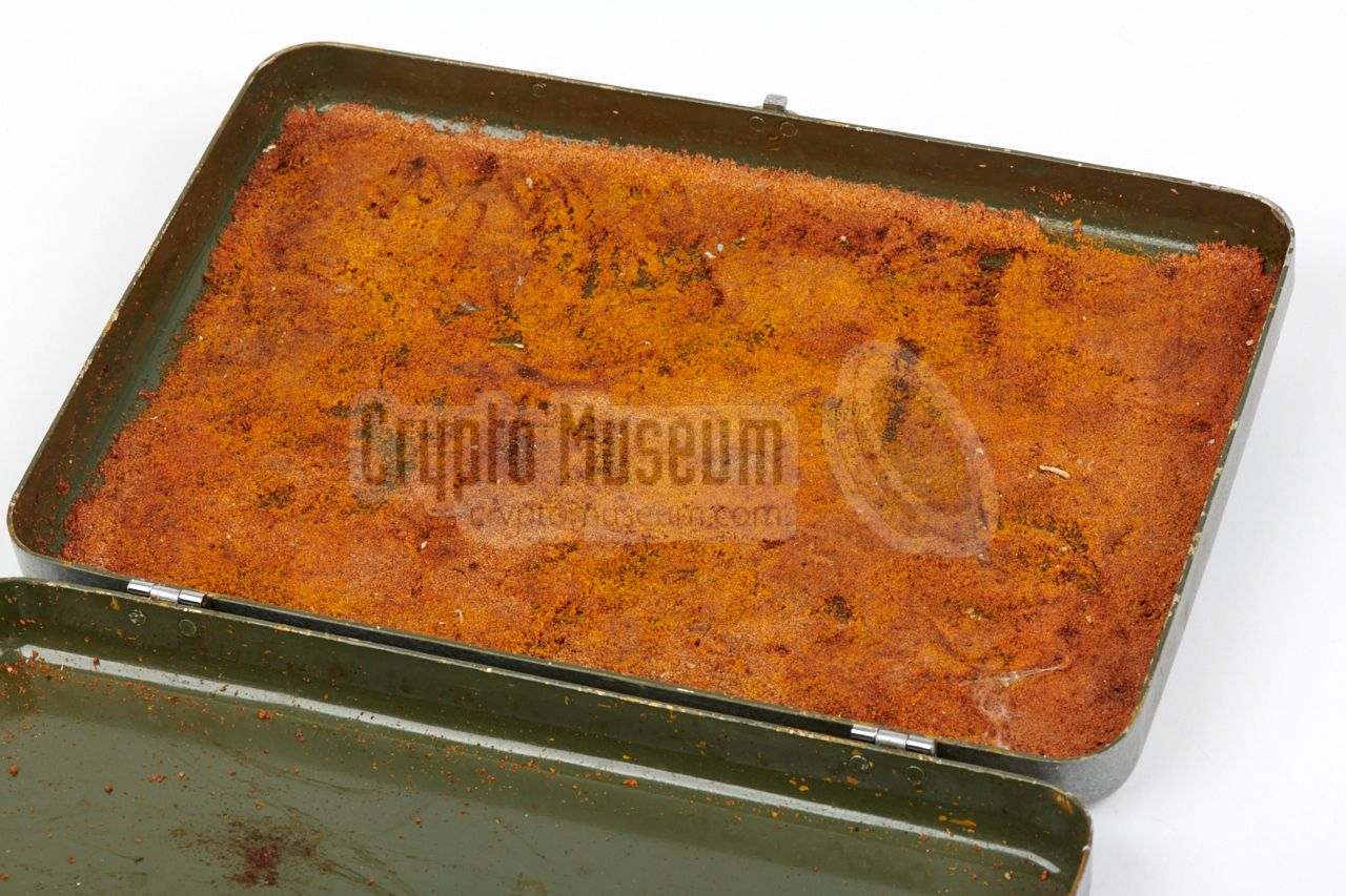
The yellow foam inside the storage case had disintegrated completely
and had become sticky, to the point where its residues had started to cause
damage to the parts stored inside the case. This means that it had to be
removed. Furthermore, the white pre-shaped polystyrene, with cut-outs
for the various parts, was missing completely and had probably been trown away
earlier in life.
It was decided not to recreate the interior of the boxes – it would deteriorate
again anyway – but instead replace it with something more practical that would
still be suitable for the Cold War era.
|
|
|
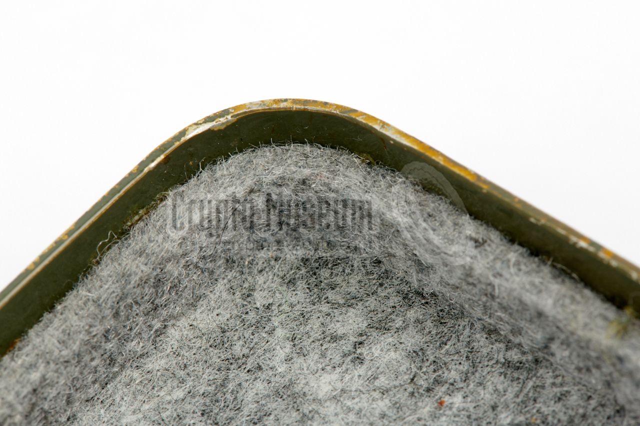
The interior of the metal box was cleaned and the remains of the foam and its
glue were carefully removed. Next the inside of the lid, the bottom and the
sides were covered with 5 mm thick grey felt,
as shown in the images above. Vertical
dividers were added to keep everything in place.
The following has been repaired so far:
|
- Left arm of top lid repaired
- Motor repaired
- Amplifier repaired
- Belt and drive gear cleaned
- Drive rubbers cleaned
- Eraser repaired
- External audio adapter repaired (short circuit)
- Storage case interior renewed
- Cable of SHUNT-adapter replaced
|
-
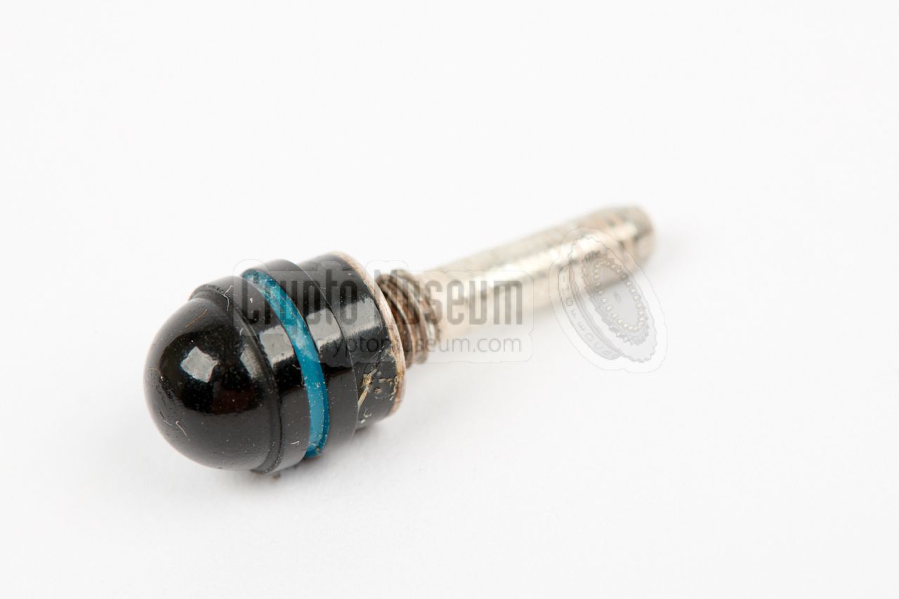
Note that the shorting plug, or stub,
has to be installed in the middle jack socket, in order to run the device
without the remote control unit. Without the stub or the
remote control, the device will not work.
|
|
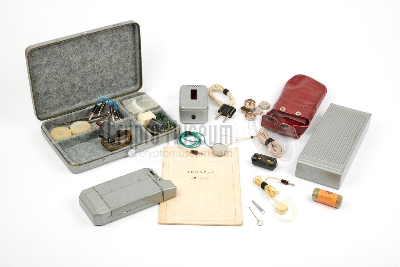
Below is a list of items that were originally supplied with each Mezon
wire recorder, as printed in the first chapter of the original
operating instructions.
The items listed in red are currently missing from our collection.
Any help in obtaining them would be greatly appreciated.
|
|
All items came in two metal boxes: a low one (box 1) and a higher one (box 2).
The latter (box 2) is currently missing from our collection. Furthermore, we
have altered the interior of box one, as the original foam had disintegrated
completely. The images below shows an original MEZON kit with the original
papers, from the collection of the
KGB Spy Museum
in Lithuania [1].
|
|
We are currently looking for the following items:
|
- 3 mm jacks with 4 mm locking thread (several pieces)
- High metal storage case (box 2)
- Oil container
- Screwdriver
- Head cleaning device
|
-
Document kindly supplied by Detlev Vreisleben [5].
|
|
|
|
Any links shown in red are currently unavailable.
If you like the information on this website, why not make a donation?
© Crypto Museum. Created: Friday 24 November 2017. Last changed: Wednesday, 05 November 2025 - 11:46 CET.
|
|

|
|
|


![MEZON kit in the collection of the KGB Spy Museum [1] Complete set](img/302778/026/thumbnail.jpg "image # 302778/026")
![MEZON kit in the collection of the KGB Spy Museum [1] Storage case #1](img/302778/028/thumbnail.jpg "image # 302778/028")
![MEZON kit in the collection of the KGB Spy Museum [1] Storage case #2](img/302778/027/thumbnail.jpg "image # 302778/027")
![MEZON kit in the collection of the KGB Spy Museum [1] Storage case #2](img/302778/029/thumbnail.jpg "image # 302778/029")
![MEZON kit in the collection of the KGB Spy Museum [1] Complete set](img/302778/026/full.jpg)
![MEZON kit in the collection of the KGB Spy Museum [1] Storage case #1](img/302778/028/full.jpg)
![MEZON kit in the collection of the KGB Spy Museum [1] Storage case #2](img/302778/027/full.jpg)
![MEZON kit in the collection of the KGB Spy Museum [1] Storage case #2](img/302778/029/full.jpg)