|
|
|
|
|

|
|
Opto Voice ZEISS Stasi JO-4.01 → ← Dahme 2
The kit consists of two optical transceivers,
each of which is installed at one end of a free-space communication path
in the line-of-sight (LOS).
Each device contains an transmitter and receiver, and uses a patented
double-mirror system [4] to guide the narrow parallel infrared beam from one
device to the other. As the viewing angle of the mirrors is very narrow (0.38°),
the devices must be accurately aligned using the built-in range scope.
This way, the device was virtually undetectable and allowed agents to deliver
a message without physically crossing the border.
|
|
|
|
The device was introduced in 1974 as the successor to the earlier devices
Dahme I and Dahme II, which in
turn were inspired by the American XE-2 that had been
confiscated by the Stasi in 1959.
The technology was used by the Stasi for cross-border communication with
its agents in the free West, and had been improved over the years, to the point
where it had a range of several km.
In November 1984, a JO-4 was
confiscated by the West-German authorities
and shown in the press.
|
-
The Dahme is a river that flows in the German states of Brandenburg
and Berlin. The Stasi commonly used river names for its infrared
(IR) communication devices. As Dahme is pronounced the same as the
German word Dame (lady), the name was easily transformed into Kleine Dame
(little lady).
|
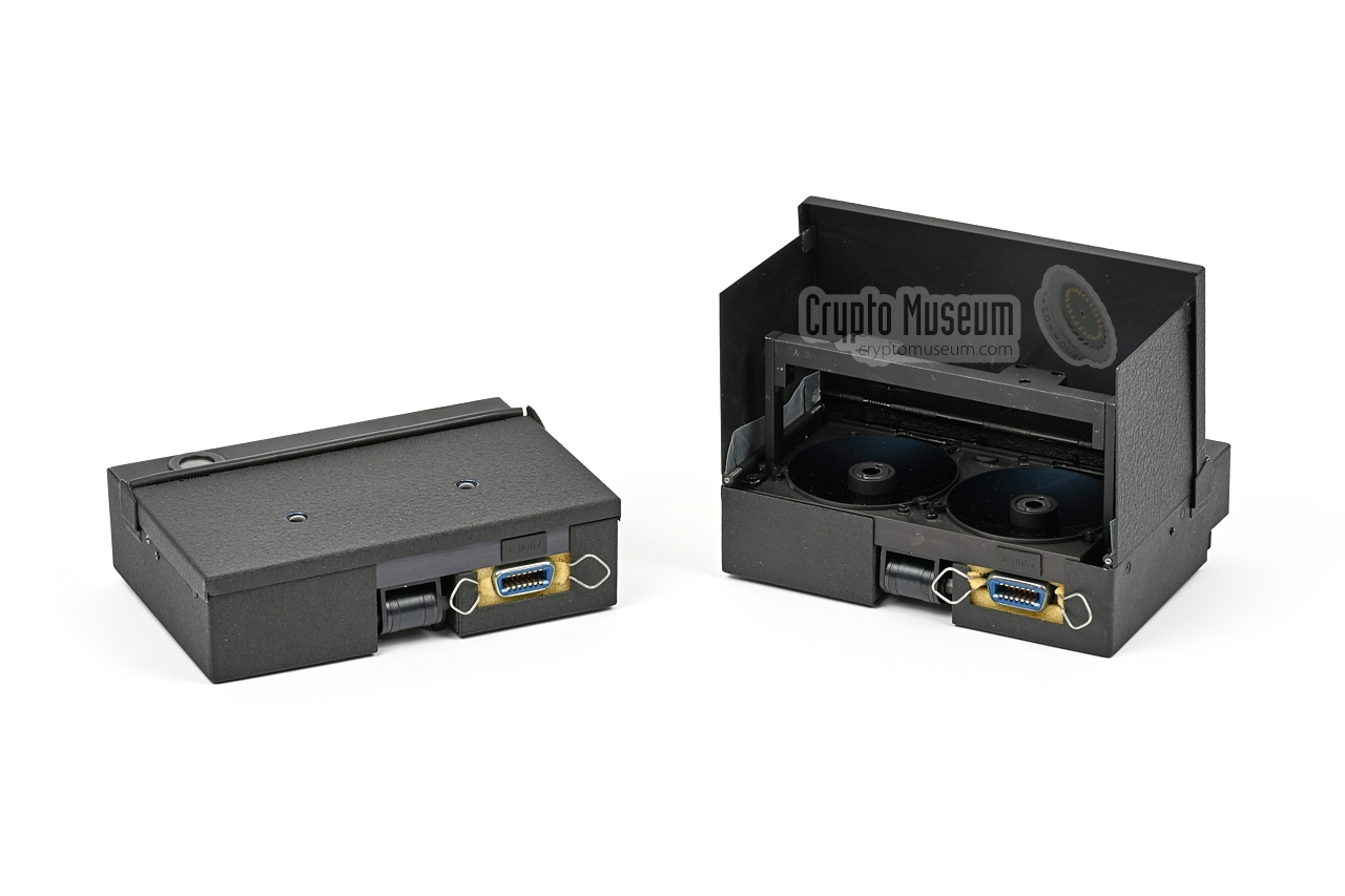
The diagram below shows two different versions of the JO-4,
which in this case were part of the same set (i.e. they have the same
serial number. At the right is the regular version,
which has two large parabolic mirrors
— the primary mirrors — and two
smaller ones that are mounted on a movable bar
— the secondary mirrors.
At the left is the lens-version of the
device (see below).
At the bottom of each device is a
14-pin Amphenol socket to which the
handset is connected. The unit is powered by an external
4.5V DC source, that must be connected to the LEMO-socket
on the handset. It can be supplied by the PSU (which is missing
from our set), or the batteries of a portable flashlight.
In the latter case, the supplied power cable must be installed
between the LEMO-socket and the E10 fitting of the flashlight
(from which the lightbulb has been removed).
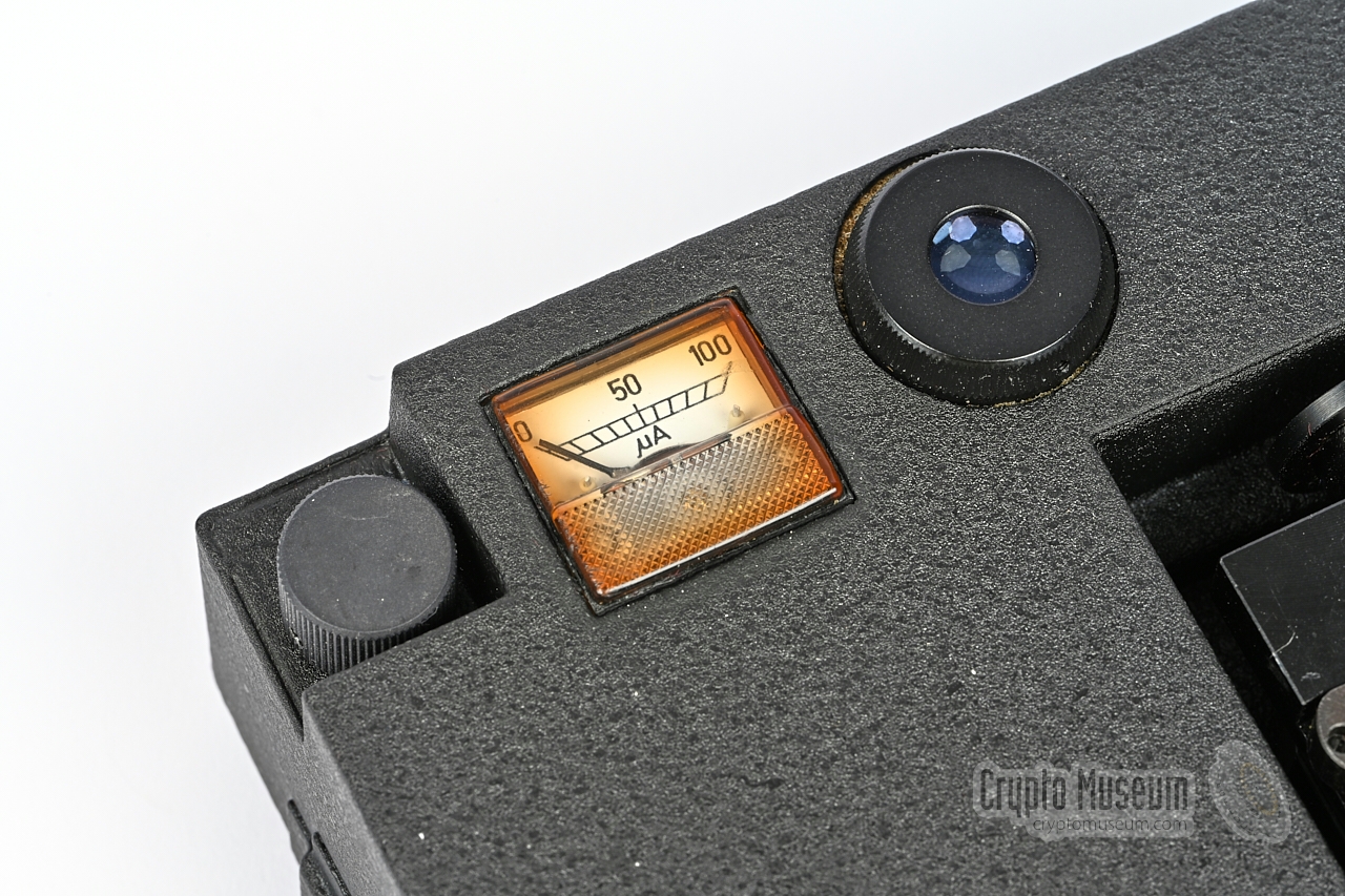
At the rear is a small meter.
When transmitting, the meter shows the modulation level.
In receive mode it shows the battery voltage. To the left of the meter is
a volume knob that controls the audio level of the earpiece, and to its
right is the eyepiece of the built-in viewfinder.
Each device is controlled by a handheld remote control unit
that must be connected to the 14-pin Amphenol socket
at the bottom of each transceiver.
The handset has a built-in microphone and a fixed-wired earpiece.
At the top is a lever-operated MODE-selector with three positions:
receive (centre), transmit & receive (left) and tape input (right).
At the bottom of the handset are two sockets: one for
connection the 4.5V DC power, and one for connection of
external audio devices.
|
- Transmit & receive (microphone & tape player)
- Receive only
- Transmit & receive (tape player only)
|
-
Note that this is different from the modes described in the retrieved
documentation [A][B].
The documentation describes an early prototype, which is different from
the final design.
|
The block diagram below shows the basic setup of the JO-4. A complete system
consists of two units known as (1) and (2), each of which is placed at one end
of a free-space transmission path. Note that a direct line-of-sight (LOS)
between the two units is mandatory. The opening angle is very narrow (0.38°),
so use the viewfinders at both ends to ensure that the devices can
'see' each other properly. When correctly adjusted, a distance of 3
kilometres or more should be feasible.
|
| |
Basic full-duplex setup with flashlight-powered units
|
Both units are powered externally, as the devices have no provision for
interal batteries. In most situations, the 4.5V power was supplied by
a 3-battery flashlight that had to be (partly) dismantled.
Alternatively, the units could be powered by an external mains power supply
unit (PSU), but only one such PSU was supplied with the kit (and is
missing from the kit in our collection).
|
In the advanced setup, the remote system (1) is battery powered, whilst the
local system (2) is powered by the mains power supply unit (PSU) (4),
via the supplied expansion unit (3).
The PSU can also be powered by a 12V DC source.
This situation is shown below. Note that the Expansion Unit (3) is connected
between remote control unit (2) (the handset) and the local transceiver (2).
|
| |
Advanced setup with external power and recording facility
|
In this setup, normal full-duplex voice transmissions are possible, just as
in the basic setup. But it is also possible to use the local system (2)
as an unmanned auto-recording station. It allows the voice transmissions from
the remote station (1) to be recorded onto an external UHER recorder.
In this configuration, the local station (2) can be used as an
electronic dead letter box (EDLB).
It allowed an agent to deliver his message without the need to establish
a two-way contact first.
Automatic recording is possible by the virtue of a 16 kHz pilot tone,
transmitted by both units. 1
It activates a recorder
that is connected to the expansion unit (3). Apart from the auto-recording
feature, a tape recorder could be connected to the
5-pin DIN socket
of the handset of either unit, either for recording or playback.
It allowed instructions and third-party messages to be passed.
|
 |
-
Both units transmit a 16 kHz pilot tone that can activate the
expansion unit at the other end. Note that this is different from
the later JO-4.03 kit, in which only unit number
(1) transmits a pilot tone. This was done to accomodate the 70 kHz
wideband transfer feature of the JO-4.03.
|
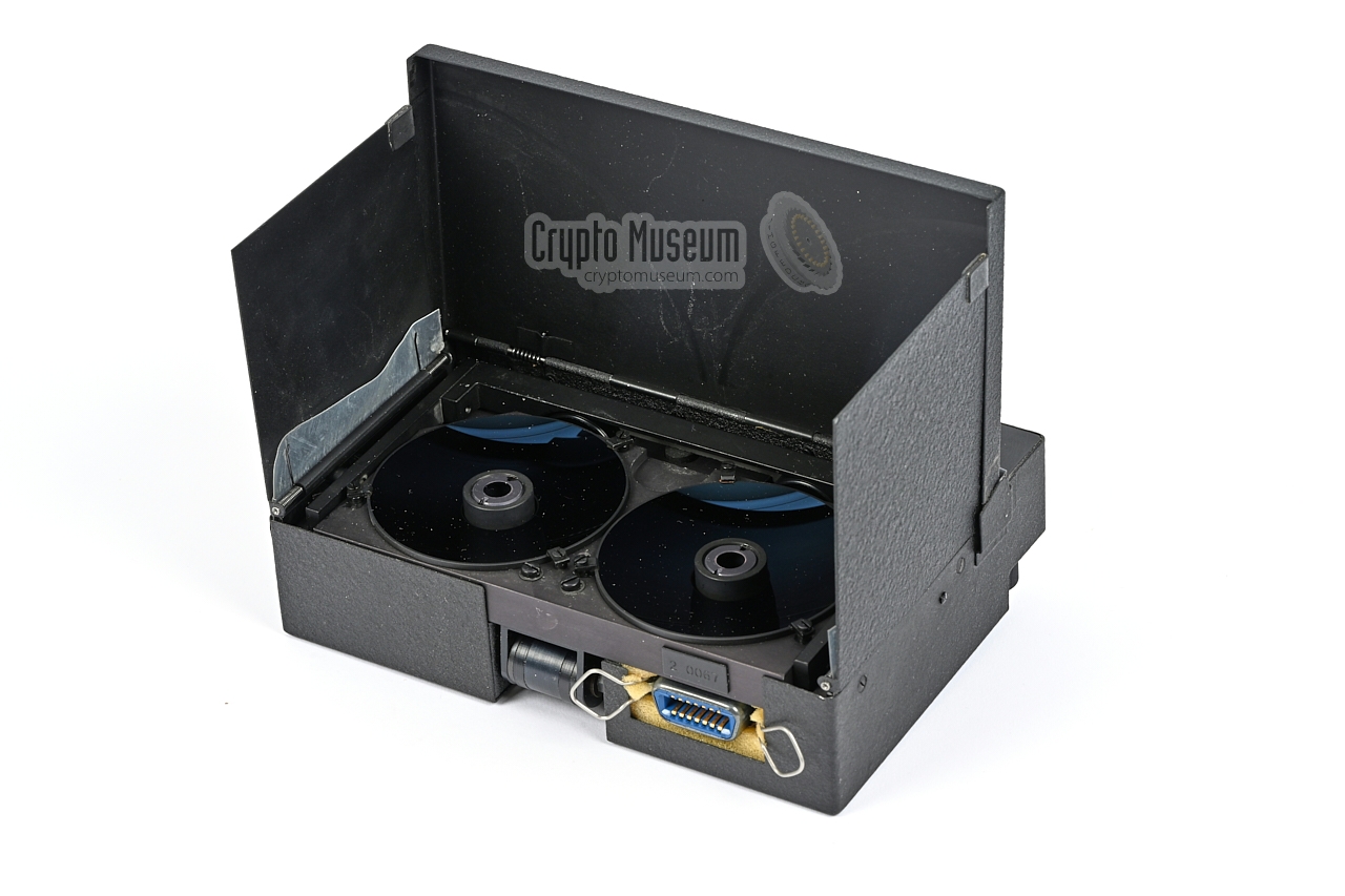
- Mirror version
This is the basic version of the JO-4.02, in which two double-mirror systems
are used: one for the receiver and one for the transmitter. The device
shown above is of this type.
The three flaps (left, right and top) have to be opened
and the mirror bar has to be raised.
This version produces a narrow parallel beam of IR light with a very small
opening angle.
- Lens version
In this version, the two double-mirror systems are replaced by two small
lenses that protrude two holes in the front surface of the device. This
version is shown below. The beam of this version is wider,
as a result of which it has a shorter operational range.
It is also known as the wide-angle version (German: Weitwinkel-Dahme) [C].
|
|
The basic version of the JO-4 uses two double-mirror systems: one for the
receiver and one for the transmitter. Each double-mirror system consists of
a large mirror – mounted in a fixed position on the
unit – and a small mirror
which is mounted on a boom that can be folded down.
|
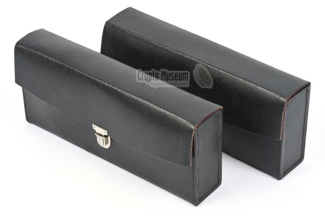
The closed device measures just 165 x 115 x 45 mm and weighs 1160 grams.
At the bottom is an adjustable hinged mount that can be fitted to a
tripod. At the front is a large spring-loaded hinged lid,
that can be opened to get access to the mirrors. After opening it,
the two spring-loaded side panels will unfold themselves.
The image on the right shows the transceiver as seen from the bottom,
with its tripod mount extended. The front lid and the side panels are
expanded (i.e. open), and form an effective 'light tunnel' to shield
the device from direct sunlight.
|
|
|
This is necessary, as sunlight rays consist of multiple wavelengths,
including infrared light, that could interfere with the modulated
infrared beam from the transceivers. After opening the lid, the
secondary mirrors have to be brought in position over the primary
mirrors, by raising the metal bar that is normally collapsed.
In the image above, it is shown in the raised (operational) position.
The diagram above shows how the patented double-mirror system works [4].
The mirrors consist of a glass body that acts as an infra-red bandpass
filter and as a lens. The reflective layer is at the rear of the glass body.
The primary mirror is a fixed part of the transceiver, whilst the secondary
mirror is mounted on a movable bar that can be lowered when the device
is stowed. At the centre of the primary mirror is the infrared light
source (TX), or the infrared detector (RX).
|
|
|
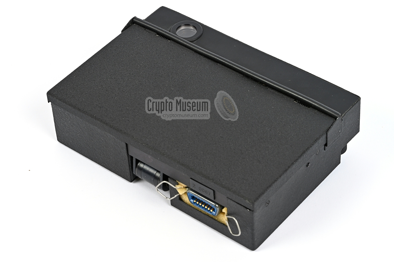
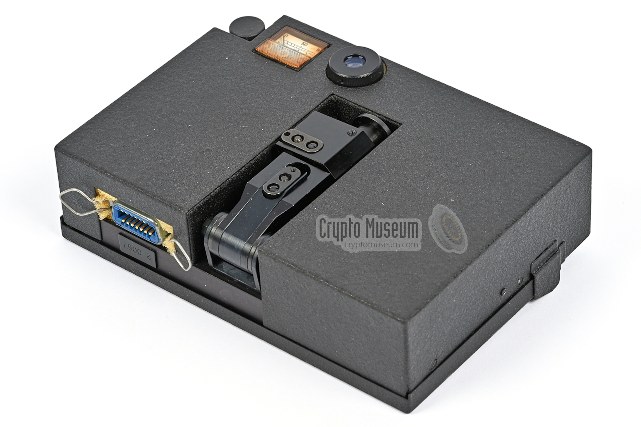
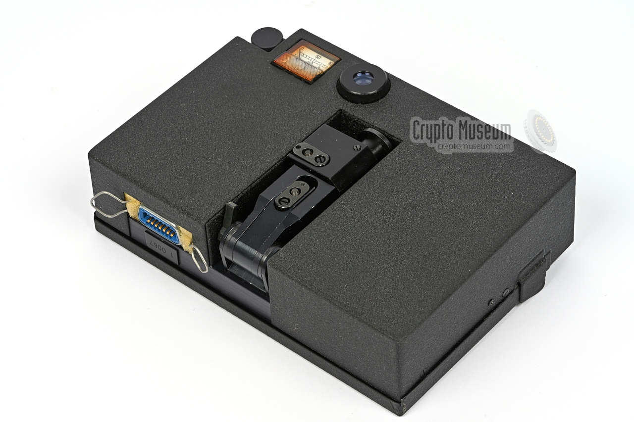
Lens version
Weitwinkel-Dahme
|
|
|
|
For situations in which the remote station – operated by an agent in a hostile area – could not be placed on a tripod and could not be
aimed accurately, the Stasi developed a modified version of the basic JO-4,
in which the two double-mirror systems were replaced by two miniature lenses.
|
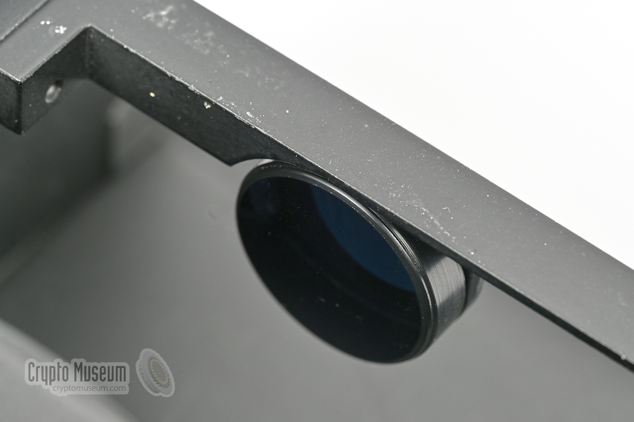
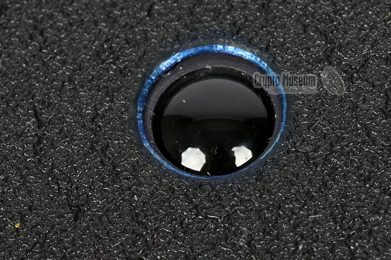
On this version, the large hinged lid at the front has
two holes through which the
transmit and receive lenses are directly visible.
The device does not have to be opened for operation.
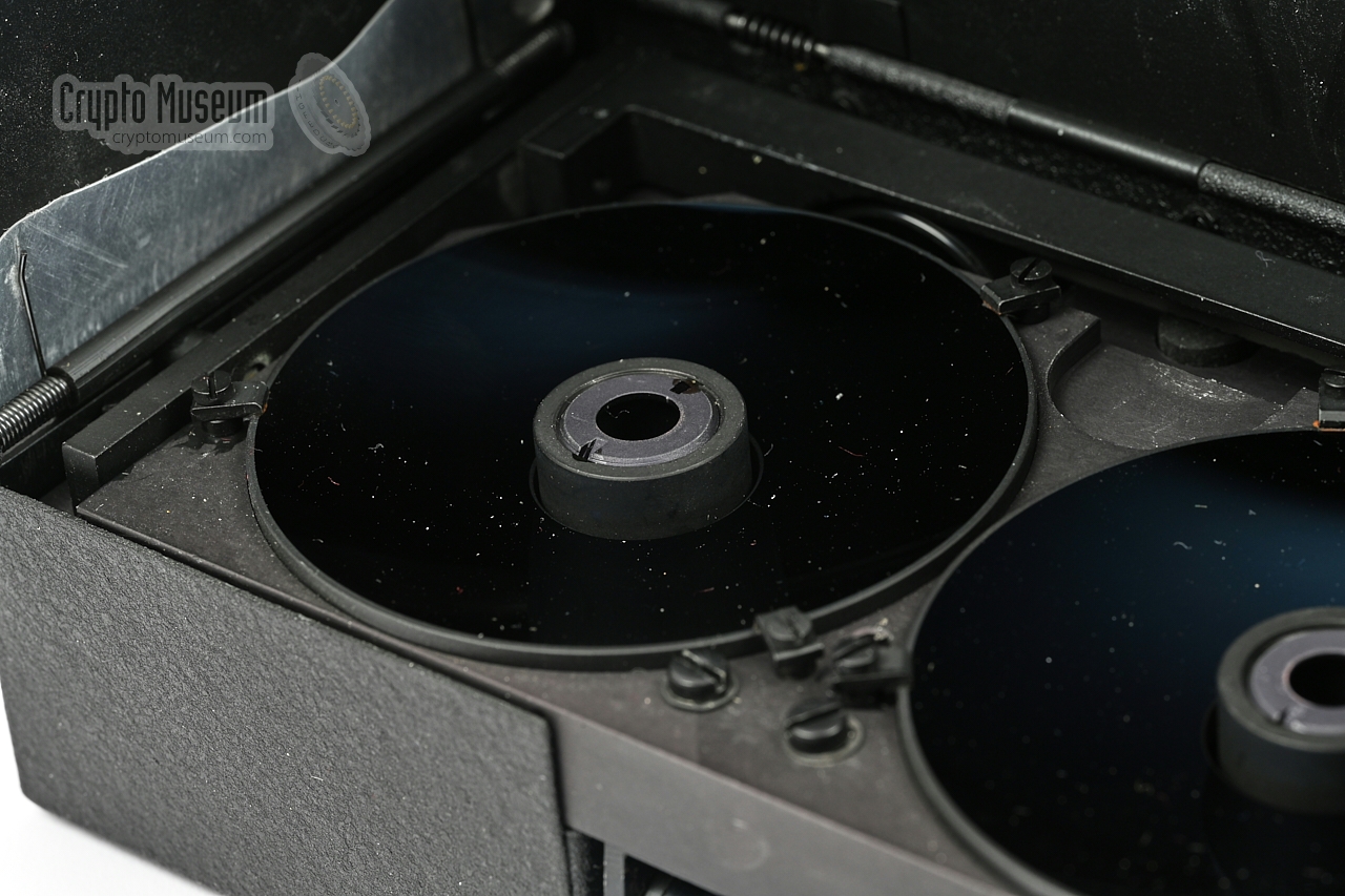
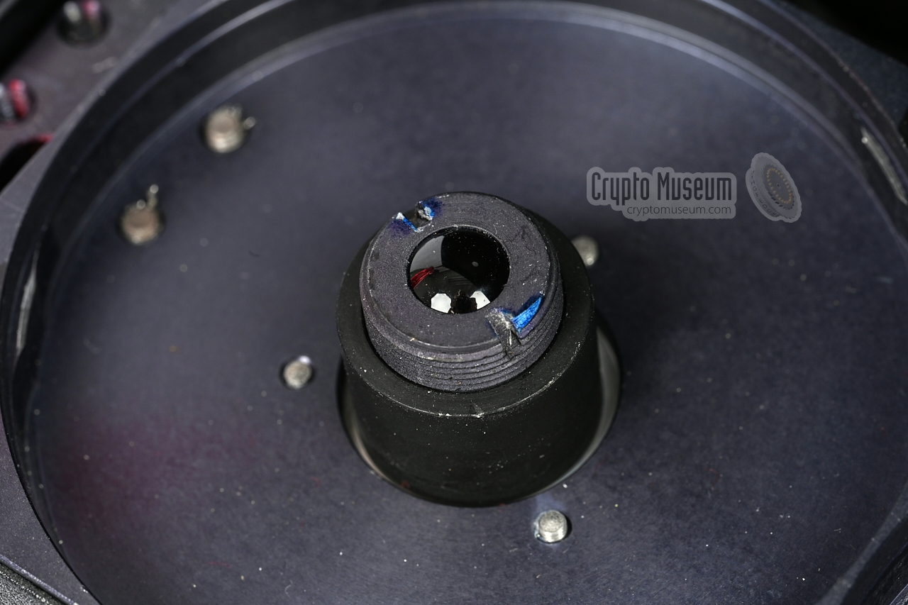
The two smaller flaps at the sides are missing. The image on the right shows
this version with the lid open. The two bays for the large mirrors are
clearly visible, but the mirrors themselves are missing. The retractable bar
with the two smaller mirrors is also missing. The two infrared
lenses are visible at
the centre of each bay.
They protrude the two holes in the hinged front lid.
|
|
|
Due to the fact that lenses are used rather than parabolic mirrors,
the IR light beam is no longer a parallel beam,
as a result of which it can only be
used when the distance between the remote station (agent) and the local
system (base) is not too large. The advantage however, is that it will still
work when the device is not aimed perfectly. This can be useful in situations
where the agent has limited time to deploy and clear the setup.
In addition, the lack of infrared filtering – caused by the absence of the
mirrors – had to be compensated by embedding IR-filters in the lenses.
The lens-version seems to be experimental, and it is currently not known in
what situations it was used and whether or not it was widely deployed.
The Weitwinkel-Dahme is described in hand-written notes [C]
that were found in the Stasi archives (BStU) [2] by Detlev Vreisleben[1].
|
|
In November 1984, the West-German authorities arrested MfS-Agent 'J'
and confiscated the JO-4 device that he had in his possession.
His setup is shown in the image below.
The device was powered by a flashlight
and was shown in the German weekly magazine Bunte in August 1985.
|
The article in Bunte caused the alarm bells to go off at
Stasi headquarters. Apparently, the JO-4 had been developed at Zeiss
at a time when secrecy and confidentiality was not yet an issue.
Consequently, many people within Zeiss were aware of the device
and its purpose.
It prompted Oberstleutnant Schulze – head of Department 31 of the
OTS – to
brief the Regional Administration for State Security
on this delicate matter [3].
In the letter,
Schulze confirms unambiguously that the device shown in the
article is a JO-4, and that the new JO-4.03 is under development.
|
|
|
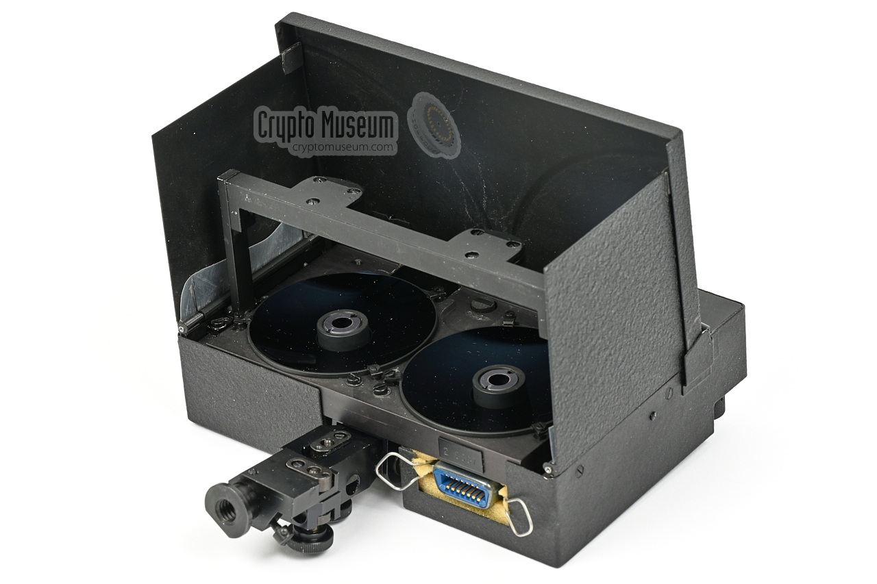
The transceiver is the heart of the system. When closed, it measures
just 165 x 115 x 45 mm and weighs 1160 grams. When the flaps are opened,
it measures 165 x 115 x 135 mm. After opening, the secondary mirrors must be
brought in position by raising the bar (as shown here).
At the bottom is an adjustable tripod mount.
Also at the bottom is a 14-pin Amphenol socket
to which the control unit must be connected.
|
|
|
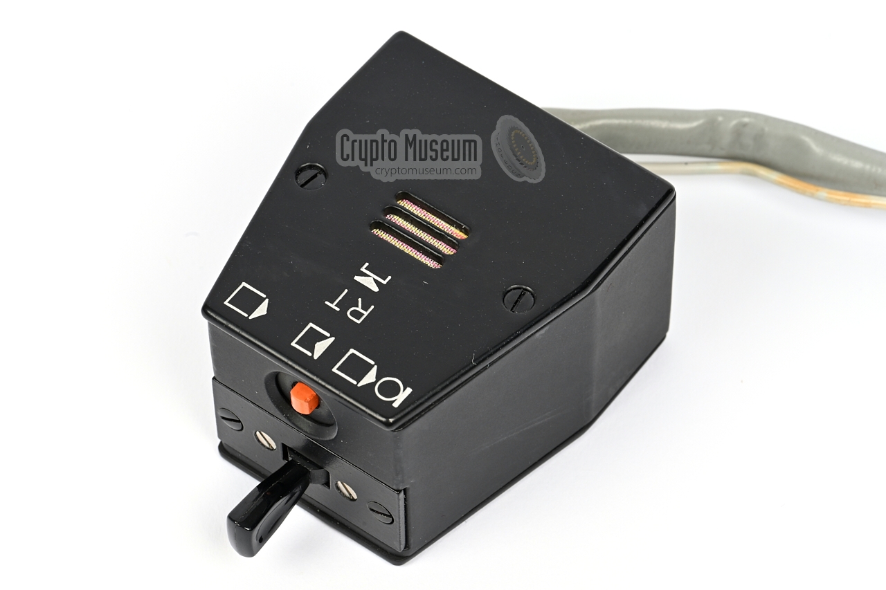
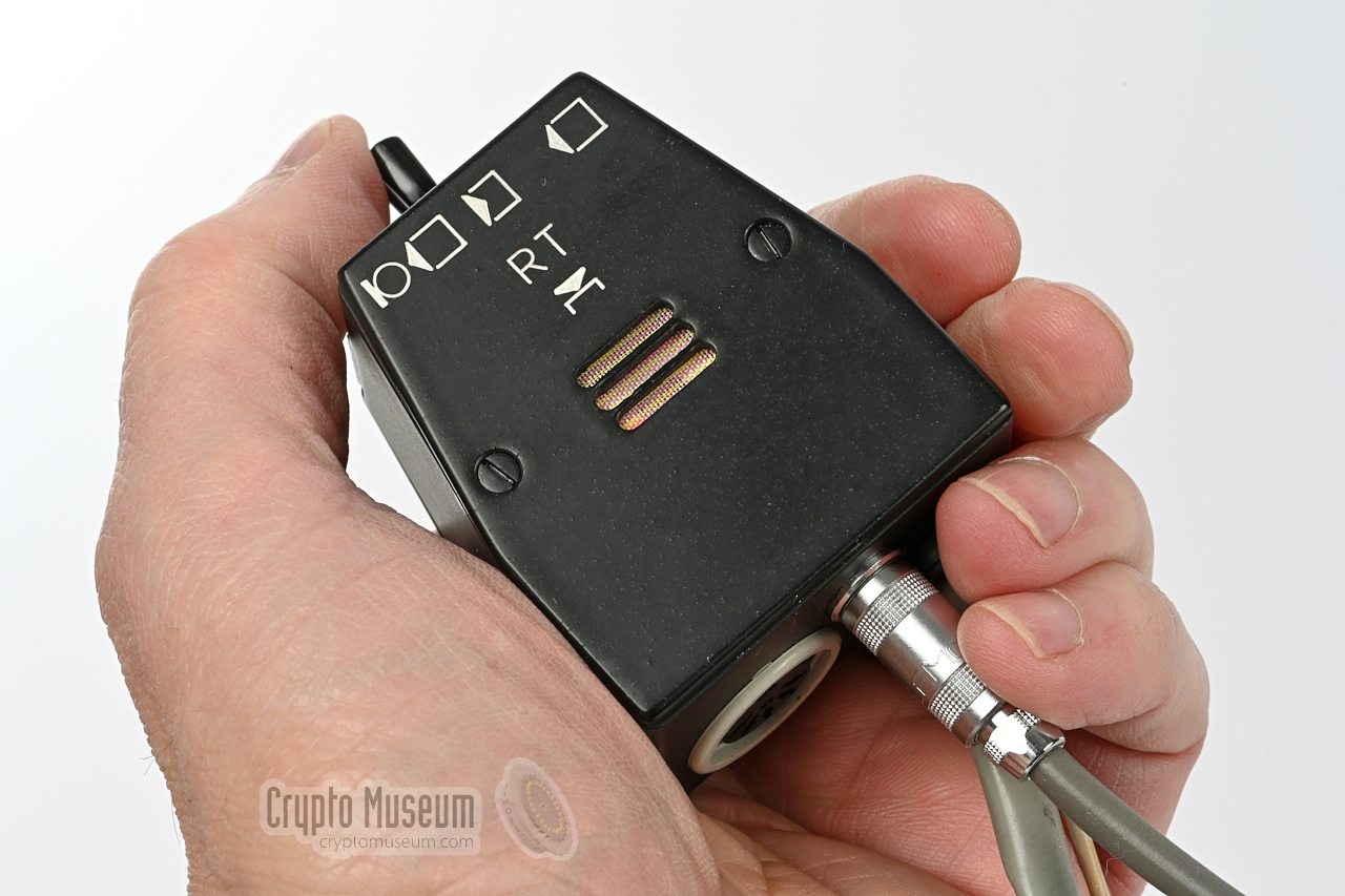
The device is operated with an external remote control unit, or handset,
that must be connected to the
14-pin Amphenol socket at the bottom.
The handset contains a microphone and has a fixed wired
earpiece.
At the top is the MODE-selector.
In the middle position (rest) the receiver is enabled.
Pushing the lever to the left enables the transmitter and the receiver
(duplex). At the top is a red button.
When pushed, the device transmits a tone to 'wake' the other party.
|
|
|
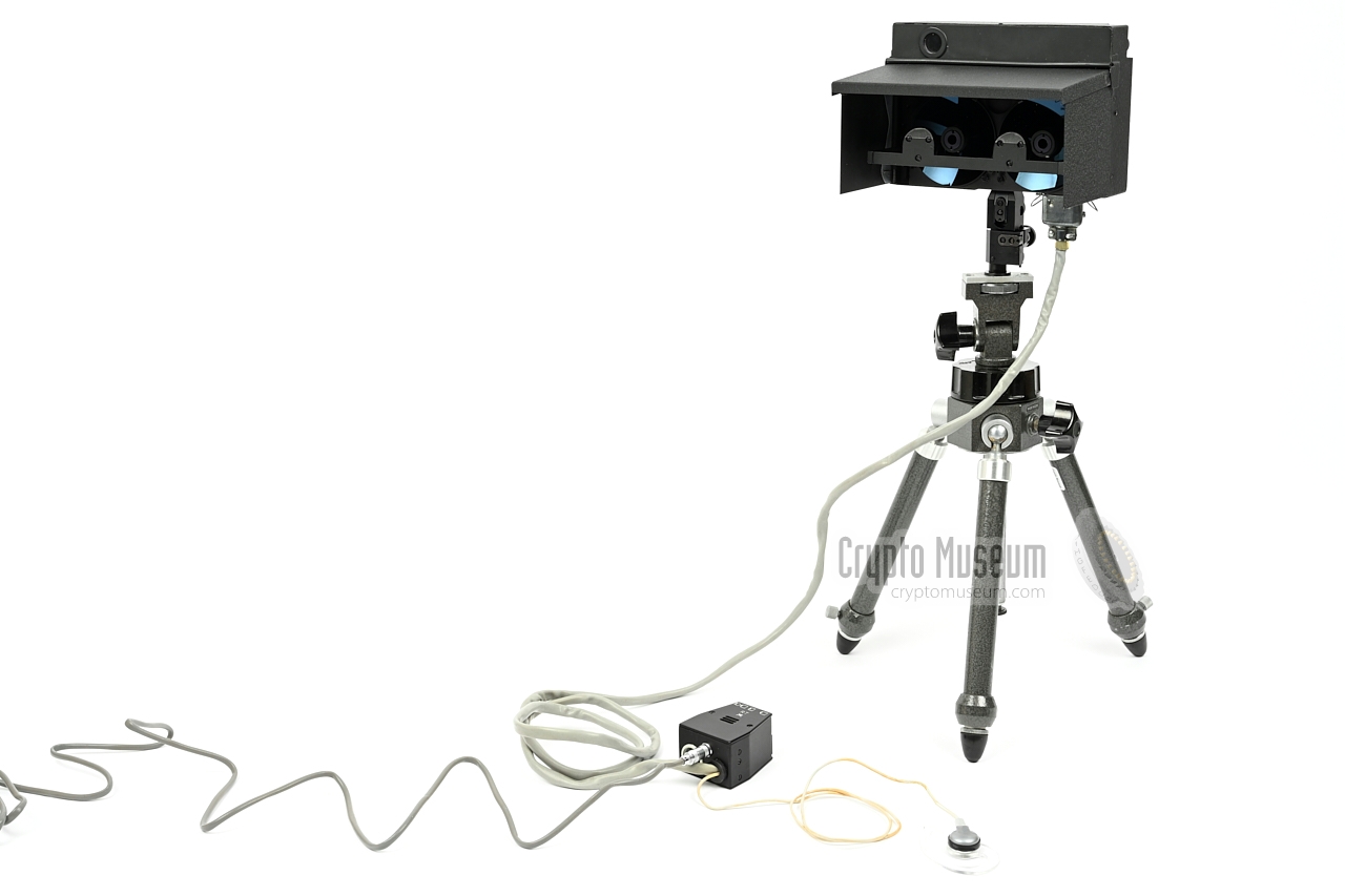
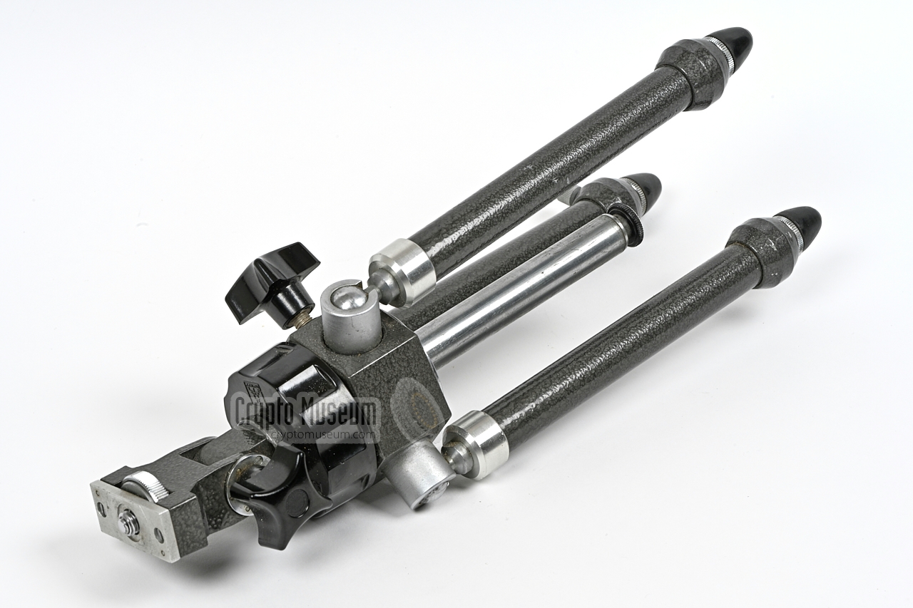
The JO-4 has an opening angle (2ω) of just 0.38°, which means that
both devices must be aligned accurately to achieve a proper and reliable
communication path. At a distance of 2 km, it illuminates just a 13 metre area.
For a proper and stable link, it is therefore mandatory to mount each
device on a tripod, such as the one shown in the image on the right.
|
|
|
The JO-4 has no provisions for fitting internal batteries.
Instead, it must be powered by means of the special power cable shown in the
image on the right. The cable has a coaxial LEMO-connector at one end – that
must be fitted to the socket at the bottom of the handset – and
an E10 lamp thread at the other end.
The E10 thread can be fitted to the E10 socket of a portable
flashlight –
it replaces the lightbulb – such as the one shown below.
Alternatively, an external power cable could be used.
|
|
|
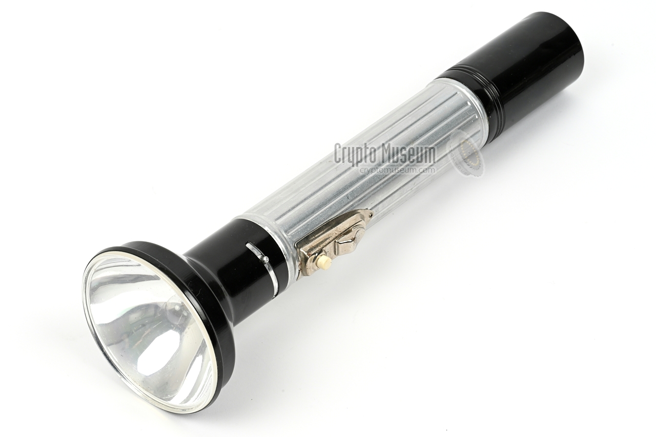
The JO-4 is powered by an external 4.5V DC source, that must be connected
to the LEMO-socket at the bottom of the handset. In most cases, an
existing portable flashlight was used for this, such as the
Narva Artas 9480 shown in the
image on the right. It uses three 1.5V D-type batteries (mono cells) which are
sufficient for many hours of uninterrupted operation.
The reflector must be removed
from the flashlight and the light bulb has to
be taken out of its E10 socket. Next, one end of the power cable
is screwed into the E10 socket.
|
|
|
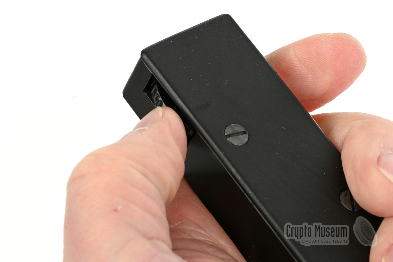
Each unit came with an adjustable attenuator that could be
connected between the handset and a tape recorder. It allows
the level of the input signal – which varies with the distance
to the opposite station – to be adjusted manually.
The device consists of a rectangular metal enclosure with a
recessed thumb-operated potentiometer. It has two fixed wires:
one that terminates in a 5-pin DIN plug, and one with a 3-pin
DIN-plug at the end.
|
|
|
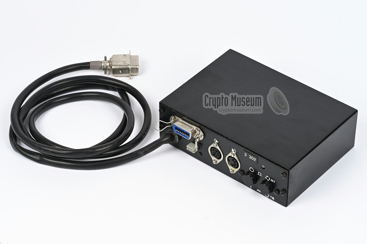
Although both devices can be used stand-alone (transceiver + handset),
one device was usually connected to the expansion unit shown in the
image on the right. It can be connected to the
power supply unit (4) (see below)
and has sockets for connection of an external recorder.
This device is missing from the JO-4 kit in our collection,
but is similar to the one supplied with the later JO-4.03.
➤ Check out the JO-4.03
|
|
|
The device could be powered from the AC mains by means of the supplied
power supply unit (PSU) shown in the image on the right. It is designated
device number 4 and is suitable for the 200-250V AC mains only.
This device is missing from the JO-4 kit in our collection,
but is similar to the one supplied with the later JO-4.03.
➤ Check out the JO-4.03
|
|
|
|
The device is powered by an external 3.5 to 4.5V DC source,
that must be connected to the LEMO-socket at the bottom of the
handset. This coaxial connector has the (+) terminal
connected to the contact at the centre.
|
|
At the bottom of the handset is a 5-pin 180° DIN socket
to which external audio devices, such as a tape recorder, can
be connected. Below is the pinout when looking into the socket.
|
- Line in (from tape recorder)
- Ground
- Line out (to tape recorder)
- Microphone in (2kΩ)
- Earphone out
|
|
Device Line-of-sight (LOS) light-based communication device (Lichtsprechgerät) Purpose Covert cross-border agent communication User MfS (Stasi) Manufacturer Carl Zeiss Jena Frequency 317 THz (940 nm) - infrared Modulation AM Operation Full duplex Bandwidth 400 - 3000 Hz (narrowband)
250 - 16000 Hz (wideband) Angle (2ω) 0.38° (transmitter)
0.28° (receiver) Power 3.5 - 4.5V DC Batteries 3 x 1.5 D-size (external) Viewfinder Γ = 5.5x, viewingle angle (2ω) = 8° Range 3 km (2 km when using wideband option) Call tone 1050 Hz ±100 Hz Pilot tone 16 kHz (crystal) Dimensions 165 x 115 x 45 mm (collapsed) Weight 1160 g
|
- JO-4
- 17305
- Neue Dahme
- Lichtsprechgerät
|
1 0067 1 2 0067 Crypto Museum (Netherlands)
|
-
This is the rare wide-angle variant (Weitwinkel-Dahme).
|
-
Document obtained from BStU [2] and kindly supplied
by Detlev Vreisleben [1].
|
-
Full name: Bundesbeauftragte für die Unterlagen des Staatssicherheitsdienstes
der ehemaligen Deutschen Demokratischen Republik
(DDR) —
Federal Commissioner for the Records of the
State Security Service
of the former German Democratic Republic (GDR) —
officially abbreviated to BStU.
-
Document obtained from BStU [2] and kindly supplied
by Detlev Vreisleben [1].
|
|
|
|
Any links shown in red are currently unavailable.
If you like the information on this website, why not make a donation?
© Crypto Museum. Created: Sunday 21 November 2021. Last changed: Wednesday, 05 November 2025 - 11:43 CET.
|
|

|
|
|