|
|
|
|
|

|
|
Opto Voice ZEISS Stasi JO-4.03 → ← JO-4.01
The device has an oval-shaped enclosure that measures 315 x 240 x 120 mm
and weighs 4346 grams, batteries not included.
Most of the space is taken by the two large double-mirrors; one for the
transmitter and one for the receiver.
If two identical units are used, communication over a distance of 5 km 2
should be feasible. In practice however, the JO-4.02 was often used as a
base station, with a smaller portable unit, such as the JO-4,
JO-4.03 or FINOW, at the other end.
Stasi (MfS) agents used the devices to exchange messages without
physically crossing the border.
|
|
|
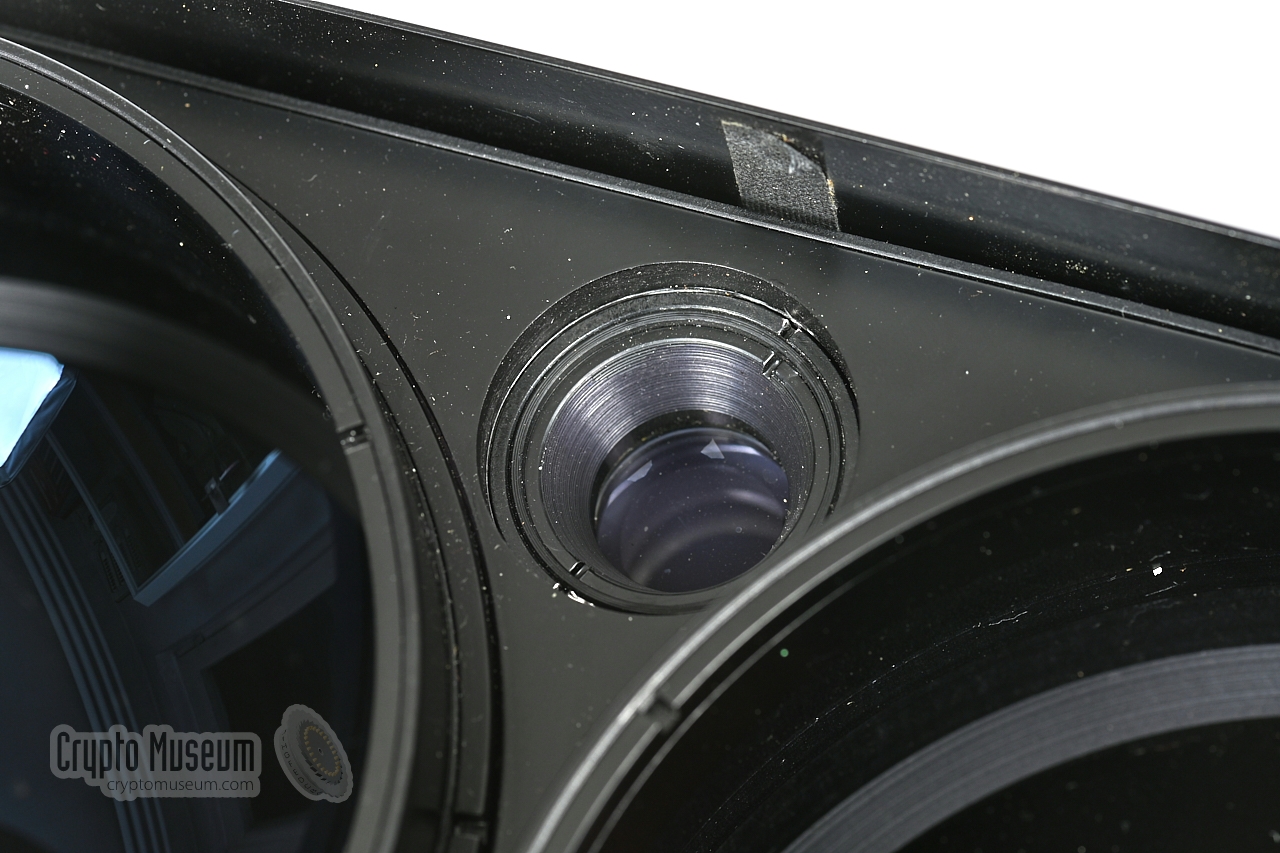
The device has a opening angle of just 0.18°.
At a distance of 1 km this is equivalent to 3 metres.
For this reason, the devices at both ends of the transmission path have
to be aligned accurately, using the built-in range scope (viewfinder)
and the mechanical adjustments of the
tripod mount at the bottom.
A wideband version of the device — suitable for the reception of
black and white video signals (CCTV) transmitted by the JO-4.05
— was known as JO-4.06.
➤ Listen to the JO-4.02
|
-
The Dahme is a river that flows in the German states of Brandenburg
and Berlin. The Stasi commonly used river names for its infra-red
(IR) communication devices. As Dahme is pronounced the same as the
German word Dame (lady), the name was easily transformed into Große Dame
(big lady).
-
In practice, much larger distances are possible. In recent years,
amateur radio operators were able to cover a distance of 14 km [5]
and in one case even 24 km [7].
|
HELP PLEASE —
We are currently looking for the complete circuit diagram of the JO-4.02.
From the Stasi archives (BStU), we have obtained the circuit diagram of
the later handset and mechanical drawings of the main unit, but
unfortunately the circuit diagram of the main unit is still missing [B].
➤ Contact us
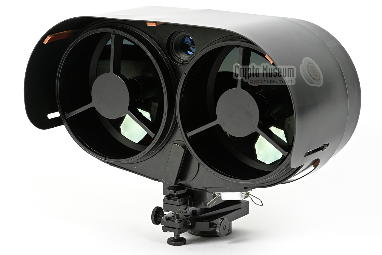
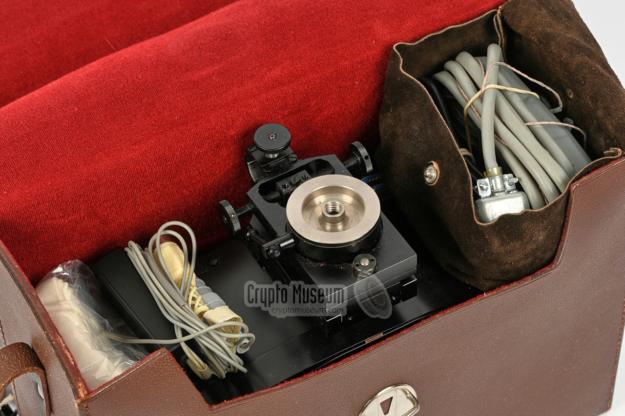
The image below provides a quick overview of features of the JO-4.02.
At the right is the device, which is here lying on its rear side.
The two double mirror systems are facing upwards, When in transit,
these mirrors are covered by aluminium caps.
At the rear is a curved overhead cap, that can be
moved forward to protect the device against
direct incoming sunlight. This is necessary, as sunlight contains
infrared rays that may interfere with the faint infrared signal
of the JO-4.02.
At the bottom of the main device is a
14-pin Amphenol socket to
which the handset must be connected. The handset has a built-in
microhone and a fixed-wired earpiece. At the bottom of the handset
is a 5-pin DIN socket
for connected of external audio equipment,
such as a tape recorder. The unit is powered by internal
batteries, or by an external 4.5V DC source (e.g. from a
portable flashlight) that is connected at the bottom
of the handset, using the supplied E10 cable.
The diagram above shows how the patented double-mirror system works [9].
The mirrors consist of a glass body that acts as an infra-red bandpass
filter and as a lens. The reflective layer is at the rear of the glass body.
The primary mirror is an embedded part of the transceiver, whilst the
secondary mirror is mounted on a fixed frame that is located over
the primary mirror. At the centre of the primary mirror is the infrared
light source (TX), or the infrared detector (RX).
|
- Transmit & receive (microphone & tape player)
- Receive only
- Transmit & receive (tape player only)
|
|
The JO-4.02 was suitable for the following applications, provided that there
was a direct line-of-sight between the two stations:
|
- Duplex speech with another JO-4.02 over distances up to 5 km
- Transfer of wideband (high-speed) tape recordings over distances of at least 3 km
- Duplex speech with the portable JO-4.03 over a distance of > 3 km
- Duplex speech and data transfer with covert FINOW device > 1.5 km
- Duplex speech with JO-4 over a distance of > 3 km
- Duplex speech with JO-4.01 over a distance of 500 m
|
|
On 17 August 2014, three German Amateur Radio Operators — DL3HRT, DL2HSX and DL2AWT —
carried out several experiments with two JO-4.02 devices and one homemade
Lichtsprechgerät — the AATiS AS802 ELiSE 1 — over a distance of no less than
14 km. The test results are available (in German) here
[5]. Below are two audio clips that were recorded during the experiments [4].
|
-
AS802 ELiSE is a homemade infrared communication device that is compatible
with the Stasi's JO-4.02 and similar devices. It is available from the
German amateur radio club AATiS as
self-build kit AS802 ELiSE
[6].
|
The diagram below shows a typical setup with the JO-4.02 (Große Dahme)
as the local station (2). At the left is the remote station (1), which
can be any infrared communication device from the
JO-4.xx series.
When this is another JO-4.02, it should be possible
to cover a range of 5 km or more.
Each of the devices can have a tape recorder connected to the handset,
which can be used for recording or playback. At the JO-4.02 side, it
can be used for high-speed audio recording or playback, typically at
2x or 4x the regular speed, as it has a bandwith of 16 kHz. Some other
models also support high-speed data transfer. Check the
relevant pages for further information.
|
|
|
Advanced and high-speed setup
|
|
|
In the advanced setup, the JO-4.02 was commonly used as the base station,
with a much smaller portable device, such as the JO-4 or the
JO-4.03 at
the other end. By connecting an expansion unit and a mains power supply
unit to the JO-4.02, the base station could be converted into an unmanned
automatic-recording station. This configuration is shown in the diagram below.
|
| |
Advanced setup with external power and recording facility
|
In this setup, normal full-duplex voice transmissions are possible, just as
in the basic setup. But it is also possible to use the local system (2)
as an unmanned auto-recording station. It allows the voice transmissions from
the remote station (1) to be recorded onto an external UHER recorder.
In this configuration, the local station (2) can be used as an
electronic dead letter box (EDLB).
It allowed an agent to deliver his message without the need to establish
a two-way contact first.
Automatic recording is possible by the virtue of a 16 kHz pilot tone –
transmitted by unit (1) – that activates a recorder
that is connected to the local station (2). For this to work, unit (1)
has to be either a JO-4 (Neue Dahme), or a
JO-4.03 (Kleine Dahme) of which the serial
number starts with '1' (e.g. 1 302).
In the same vain, when configured apropriately,
the remote station (1) can also be used to collect
pre-recorded messages from the tape recorder at the local station (2).
The expansion unit and the PSU are currently missing from the JO-4.02
kit in our collection. They are very similar though, to the expansion unit
and the PSU of the JO-4.03 (Kleine Dahme). Follow the link
below for other possible configurations when used in combination
with the JO-4.03.
➤ Check out the JO-4.03
|
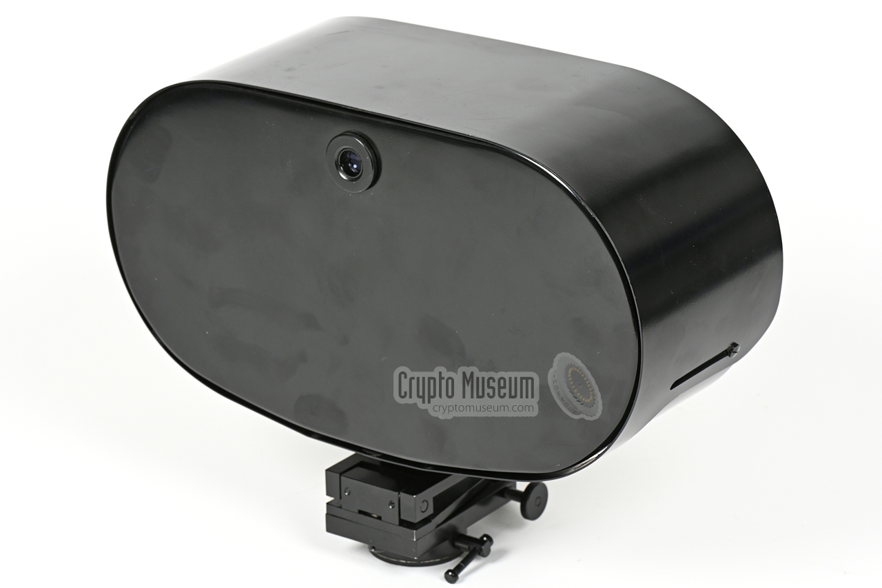
The transceiver is the heart of the system. With the sunlight cap
retracted, it measures 315 x 240 x 120 mm and weighs 4346 grams.
At the bottom is an adjustment mechanism with photographic thread,
suitable for mounting it on a regular tripod. The device
has a 14-pin Amphenol socket at the bottom, to which the
handset must be connected.
|
|
|
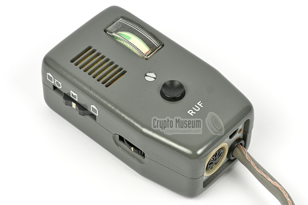
The device is operated with an external remote control unit, or handset,
that must be connected to the
14-pin Amphenol socket at the bottom.
The handset contains a microphone and has a fixed wired earpiece.
At the left is the MODE-selector and the volume control
which also acts as the ON/OFF switch.
Pushing the black button at the front, transmits a 1000 Hz tone
to 'wake' the other party. The meter in the upper right corner
shows audio level or battery power.
|
|
|
The grey metal handset shown above was later replaced with a black
plastic one, in which the analogue meter was replaced by a LED-bar.
In addition, the MODE-selector has moved from the left side
of the handset to the front, whilst the
external power socket has been replaced by a more secure SMC connector.
|
|
|
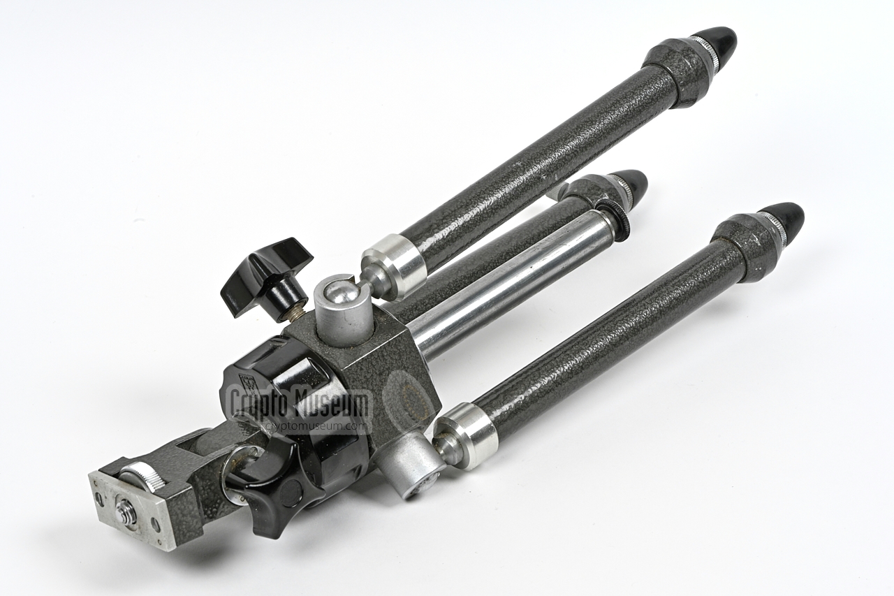
The JO-4.02 has an opening angle (2ω) of just 0.18°, which means that
both devices must be aligned accurately to achieve a proper and reliable
communication path. At a distance of 2 km, it illuminates just a 13 metre cone.
For a proper and stable link, it is therefore mandatory to mount the two
devices on a tripod, such as the one shown in the image on the right.
|
|
|
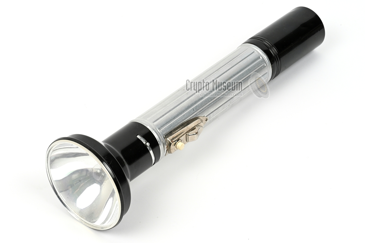
The JO-4.02 is normally powered by internal batteries, but
can also be powered externally from a regular 3-battery
flashlight, using the special power cable shown in the image on the
right. It is installed instead of the lightbulb.
In addition, cables are present
for the connection of an UHER tape recorder,
and (optionally) for the connection of an alternative power source.
|
|
|
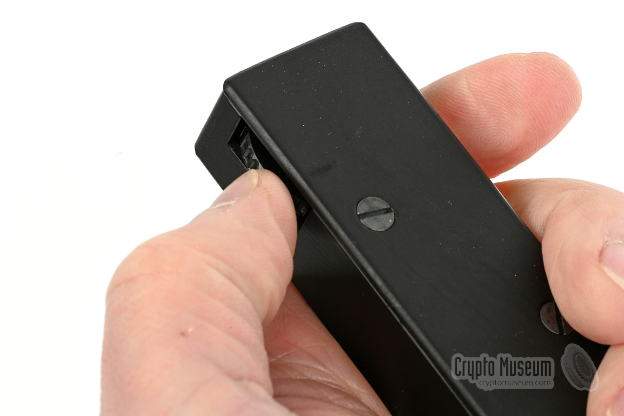
Each unit came with an adjustable attenuator that could be
connected between the handset and a tape recorder. It allows
the level of the input signal – which varies with the distance
to the opposite station – to be adjusted manually.
The device consists of a rectangular metal enclosure with a
recessed thumb-operated potentiometer. It has
two fixed wires:
one that terminates in a 5-pin DIN plug, and one with a 3-pin
DIN-plug at the end.
|
|
|
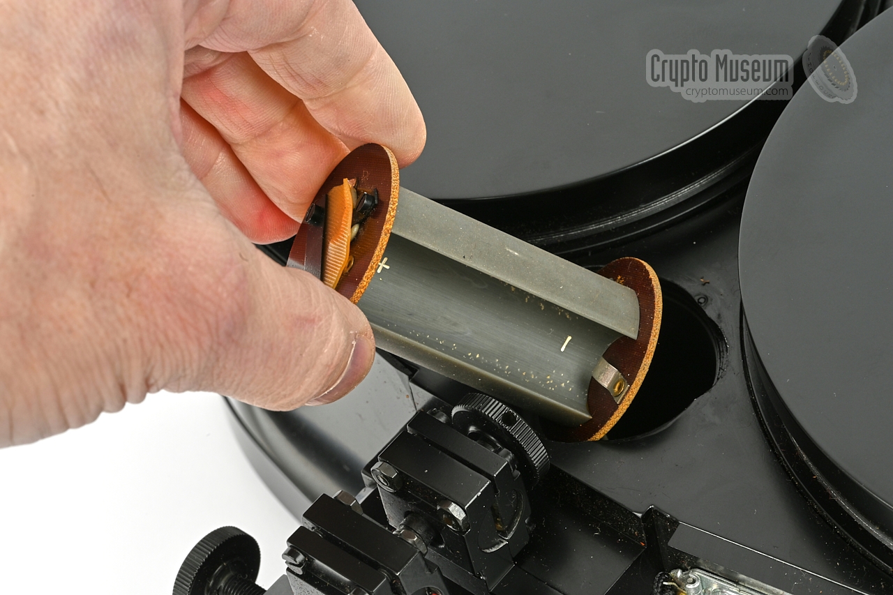
If necessary, the JO-4.02 can be powered externally by a 4.5V
DC source — typically a 3-battery flashlight
like the Narva Artas 9480 shown
in the image on the right — using the supplied E10 power cable.
The reflector must be removed
from the flashlight and the light bulb has to
be taken out of its E10 socket. Next, one end of the power cable
is screwed into the E10 socket. Move the mouse over the image to see
how this works.
|
|
|
For a good and reliable connection over a range of several kilometres,
it is important that the optical parts of the device are kept as clean as
possible and free from dust. When the device is not in use, the black
aluminium caps should be placed over the mirrors.
To remove any dust or dirt from the mirrors, a piece of lint-free cloth
and a small brush was supplied with every kit.
|
|
|
|
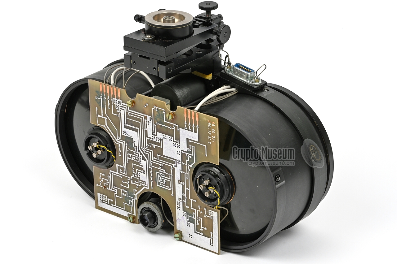
The interior of the JO-4.02 is easily accessible. First, the light shielding
cap has to be removed. It is held in place with two screws; one on each side.
Next, the viewfinder adjustment ring has to be removed (one miniature screw),
followed by four screws around the edges of the outer case shell.
|
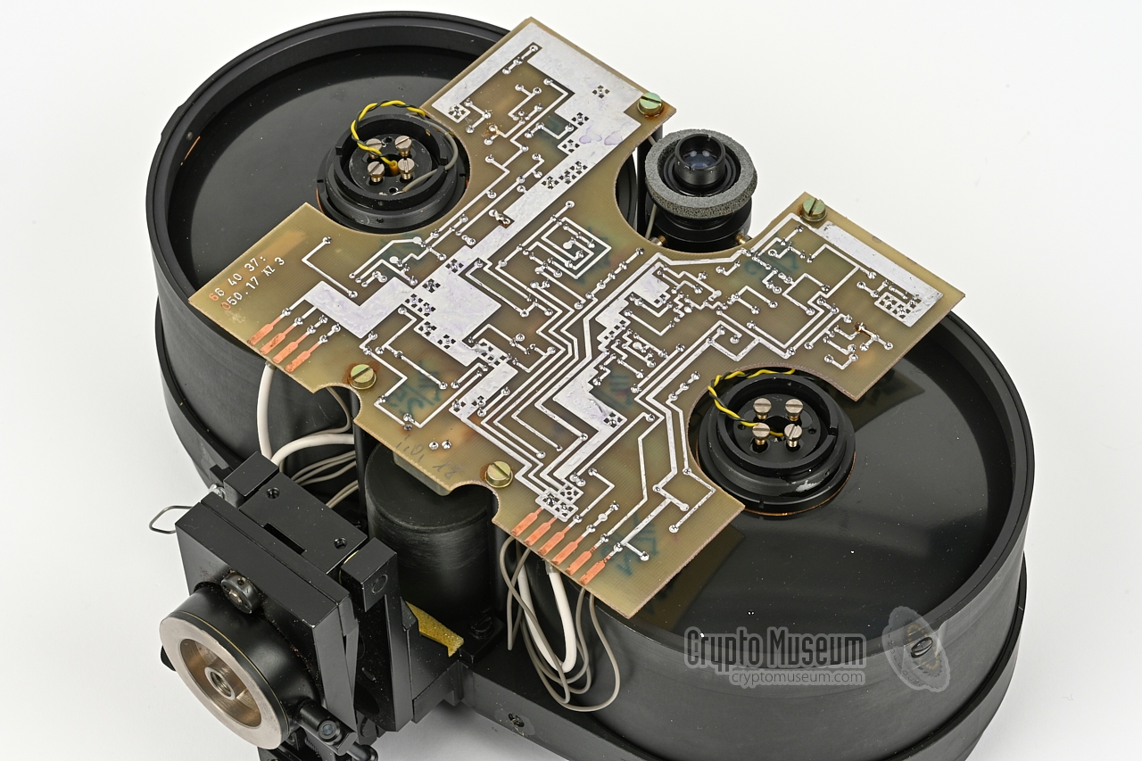
The case shell can now be removed by pulling it towards the rear of the device.
This reveals the interior as shown in the image above. At the centre is the
printed circuit board (PCB) of which the solder side is visible. The PCB has
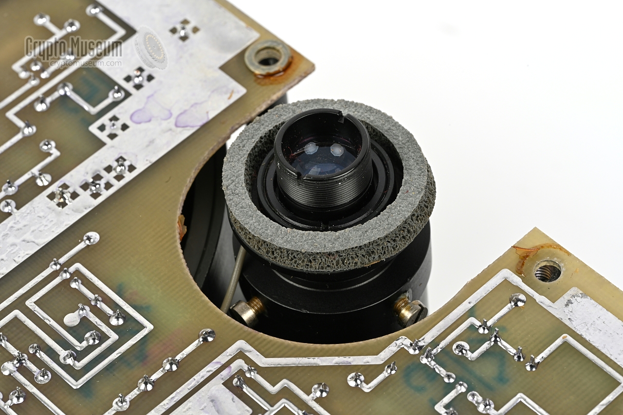
three large curved cut-outs: one for the viewfinder, one for the
VQ120 IR-LED of
the transmitter, and one for the SP211
IR photo-transistor of the receiver.
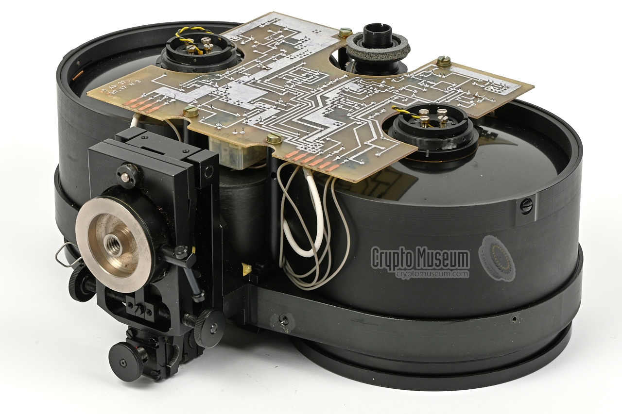
The PCB isheld in place with four screws. After removing these screws
the PCB can be tilted outwards, as shown in the image on the right, but
be careful not to damage the delicate wiring.
|
|
|
|
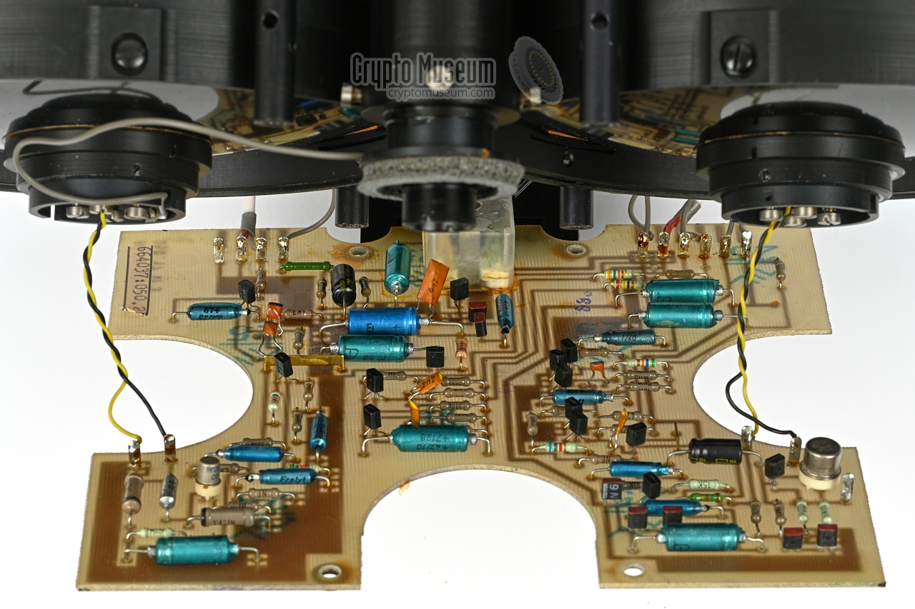
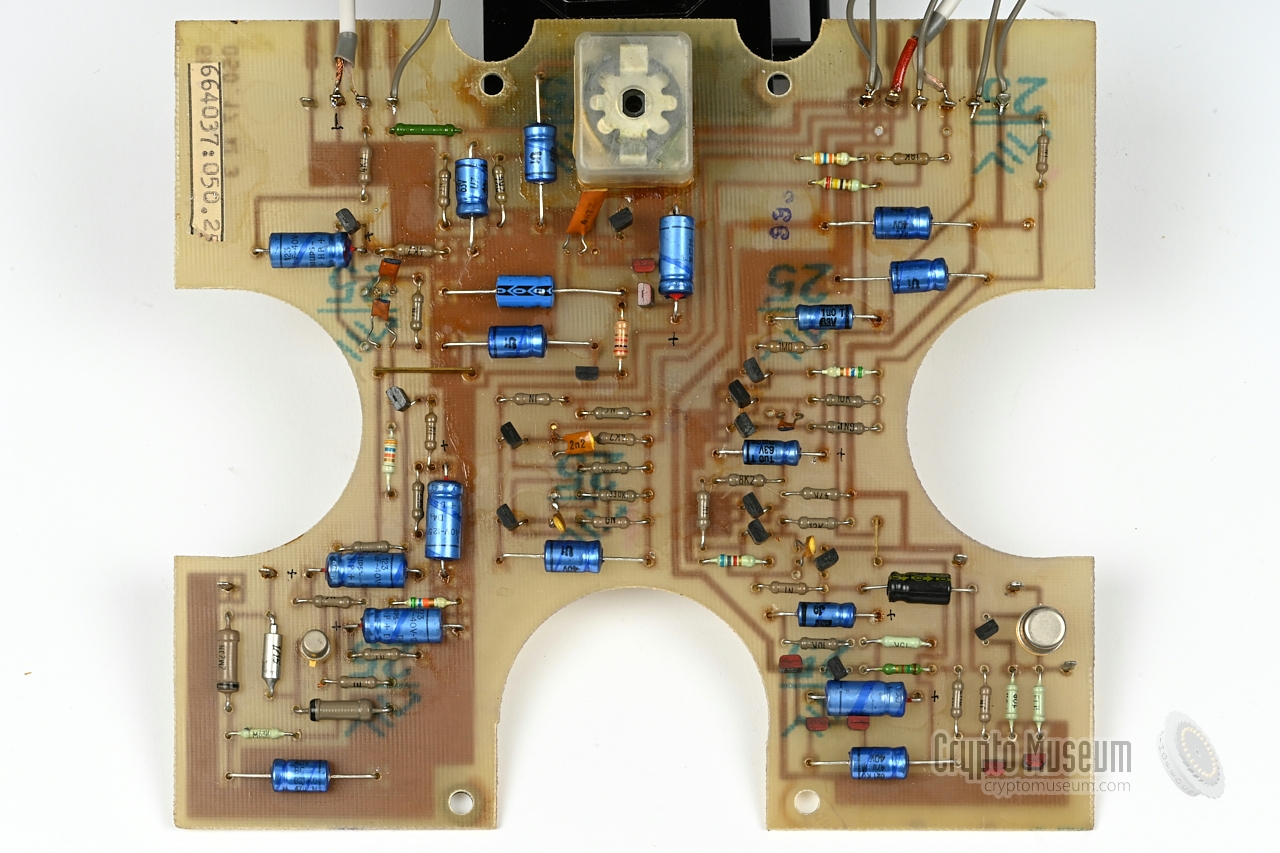
Compared to the handset [B], the circuit of the main device is
relatively simple. At the left is the receiver, whilst the transmitter
circuit is at the right. At the far end of the board is the wiring to
the 14-pin Amphenol connector. The two flying wires go to the IR LED
and IR photo-transistor.
|
As the electrolytic capacitors had almost certainly degraded after all
these years, we decided to replace all of them. To make this a bit easier,
we temporarily desoldered the yellow and black wires to the IR LED and the
IR photo-transistor. This allows the PCB to be placed horizontally.
Once all electrolytic capacitors were replaced,
the wiring was restored and the PCB was mounted back in place.
Finally the case shell was put on
again and the device was ready for use. Testing it against a known good
JO-4 unit revealed that the audio quality had improved considerably
as a result of the restoration.
Checking the removed capacitors with an LCR-meter, confirmed that
their capacity had approximately halved, whilst the ESR
had more than doubled.
|
Device Line-of-sight (LOS) light-based communication device (Lichtsprechgerät) Purpose Covert cross-border agent communication Model JO-4.02 Name Große Dahme Designator 17304 Manufacturer Carl Zeiss Jena Year 1986 User MfS (Stasi) Frequency 317 THz (940 nm) - infrared Modulation AM Operation Full duplex Angle (2ω) 0.18° (transmitter) IR output 1 mW Range 5 km (duplex speech)
3 km (wideband tape)
1.5 km (against FINOW)
500 m (against JO-4.01) Power 3.5-4.5V DC Battery 3 x R6 1.5V External From 3 x R20 in flashlight Current 35 mA (receive)
150 mA (transmit) Bandwidth 250 Hz - 3200 Hz (earpiece)
250 Hz - 6000 Hz (microphone)
250 Hz - 16 kHz (tape recorder) Input 0.25 mW into 2 kΩ Output 0.7V into 10 kΩ Range scope 5.5 × enlargement, 2ω = 7° Temperature -20°C to +45°C Dimensions 315 x 240 x 120 mm Weight 4346 g (without batteries)
|
- Main unit (transmitter, receiver, range scope, tripod-mount and battery holder)
- Control unit (earpiece, microphone, control cable and power cable)
- Leather storage case with carrying strap
|
- Expansion unit for auto-recording
- Mains power supply unit
|
- JO-4.02
- 17304
- Große Dahme
- Lichtsprechgerät
|
108 Crypto Museum, Netherlands 101062 Private collector, Austria
|
|
The device is powered by an external 3.5 to 4.5V DC source,
that must be connected to the power socket at the bottom of the
handset. This coaxial connector has the (+) terminal
connected to the contact at the centre.
|
|
At the bottom of the handset is a 5-pin 180° DIN socket
to which external audio devices, such as a tape recorder, can
be connected. Below is the pinout when looking into the socket.
|
- Line in (≤ 70dB)
- Ground
- Line out (16 kHz bandwidth) (to tape recorder)
- Microphone in (2kΩ)
- Earphone out
|
|
-
Document obtained from BStU [2] and kindly supplied
by Detlev Vreisleben [1].
|
- Detlev Vreisleben, Personal correspondence
November 2021.
- Bundesbeauftragte für die Stasi-Unterlagen (BStU) 1
Federal Commissioner for the Stasi-Records.
- Ob.Lt. Schultze, Information zum Produktionsthema JO 4
MfS, 21 October 1985. 2
- Karsten Hansky, Personal correspondence
December 2021.
- Karsten Hansky et al., Lichsprechversuche am 17. August 2014...
Experiments with JO-4.02 and homemade device over 14 km (German).
DL3HRT, DL2HSX & DL2AWT, 17 August 2014.
- AATiS, AS802 Simple light transceiver (self-build kit)
AS802 Einfacher Licht-Sende-Empfänger (ELiSE).
Retrieved December 2021.
- Peter Greil (DL7UHU), www.lichtsprechen.de
15 January 2005. p. 4.
- Günter Hütter, Personal correspondence
September 2021.
- German Patent DD265972, Mangin-Zweispiegelsysteme
Filed 5 November 1987.
|
 |
-
Full name: Bundesbeauftragte für die Unterlagen des Staatssicherheitsdienstes
der ehemaligen Deutschen Demokratischen Republik
(DDR) —
Federal Commissioner for the Records of the
State Security Service
of the former German Democratic Republic (GDR) —
officially abbreviated to BStU.
-
Document obtained from BStU [2] and kindly supplied
by Detlev Vreisleben [1].
|
|
|
|
Any links shown in red are currently unavailable.
If you like the information on this website, why not make a donation?
© Crypto Museum. Created: Sunday 21 November 2021. Last changed: Wednesday, 05 November 2025 - 11:44 CET.
|
|

|
|
|


![Complete JO-4.02 kit (newer model) [8]](img/303708/017/full.jpg)


