|
|
|
|
|

|
|
Receiver OWVL Cold War Sony
Miniature short-wave receiver
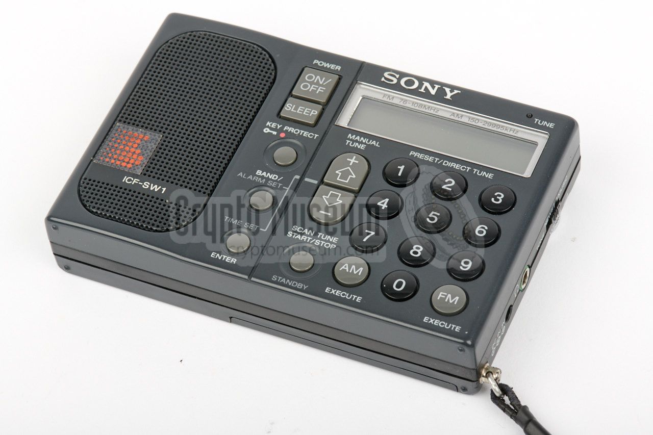
ICF-SW1 is a miniature LW, MW, SW and FM receiver,
also known as a travel receiver or a world receiver,
made around 1988 by Sony
in Tokyo (Japan). Although these receivers were intended for the
civil market, they were also used by spies and agents for the reception of
Numbers Stations.
|
The receiver measures just 11 x 7 x 2 cm, and weighs no more than
225 gr, batteries included, making it one of the
smallest in its class.
The radio is powered by two internal 1.5V AA-size dry batteries, but can
also be powered by an
external 3V DC source.
By using an (optional) cable,
it can also be powered by a car battery.
The image on the right shows a typical SW1 ready for use. It is suitable
for the reception of narrowband and wideband AM and FM signals, but not for
Single Side Band (SSB) signals, which is regarded by many as a serious
shortcoming.
|
|
|
|
Nevertheless, the radio is most suitable for travellers, for example for the
reception of the (BBC) world service on the short wave radio bands. Likewise,
the sensitive receiver was loved during the Cold War by spies and agents, who
used the short waves for the reception of coded messages, broadcast by the
mysterious Numbers Stations.
The SW1 was succeeded in 1994 by the SW100.
|
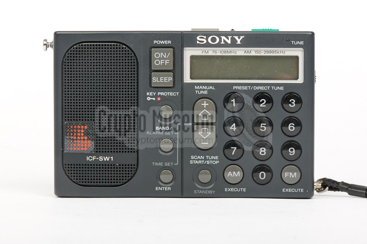
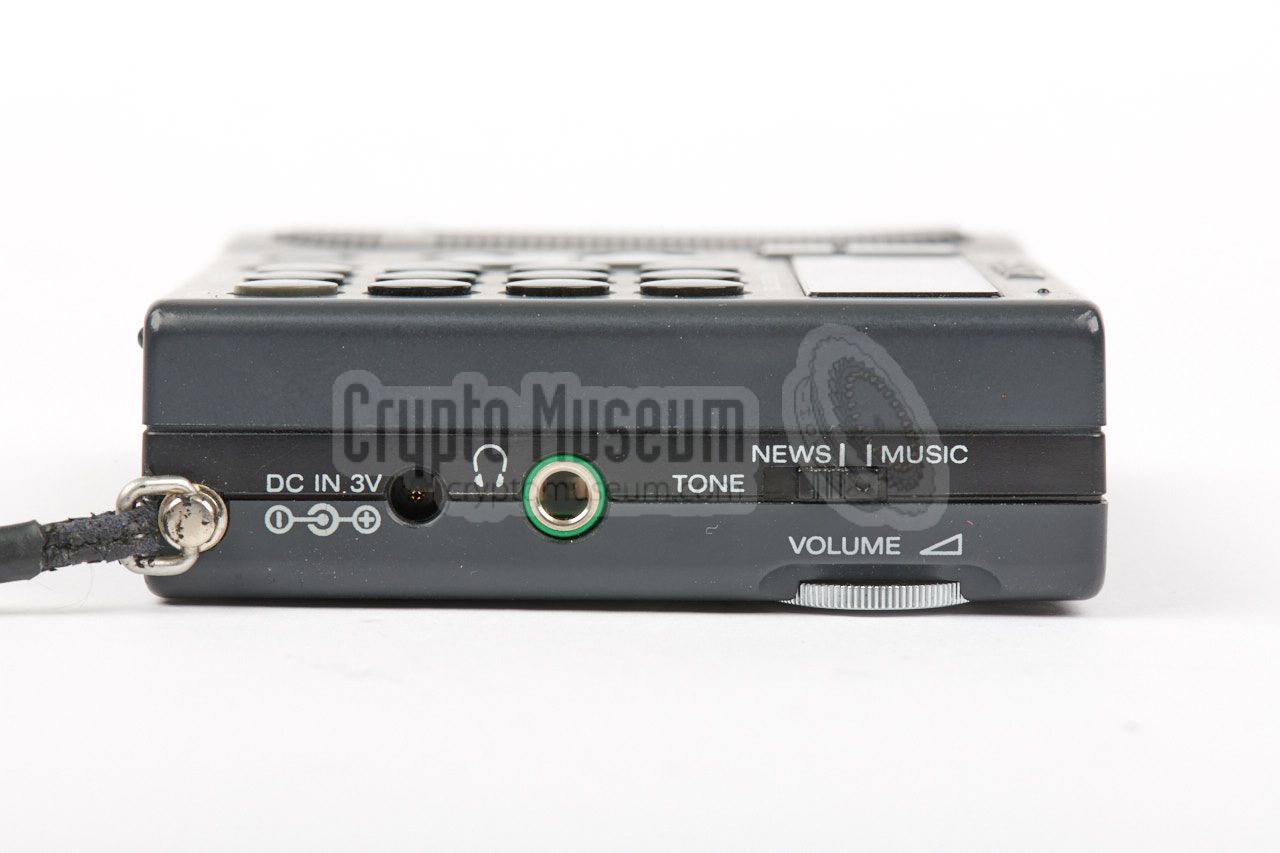
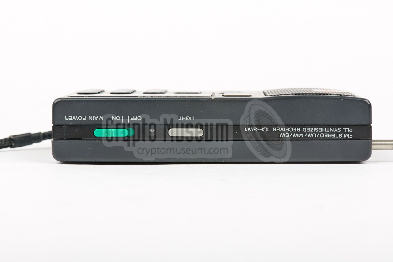
The diagram below gives a good overview of the various controls and connections
of the SW1. As the radio has controls at all sides, we are showing it here
upside down. Most of the front panel is taken by the keypad and the
liquid crystal display (LCD). At the left is a high-quality speaker.
The (green) slide switch at the top
is the main power control.
Once enabled, the ON/OFF button has to be pressed to activate the receiver.
Note that the volume control is at the rear, but can be operated from the
right. If necessary, an earphone can be connected to a 3.5 mm jack socket at
the right side.
Additionally, a (tape) recorder can be connected to a
similar socket at the left side.
|
|
Due to legal restrictions in some countries, Sony produced different
versions of the ICF-SW1. The version can be determined by examining the
text printed above the LCD display. It shows the FM and AM frequency
range supported by this version. The following versions are currently known:
|
| Type | AM | FM | Remark |
|
|
| 1 | 150 - 29,995 kHz | 76 - 108 MHz | Export version |
| 2 | 150 - 26,100 kHz | 87.5 - 108 MHz | German version |
| 3 | 150 - 29,995 kHz | 87.5 - 108 MHz | European version |
| 4 | 150 - 285 kHz + 531 - 26,100 kHz | 87.5 - 108 MHz | Saudi Arabia |
|
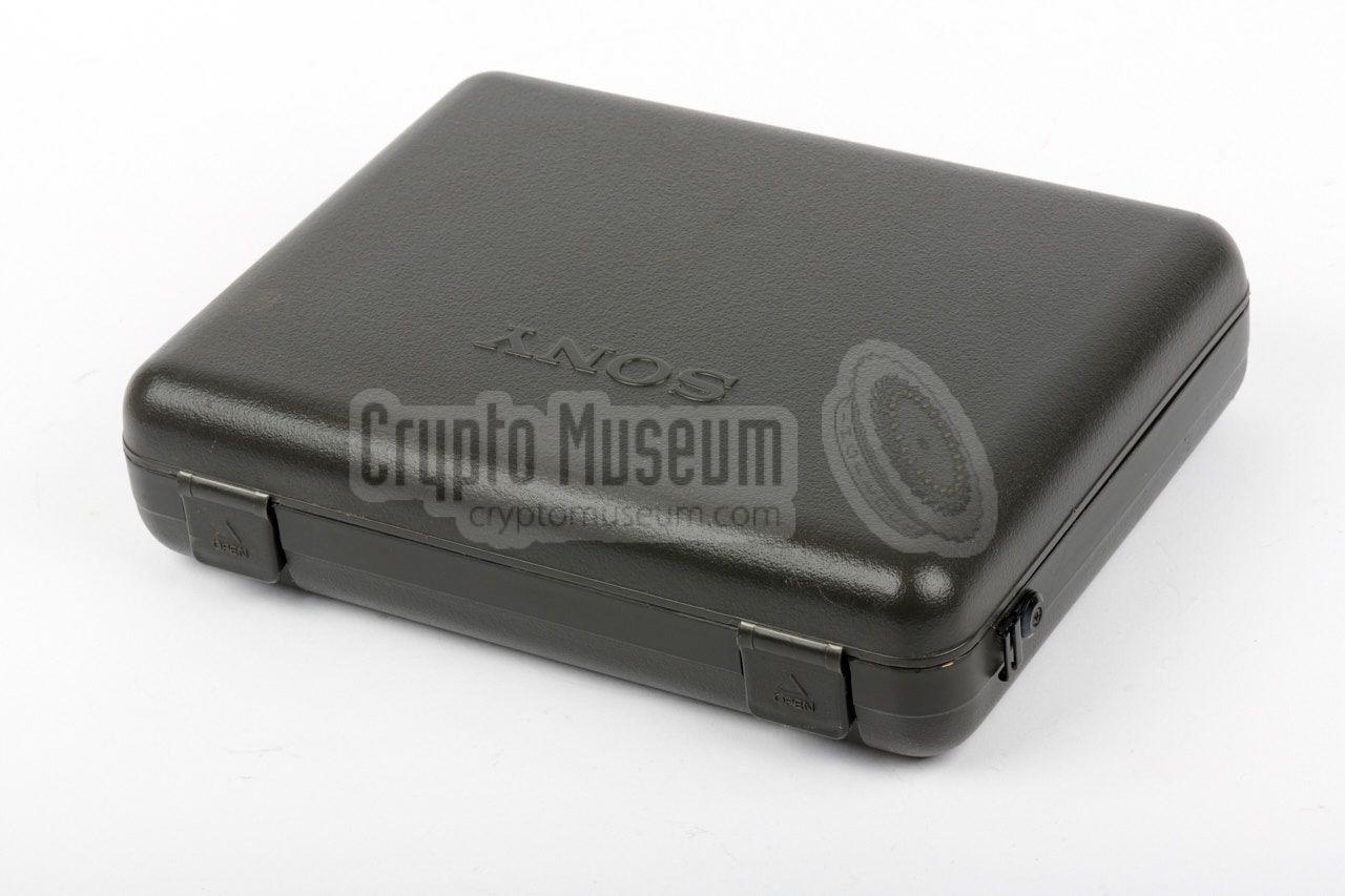
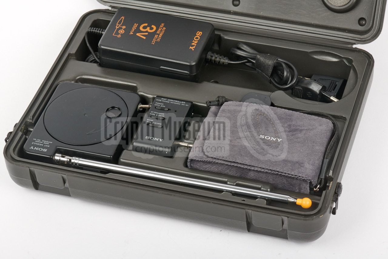
The Sony ICF-SW1 was delivered in a hard
plastic storage cassette,
of which the bottom half contained the radio and all accessories,
whilst the operator's manual was held in the top lid.
The image on the right shows the bottom half of the storage case.
At the front left is the wide range active antenna, with its
telescope antenna stowed along the front edge. At the rear is the
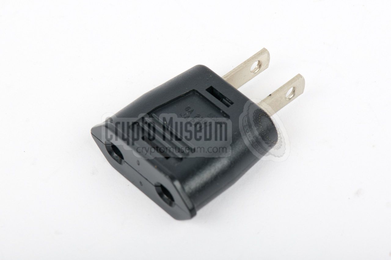
mains adapter. An adapter plug is available to allow it to be connected
to US wall sockets as well. The radio itself is at the front right.
|
|
|
To protect the radio from dirt and dust, it was usually carried in the
soft wallet shown in the image on the right. It also protected the display
against scratches.
Note that the wrist strap is attached to the radio, rather than to the
wallet. The plastic clip at the end of the wrist strap can be inserted at
the back of the radio, to allow its control panel to be tilted when placed
on a flat surface (e.g. a table top).
|
|
|
A larger carrying belt was supplied to allow the large plastic storage box
to be carried on the shoulder. It can be attacked to the metal brackets at
each side of the box.
The carrying belt is identical to the one that was supplied with the
ICF-PRO70 and ICF-PRO80.
|
|
|
The radio is powered by just 3V DC, which can be delivered either by the
internal batteries (two 1.5V AA-size penlight cells) or by the external
power supply unit (PSU) shown in the image on the right.
When using an alternative PSU, please note that – like most other Sony
products – the centre pin of the connector carries the (-) rather than
the (+) terminal.
➤ view connection
|
|
|
|
|
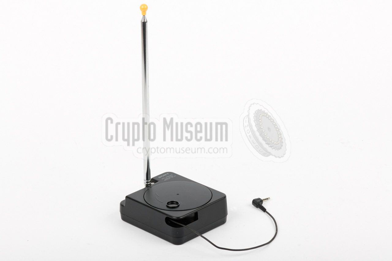
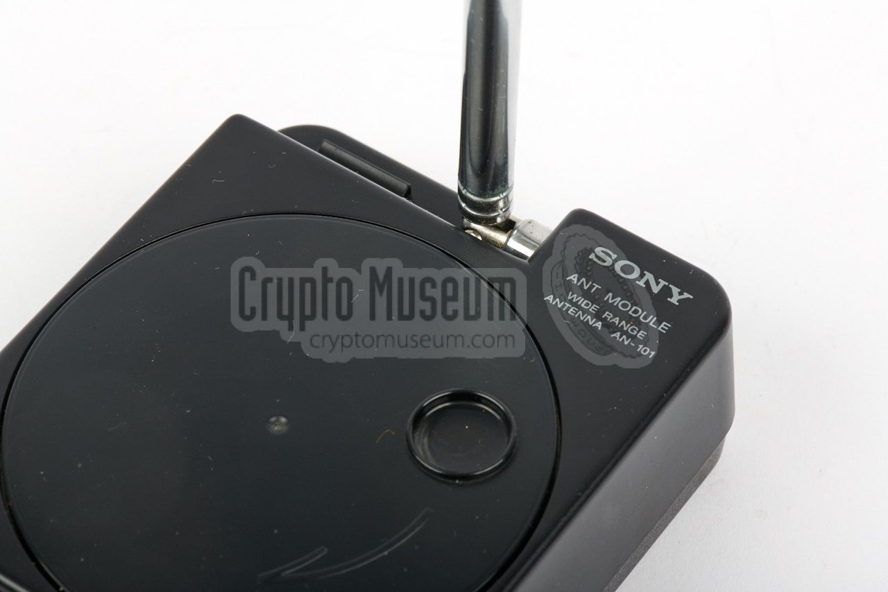
Wide range antenna
AN-101
|
|
|
In order to receive much of the short wave radio band activity without
the need for a cumbersome outdoor long wire antenna, the ICF-SW1 came
with an active antenna, consisting of a wideband amplifier and a telescope
antenna.
When using the active antenna, place it as far away from interfering
domestic appliences as possible. When in a quiet place, an active antenna
should provide a similar signal strength to an outdoor long wire antenna.
|
|
|
When using the wide range active antenna described above,
the small control box shown in the image on the right has te be
connected between the AN-101 antenna unit and the radio.
The controller is not only used to turn the AN-101 on and off,
but also controls the -20dB attenuator. Furthermore it is used
to select the desired band (SW or LW/MW).
|
|
|
In normal use, the ICF-SW1 delivers its audio to the high-quality built-in
speaker, at the left side of the front panel. For descrete operation,
a pair of earphones can be connected to the 3 mm stereo jack at the right
side.
The earphones shown in the image on the right were supplied with the ICF-SW1,
but any other type or brand of (similar) earphones can be used as an
alternative.
|
|
|
The radio was supplied with an extensive user manual, commonly
in multiple languages (depending on the area in which the radio was sold).
It contains full operating instructions and suggestions on how to
make best use of the radio under varying circumstances.
The manual was usually stowed in the 'pocket' of the lid of the hard
plastic storage box, as shown in the image on the right.
|
|
|
|
Getting access to the interior of the ICF-SW1 is not difficult, but
requires patience and accuracy, as the entire construction is rather
small. The rear case shell can be taken off by removing three screws
from the rear: two long ones that are clearly visible, and a third that is
hidden under the silver volume knob. Pull-off the knob and remove the plastic
self-adhesive foil and the screw.
|
Now use your fingernail to slide through the rig between the two case halves.
Eventually the rear case shell should come off. Inside the radio is a black
plastic frame that holds three the PCBs.
The frame is held in place by four screws: two in the battery compartment
and two that also hold the telescopic antenna. Remove these 4 screws.
Also remove the L-shaped black plastic isolation to the right of the centre
and desolder the black and grey wires underneath it. The grey wires are
connected to ground, whilst the two black wires go to the speaker.
They have to be refitted later.
|
|
|
|
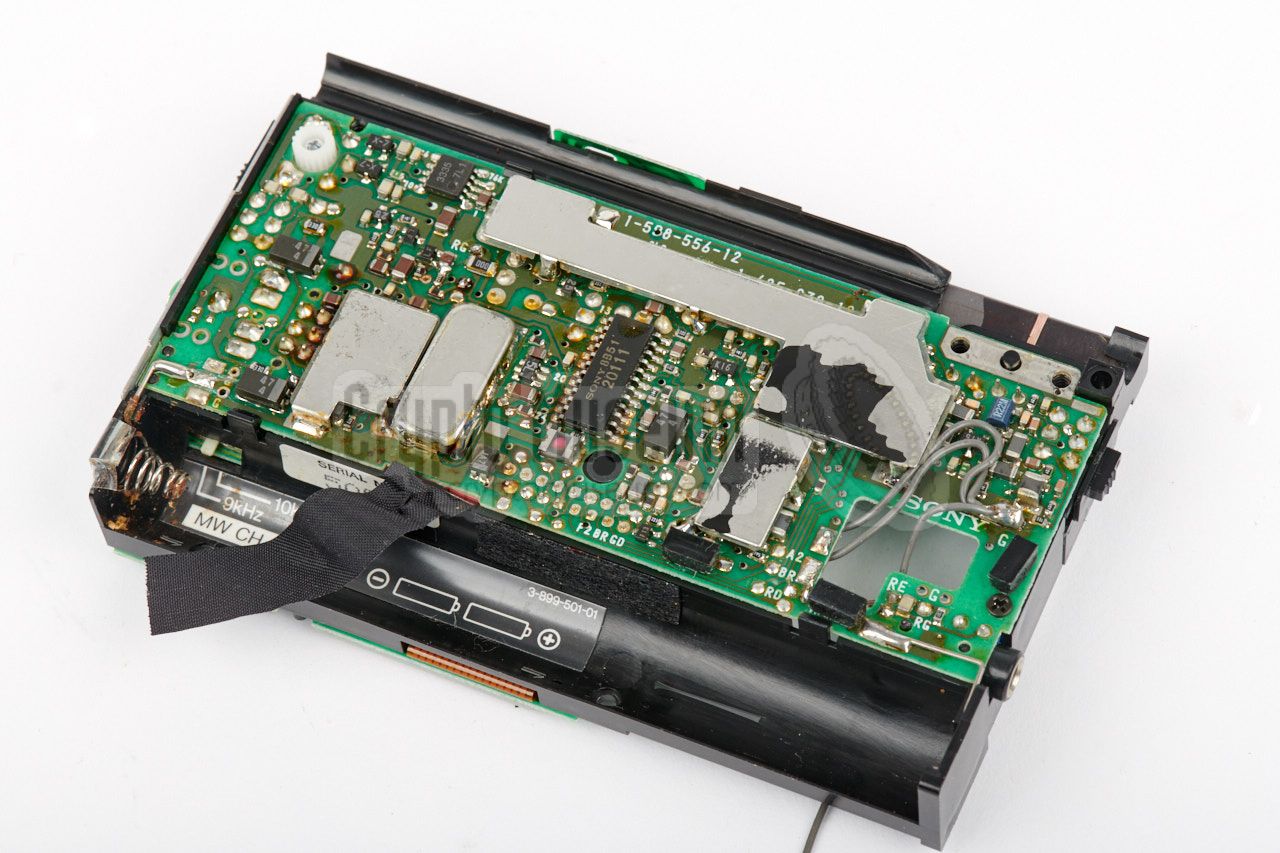
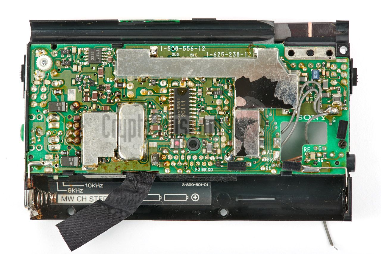
The largest PCB (i.e. the one that is visible when the rear cover is taken
off) is the main board. It holds the actual receiver that consists of various
RF, IF and AF sections, and has components at both sides. The two other boards
are smaller and hold the keyboard and the control board.
Turn the plastic frame over to take a look at
the keyboard. It is held in place by three small screws: two at the lower edge
and one at the right. Remove these screws and fold down the keyboard PCB.
|
Be careful as a small 90° PCB is soldered to the top of the keyboard.
It holds the push-button of the light switch. After lifting the keyboard PCB,
the control board is exposed. It is held in place by three small screws:
two at the right (at either side of the flex wiring) and one at the lower edge
(to the left of the flex wiring at the bottom).
After removing these three screws, the control board can be folded away
and the upper side of the main board is revealed. The control board is connected
to the main board by means of flex wiring that ends in a socket on the main
board.
|
|
|
|
If necessary, the control board can be disconnected from the main board.
This allows repair of the main board, which — after 30+ years — is most
likely to be necessary, as the board contains bad quality electrolytic
capacitors that will be leaking by now. Detailed repair instructions below.
|
|
Bringing an old ICF-SW1 back to life can be difficult. Like many other
Sony devices, the SW1 seems to have a built-in lifetime, causing the
device to stop working after a number of years. In this case, the limited
lifetime is caused by a large number of
bad quality electrolytic capacitors.
|
The problem is typical for electronic equipment that is built in the 1980s
and 1990s and is also encountered with other brands of the era. Due to a
problem with the chemical substance (the so-called electrolyte), they have a tendency to start leaking after a number of years. The electrolyte then
disappears into the radio and the capacitors lose their capacity and, hence,
their function.
With the ICF-SW1, all electrolytic capacitors are affected by this problem.
The result will be the absence of an audio signal or, in some cases, a very
soft or unstable or cracking audio signal.
|
|
|
|
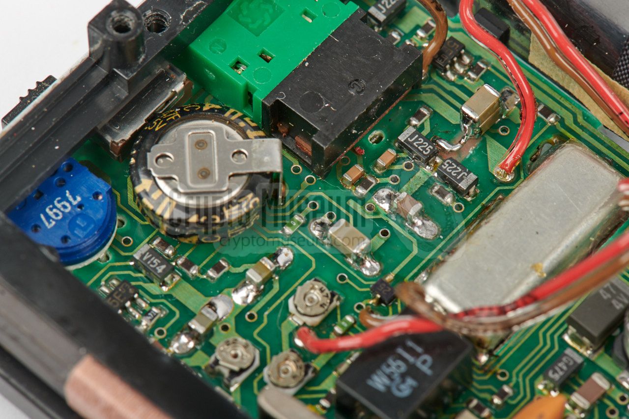
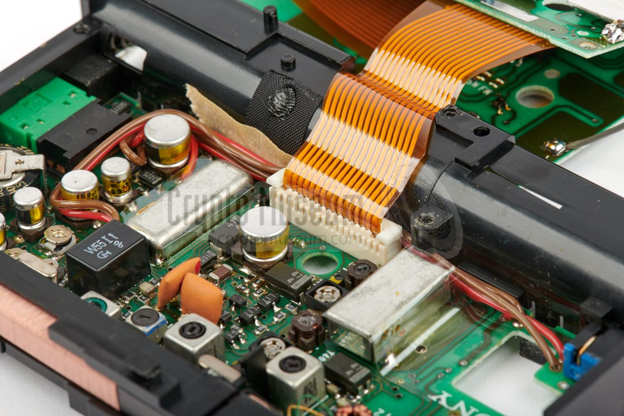
The problem can be fixed by replacing all electolytic capacitors, both on
the RF board and on the audio board. Even if your radio appears work fine,
it is recommend to replace these capacitors as they will eventually leak
chemicals into the radio, which might cause (irreparable) damage.
The image above shows part of the RF board on which the electrolytic capacitors
have been swapped. Note that we have replaced all of them
by modern high-quality long-life ceramic alternatives.
|
The receiver can be powered by internal batteries (installed
at the rear), but also by an external 3V DC power source that can be connected
to the power socket at the right side. Note that the (+) terminal is connected
to the sleeve, which is different from most other domestic equipment.
|
System FM: Superheterodyne, AM: dual conversion superheterodyne Frequency ➤ See versions Antenna Built-in ferrite antenna, built-in telescopic antenna, active antenna Output 250 mW (8Ω) Recording 0.775 mV (-60dB), 1000Ω (mini-jack) Headphones 18 Ω stereo (mini-jack) Power 3V DC from batteries or external source Batteries 2 x 1.5V AA-size penlight (12 hours) Dimensions 118.2 x 71.4 x 23.7 mm (including parts and controls) Weight 230 grams (with batteries)
|
-
Not with Australian model.
-
Not with UK model.
|
- ICF-SW1, Service Manual
Sony Corporation. 9-953-088-11. February 1988.
- ICF-SW1, Service Manual (revised)
Sony Corporation. 9-953-088-12. December 1988.
|
|
|
|
Any links shown in red are currently unavailable.
If you like the information on this website, why not make a donation?
© Crypto Museum. Created: Thursday 05 October 2017. Last changed: Wednesday, 05 November 2025 - 12:12 CET.
|
 |

|
|
|
|