|
|
|
|
|

|
|
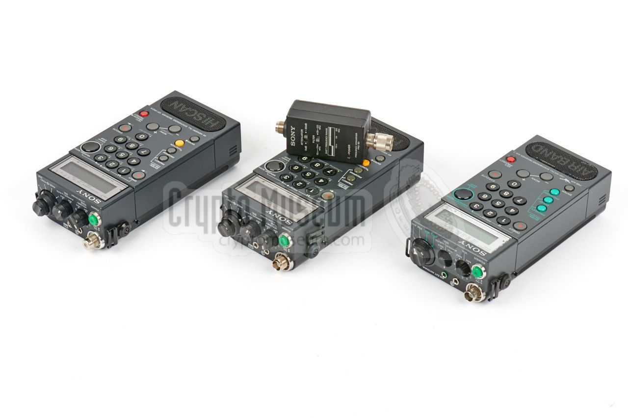
Receiver OWVL Cold War Sony
Portable short-wave receiver
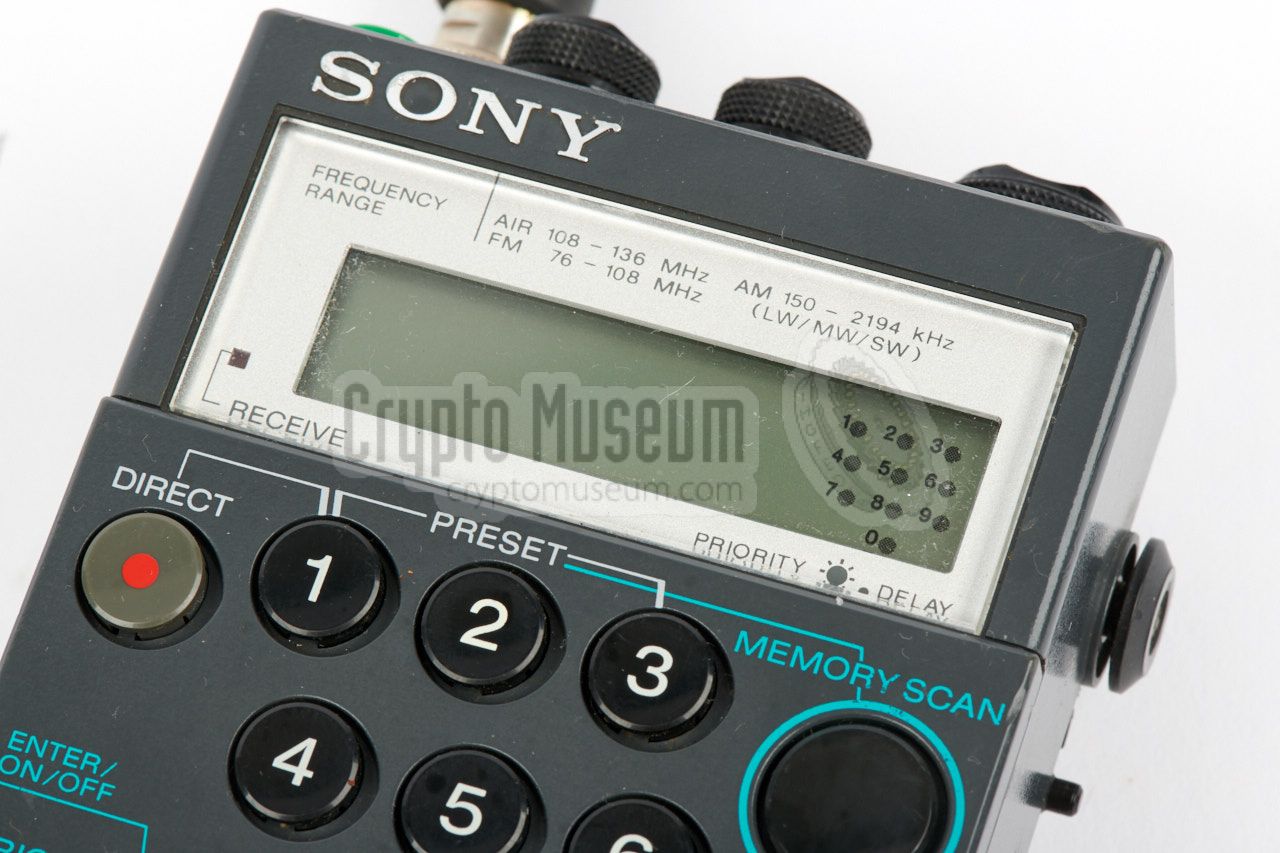
ICF-PRO70 and ICF-PRO80 are portable solid-state
LW, MW, SW and FM receivers,
also known as travel receivers, introduced around 1987 by
Sony in Tokyo (Japan).
Although they were intended for the civil market, they were
often used by spies and agents for reception of
Numbers Stations.
|
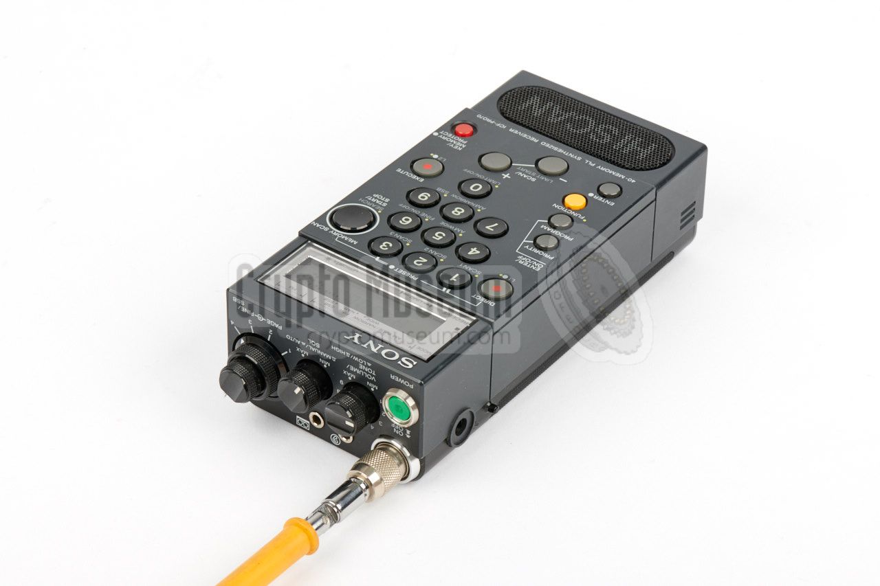
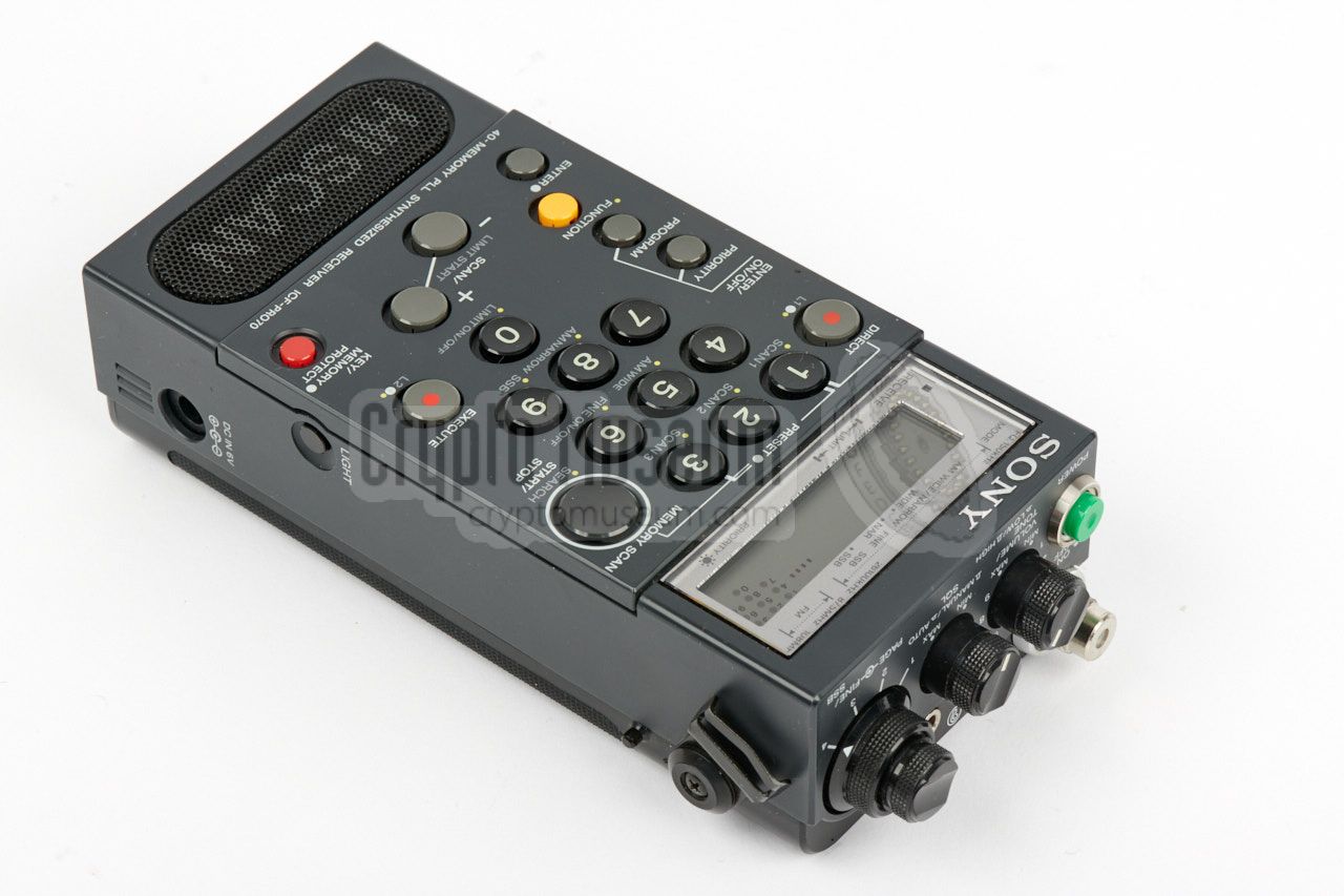
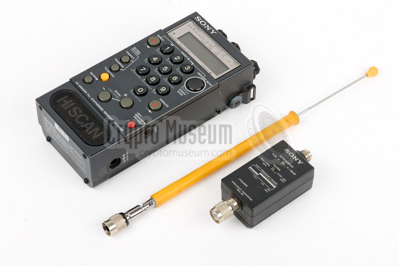
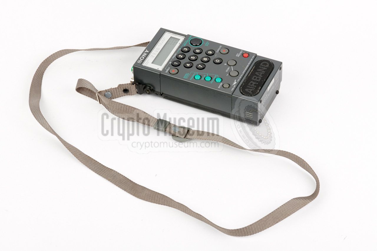
The receiver has the shape of a handheld radio, and has controls at the
front and at the top.
A relatively large high-quality speaker is present
at the bottom of the front side. User interaction is via the keyboard and
the liquid crystal display (LCD),
both of which are placed at the front.
Other controls, such as squelch, volume and power are at the
top panel,
which also holds a socket for connection of the telescopic antenna
that was supplied with the kit. Note that on the PRO70, the antenna has
to be mounted in the socket before the receiver can be switched on. 1
|
|
|
This is caused by a power switch that is embedded in the antenna
socket. This switch is omitted from the PRO80, which features a normal
TNC socket and therefore allows the connection of an external antenna.
The ICF-PRO70 was a popular receiver for short wave (SW) listeners
during the mid-1980s, although German customers faced
restrictions in
frequency range - imposed by the German authorities - as a result of
which many amateurs bought their PRO70 receiver abroad.
The ICF-PRO80 did not have these restrictions and also covered the
VHF-H band, by inserting a frequency converter between the
antenna and
the receiver. Needless to say that the receiver was also suitable for
Cold War spies and agents for the reception of the mysterious
numbers stations.
|
-
On a later variant of the PRO70, the proprietary socket was replaced
by a standard TNC socket.
|
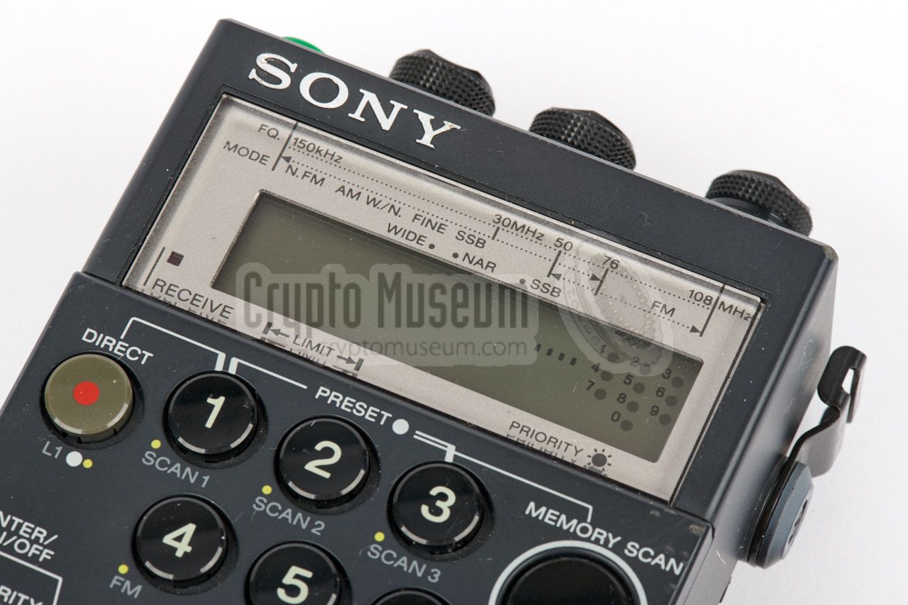
The diagram below provides a quick overview of the controls and
connections of the ICF-PRO70 and PRO80. The large and clear
keypad at the front is used for entering frequencies directly and
for controlling the scanning features. Visual feedback is provided
by a clear LCD display
that is located above the keyboard. The receiver is turned on by
mounting the original yellow antenna
in the antenna socket and pressing the recessed green power
button at the left of the top panel.
Apart from the power switch, the top panel also holds the volume
and squelch control, both of which can be depressed. When the volume
control is depressed, a hi-cut tone filter is enabled. Pressing
the squelch control enables auto-squelch. At the far right is a
4-position memory bank selector, with a fine tuning knob at the
center. Power is provided by four 1.5V AA-size penlight batteries,
installed in a battery pack at the rear,
or by an external 6V DC battery source or PSU.
|
- ICF-PRO70
This is the original travel receiver described above.
The design is based on the Sony AIR-7 (see below) and it was
available in three different versions in order to meet
the restrictions of the governing laws in certain
countries, in particular in West-Germany (BRD).
The PRO70 had a proprietary antenna socket, but later units
were fitted with a TNC socket.
- ICF-PRO80
This is basically the same receiver as the ICF-PRO70, but with
the addition of the FRQ-80 Frequency Converter,
which extends the frequency range with the VHF-H band (115.5-223 MHz).
This includes the 2m amateur band (144-146 MHz) and the maritime VHF
band. The PRO-80 was fitted with a standard TNC antenna socket,
and has an extra (hidden) switch. 1
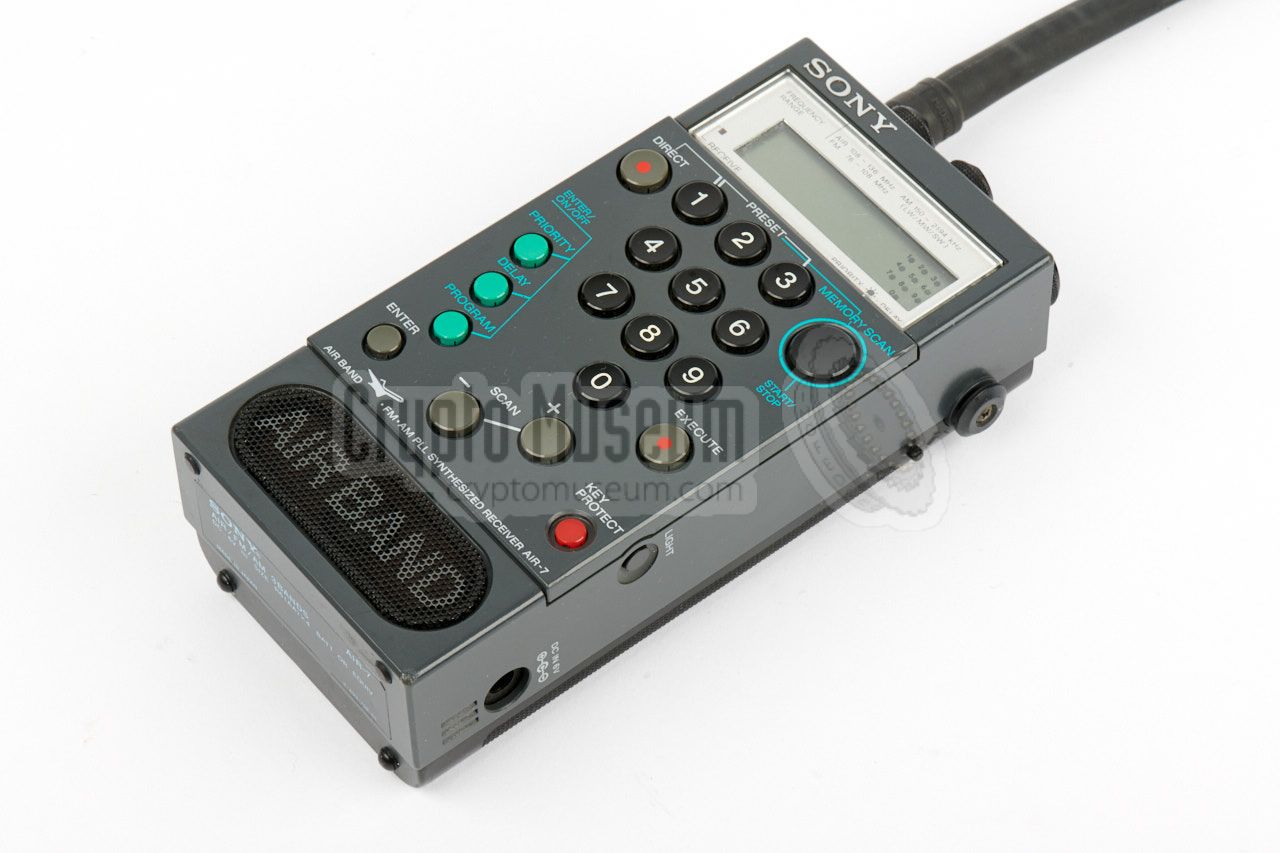
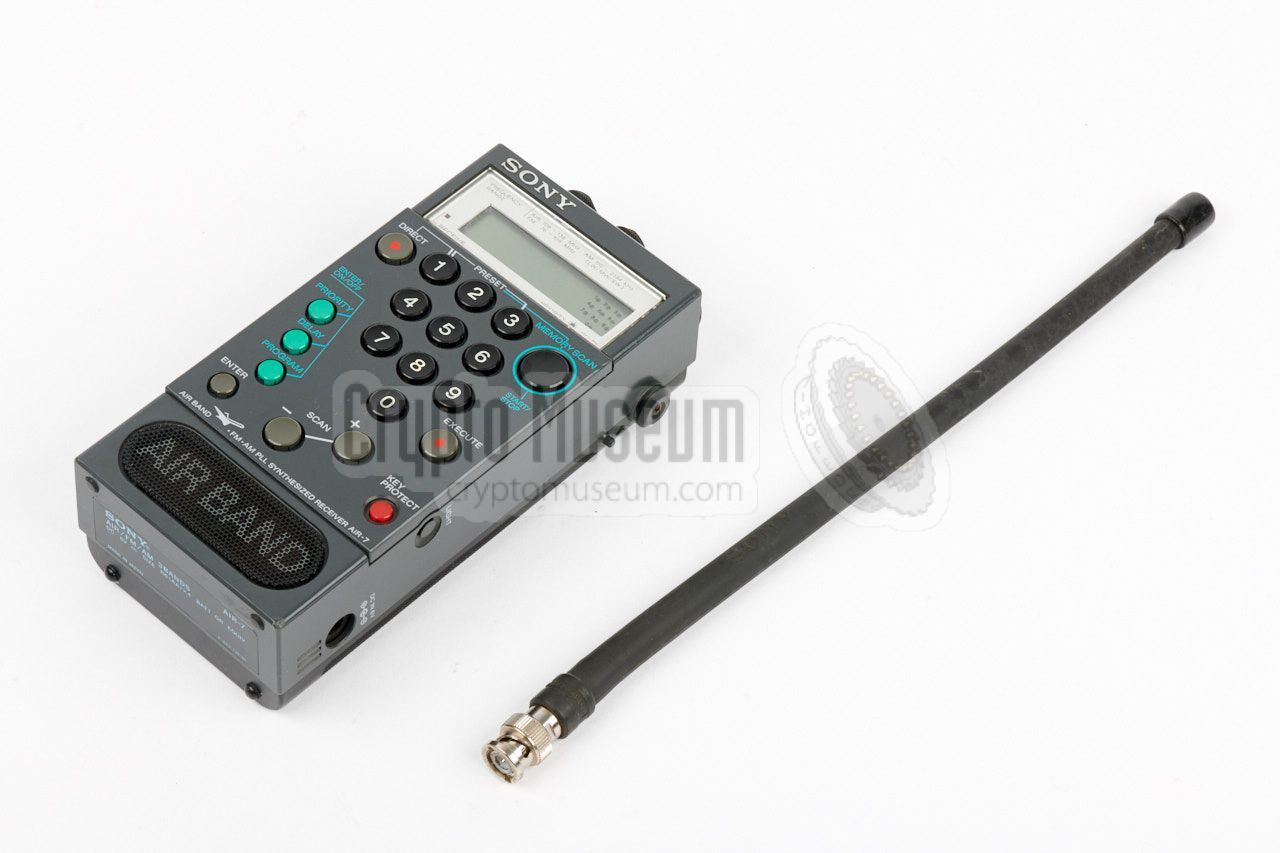
- AIR-7
This is a portable scanning receiver, specifically designed for
reception of the AIR bands. It was released in 1985 and can also
receive the FM broadcast band, plus the LW and MW bands, and part
of the SW band (up to 2194 kHz). A standard BNC antenna socket
is present. The same enclosure was later used
with the ICF-PRO70 and ICF-PRO80 [2].
|
 |
| Model | Frequency | Remark |
|
|
| ICF-PRO70 Type 1 | 150 kHz - 108 MHz | Export version | |
| ICF-PRO70 Type 2 | 150 kHz - 29.995 MHz, 87.6 - 108 MHz | European version |
| ICF-PRO70 Type 3 | 150 kHz - 26.100 MHz, 87.6 - 108 MHz | German version |
| ICF-PRO80 | 150 kHz - 108 MHz + 115.15 - 223 MHz | with Frequency Converter |
|
The AIR-7 (and AIR-8) predates the PRO70 and PRO80 models.
It was introduced in 1985 and is built with older technology 1
which is why in some respects these devices last much longer.
The AIR-7 receiver covers the AM broadcast band (150-2194 kHz),
the FM broadcast band (76-108 MHz), the air band (108-137 MHz)
and the 2 meter VHF-H band (144-175 MHz).
The AIR-8 offers the same frequency bands, but
with the upper limit of the air band at 138 MHz [2].
The following bands are available:
|
|
|
| Band | Frequency | Modulation | Remark |
|
|
| AM | 150 - 2194 kHz | AM wideband | - |
| FM | 76 - 108 MHz | FM wideband | 87.6-108 on some versions |
| AIR | 108 - 137 MHz | AM narrowband | 108-138 MHz on the AIR-8 |
| PSB | 144 - 175 MHz | FM narrowband | Not on all versions 2 |
|
Note that the 2-meter Public Service Band (PSB) is not available on
all models.
You can find out which version you are dealing with, by checking the
band selector at the top right. If it has four positions, you have the
full four-band version. Note that on some variants, the band selector has
four positions although only three are visible on the top panel.
In that case the PSB is hidden. 2
|
-
The electronics of the AIR-7 are built on pertinax PCBs,
whilst the PCBs of the PRO70 are made of (better) epoxy.
The electrolytic capacitors of the AIR-7 are of the older
conventional type and do not suffer from the leakage problems
that affects all electrolytic capacitors of the PRO70
and PRO80.
➤ More
-
A three-band version can easily be converted into a four-band
version by removing a small screw
from the frame, just behind the band selector knob. This screw simply
limits the number of steps of the selector.
|
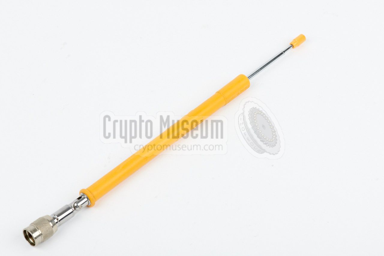
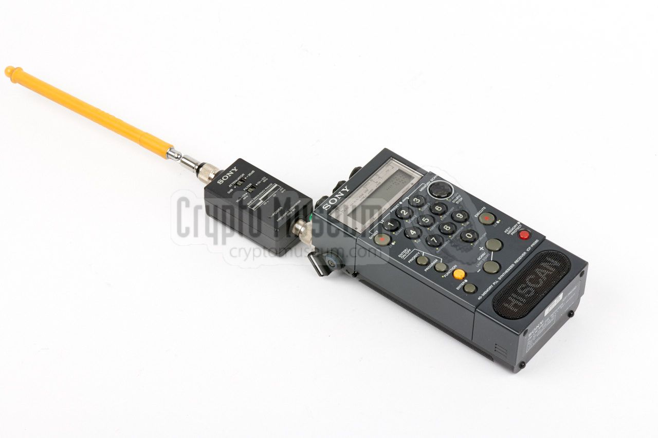
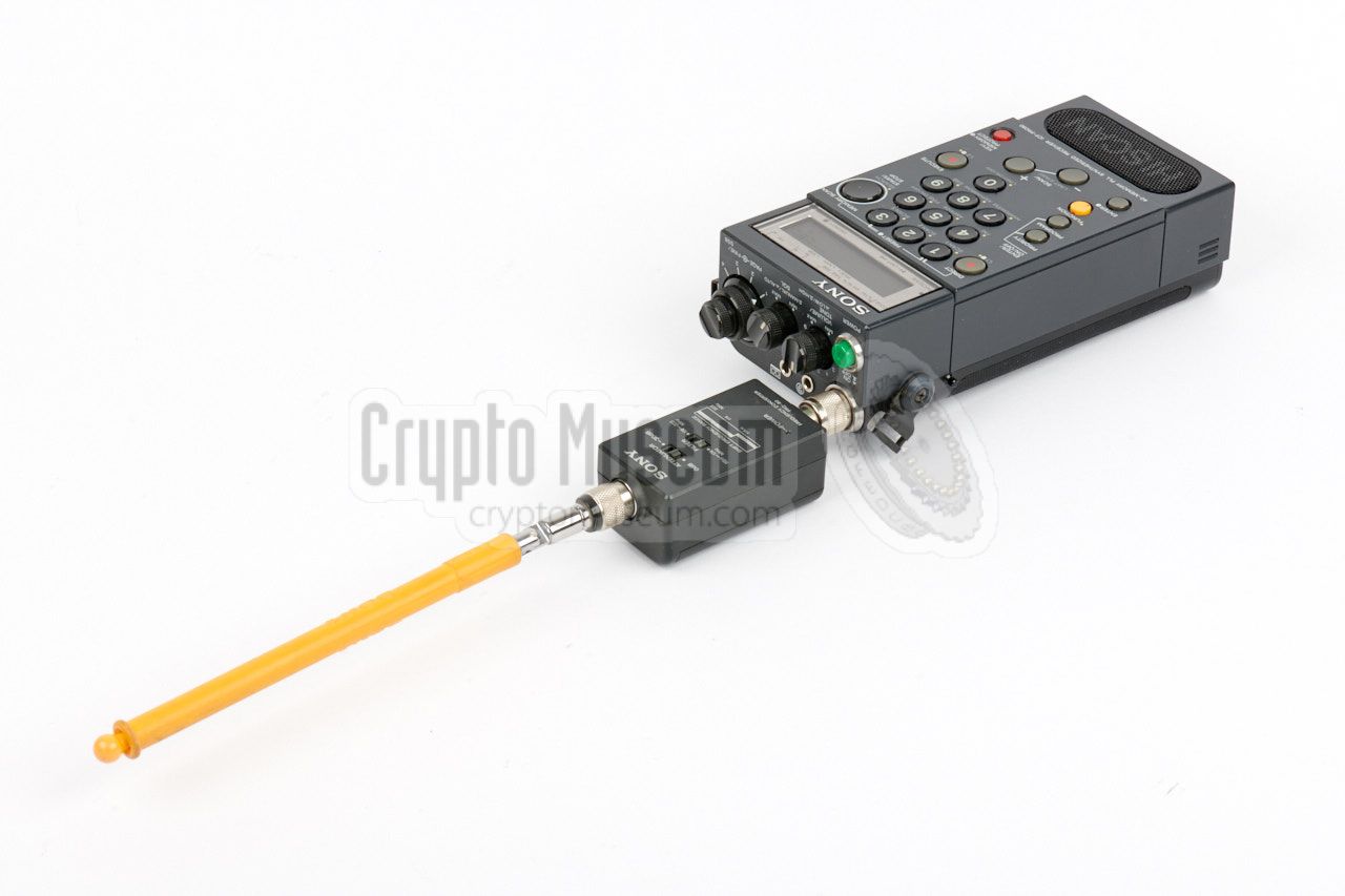
Each receiver was supplied with a telescopic antenna that is
encapsulated in bright yellow rubber, embossed with the Sony logo.
The antenna has a knee joint
that allows it to be adjusted
for the best possible reception without moving the radio around.
At the bottom is a screw-connector that fits the antenna socket of
the radio. Note that the socket of the PRO70 is different from the
one on the PRO80. The socket of the PRO70 has a built-in power switch,
which is omitted from the PRO80.
|
|
|
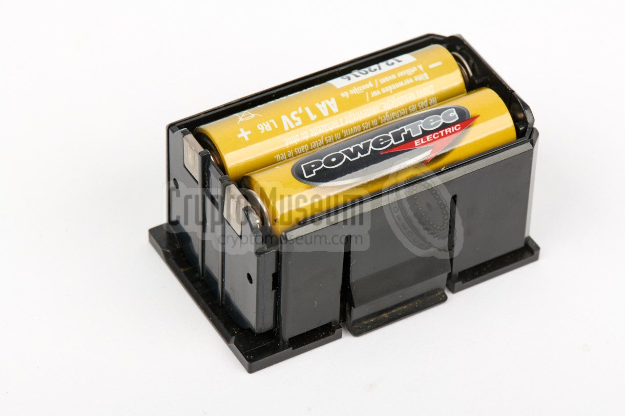
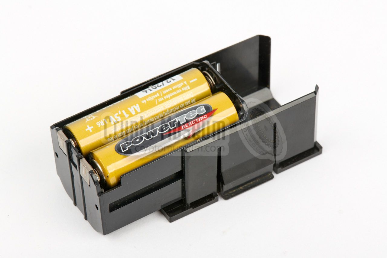
The receiver can be powered by internal dry batteries, that are installed
as a block at the rear. The block can easily be removed and holds four
1.5V AA-size penlight cells, as shown here.
It is also possible to power the radio from an external 6V DC source,
that can be connected to the power socket at the right side.
Note that the PRO70 can only be switched on when the antenna is installed.
This is caused by a switch in the base of the antenna socket.
|
|
|
The ICF-PRO70 was usually supplied with a miniature earphone, such as the
one shown in the image on the right. It has a 50 cm cable with a 3.5 mm
mono jack at the end, that mates with the earphone socket on the top panel.
The receiver can be used with virtual any type of earpiece that has a
similar connector. When it is plugged-in, the internal speaker is switched
off.
|
|
|
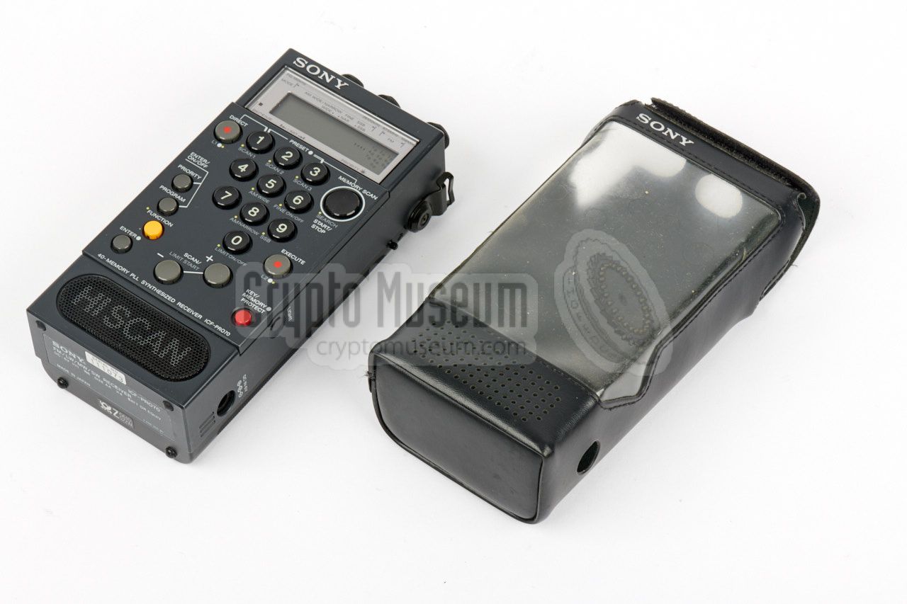
To protect the radio against dust and rain, the soft carrying case
shown in the image on the right was supplied with each unit.
It has a large transparent section at the front through which the
keyboard and display are visible. The flap at the top is held in
place by a Velcro strip.
Although this case offers some protection, most users found it
more comfortable to operate the radio outside the carrying case.
|
|
|
Apart from the soft carrying case shown above, each radio was also supplied
with an adjustable shoulder strap that could be fitted to the metal
brackets at the sides of the radio (near the top).
This way, the shoulder strap remains attached to the radio, even when
the soft carrying case is not used. If you don't want to use the shoulder
strap, the metal brackets can easily be removed.
|
|
|
|
|
Frequency Converter
ICF-PRO80 only
|
|
|
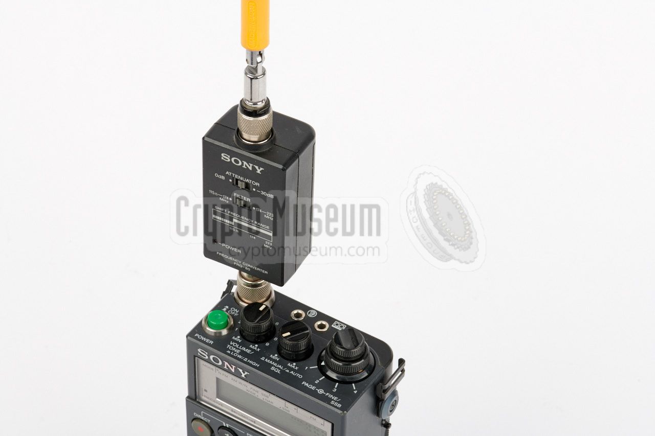
The frequency range of the ICF-PRO80 can optionally be expanded with the
VHF-H band, which runs from 115.5-223 MHz, by inserting the FRQ-80
Frequency Converter between the antenna and the antenna socket, as shown
in the image on the right.
Note that the frequency converter is powered by two internal 1.5V AA-size
batteries. When using the converter, a hidden switch inside the battery
compartment has to be toggled in order to enable
the extended frequency range.
|
|
|
|
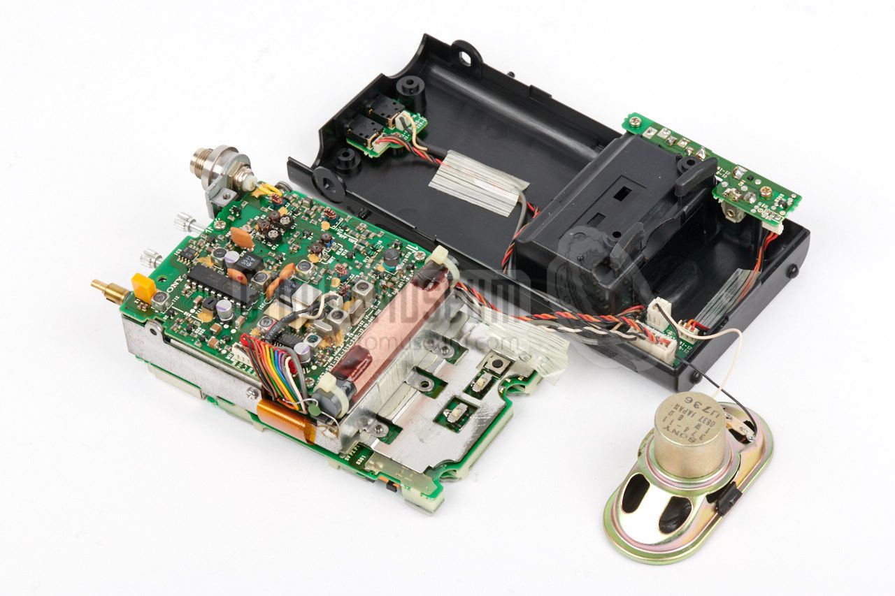
Getting access to the interior of the ICF-PRO70 and ICF-PRO80 is
easy and requires the removal of six screws: two at the sides
(holding the brackets for the shoulder strap), two at the rear
(close to the top) and two in the battery compartment
(visible after removing the battery pack).
|
Once the screws are removed, the rear plastic black case shell
can be taken off. When doing this, you may have to desolder a
capacitor that is connected to one of the terminals of the
battery compartment. Note that the knobs do not have to be
removed from the top panel adjustments. They are
better left in place to avoid stress on the potentiometers
when refitting them again.
The receiver is mounted to the front half of the case, by means
of two screws, one at the top (close to the top panel) and
one at the center of the battery area (just below the ferrite
antenna).
|
|
|
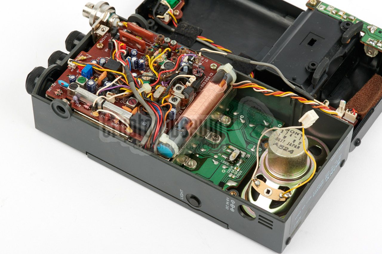
The smallest board
is the actual receiver (the RF board).
It is visible in the image above. At the other side of the stack
is the control board that holds the keyboard. In between these two boards
is the audio board.
Remove two screws from the sides of the metal
frame to expose the audio board, as illustrated in the image on
the right.
Note that there is a lot of wiring between the two boards and
to other parts of the radio. All wiring is fixed in place and
cannot be removed easily. Be careful not to damage any of the wires
when moving the PCBs around as part of a repair job.
|
|
|
|
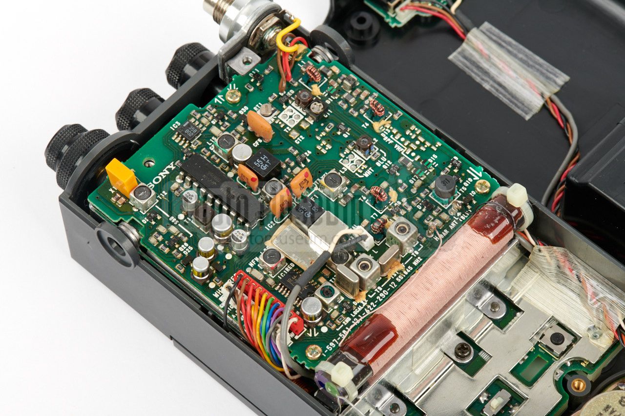
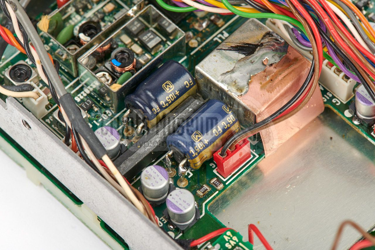
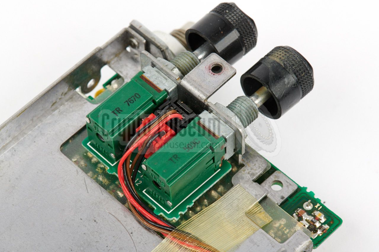
The potentiometers for volume and squelch control, are mounted on a
small carrier board that is fitted to the
frame at the bottom of the RF board. It is wired to the audio board.
With equipment of this age (30+ years), it is likely that a repair
is necessary in order to bring it back to life again. In fact, due to the
use of bad quality electrolytic capacitors in the design, it is nearly
certain that the receiver no longer works by now.
Suitable repair directions are provided in the section below.
|
|
Bringing an old ICF-PRO70 back to life can be difficult. Like many other
Sony devices, the PRO70 seems to have a built-in lifespan, causing the
device to stop working after a number of years. In this case, the limited
lifetime is caused by a large number of
bad quality electrolytic capacitors.
|
The problem is typical for electronic equipment that is built in the 1980s
and 1990s and is also encountered with other brands of the era. Due to a
problem with the chemical substance (the so-called electrolyte), they have a tendency to start leaking after a number of years. The electrolyte then
disappears into the radio and the capacitors lose their capacity and, hence,
their function.
With the ICF-PRO70, all electrolytic capacitors are affected by this problem.
The result will be the absence of an audio signal or, in some cases, a very
soft or unstable or cracking audio signal.
|
|
|
|
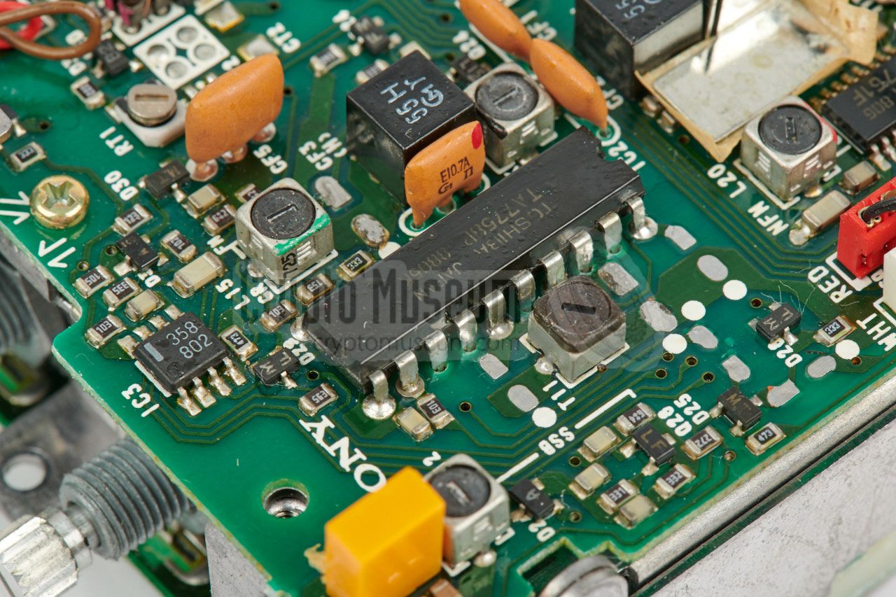
The problem can be fixed by replacing all electolytic capacitors, both on
the RF board and on the audio board. Even if your radio appears work fine,
it is recommend to replace these capacitors as they will eventually leak
chemicals into the radio, which might cause (irreparable) damage.
The image above shows part of the RF board on which the electrolytic capacitors
have been swapped. Note that we have replaced some of them
by modern high-quality long-life ceramic alternatives.
|
And whilst the radio is open, it might be good to consider the removal of
the power switch that is embedded 1 in the antenna socket of the PRO70.
This power switch is connected in series with the radio's power line.
As a result, the radio can not be switched on when the antenna
is dismounted.
Although this switch was probably added for good reasons — the radio can
not be turned on accidently during transport — in practice it was often
a nuisance. Furthermore, it disallows the connection of an external antenna.
Note that this embedded switch is not present on the PRO80.
|
|
|
|
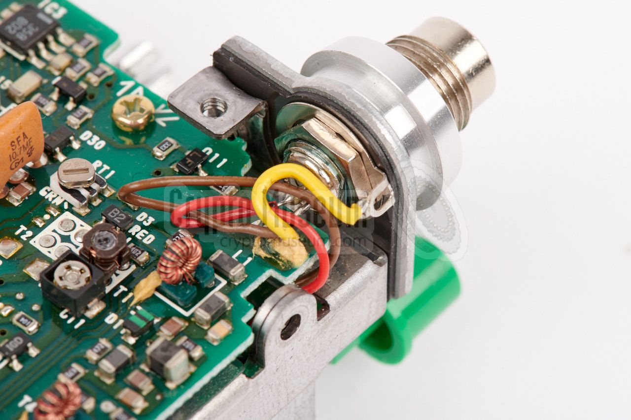
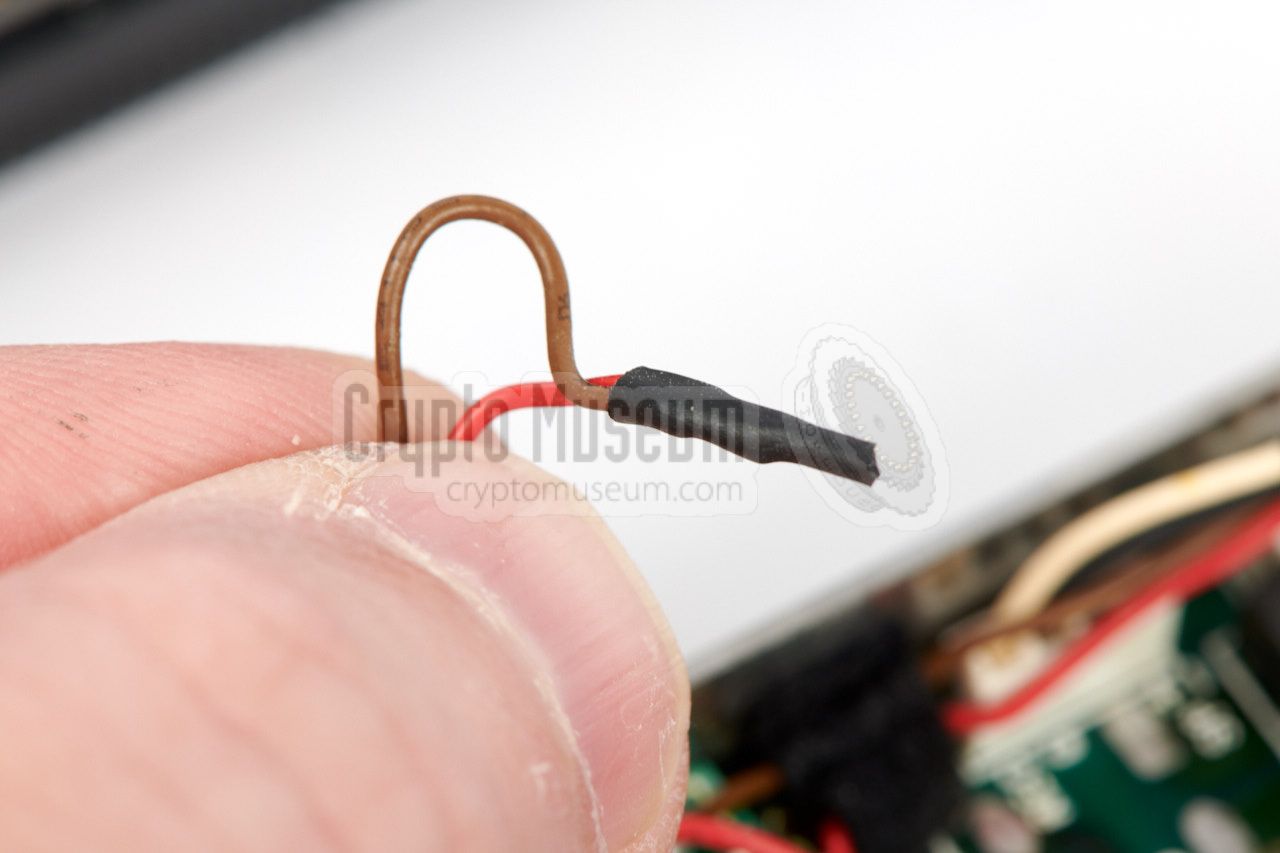
The function of the switch in the antenna socket can easily be
bypassed by desoldering the red and brown wires from the antenna
socket and soldering them together.
Use proper insulation to avoid short-cuts.
And whilst you are at it, you might want to
swap the antenna socket for a more common BNC socket, so that
it becomes possible to connect an external antenna. Note that if
you do this, the original telescopic antenna
can no longer be used, as it has a proprietary connector.
|
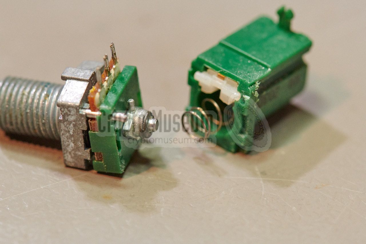
Another problem that affects many AIR-7, PRO-70 and PRO-80 receivers,
is that the potentiometers of the volume and squelch controls can
be worn out. Although these potentiometers are high-quality types
made by Alps, they are likely to be affected by many years of intensive use.
Finding identical replacement potentiometers will be next to impossible
after all these years, but it might be possible to find alternatives
that fit in the available space. Furthermore it might be possible — with
the right tools and a lot of patience — to repair the existing worn-out ones.
|
|
|
|
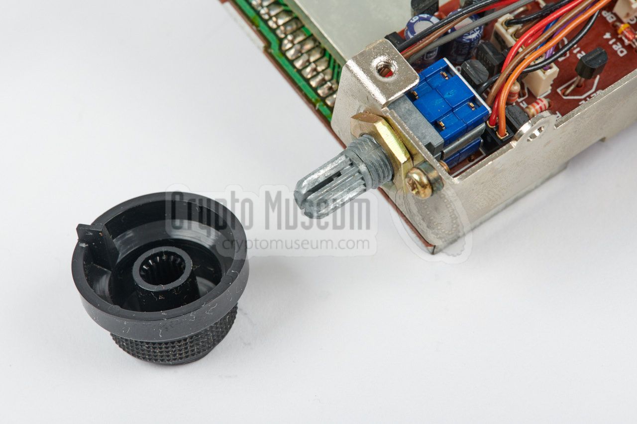
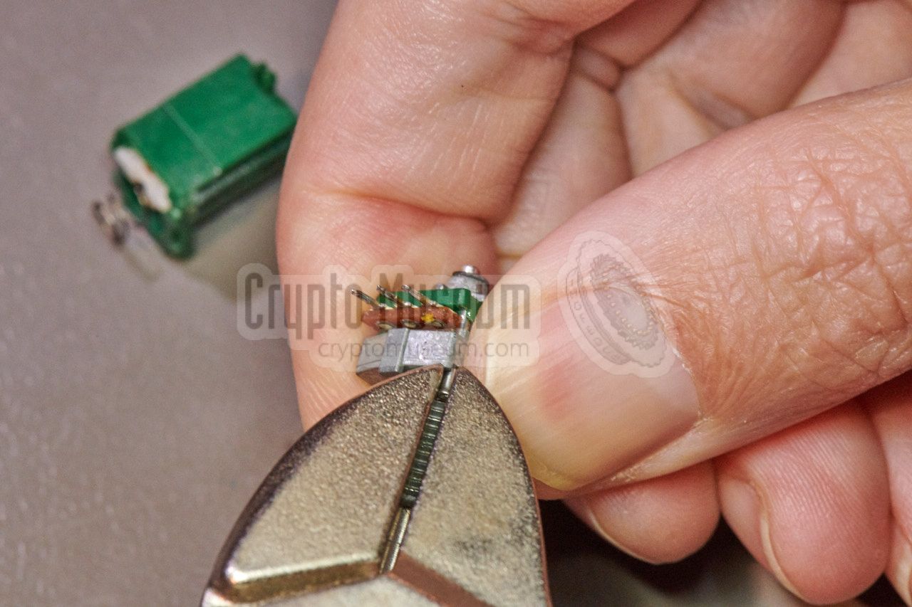
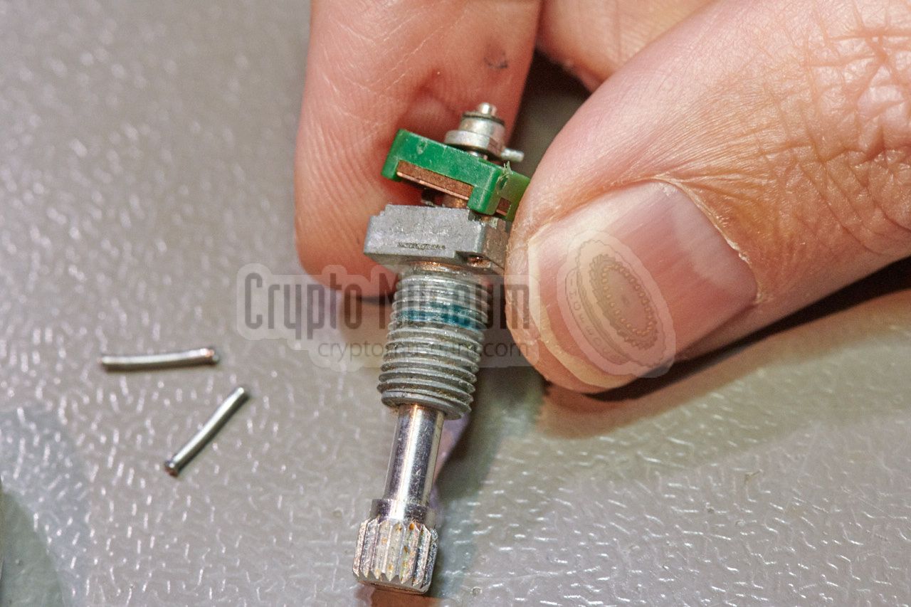
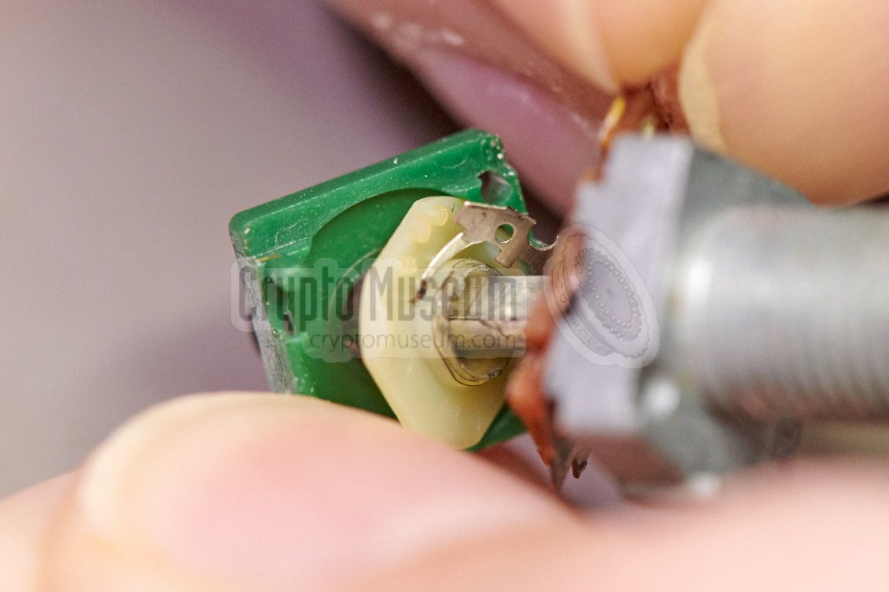
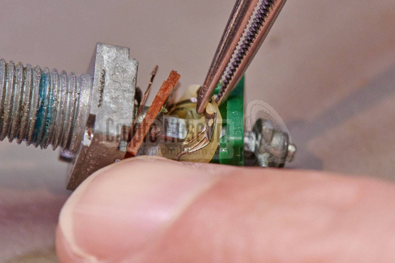
This is done by carefully milling off the rear ends of the two metal
rods that keep the potentiometer together. After
removing the two rods,
the green plastic enclosure can be taken apart.
Be careful not to lose any of the parts. The problem is that the center
contact (i.e. the slider) is
no longer attached
to the plastic disc that rotates it.
Put it back in place and
melt the plastic somewhat
(using a soldering iron) to affix it again. Then carefully
reassemble the potentiometer and
push the rods back in, to keep the parts together. Use a piece of mylar
tape to strengthen the assembly, and solder it back onto the carrier board.
The controls should now work as expected.
|
-
According to Sony, a later variant of the PRO-70 was equipped with
an TNC antenna socket, just like the PRO-80, allowing the connection
of an external antenna by using a (supplied) BNC adapter.
|
The receiver can be powered by internal batteries (installed
at the rear), but also by an external 6V DC power source that can be connected
to the power socket at the right side. Note that the (+) terminal is connected
to the sleeve, which is different from most other domestic equipment.
|
Device Portable communications receiver Purpose Hobby, Base-to-Agent communication Model ICF-PRO70, ICF-PRO80, AIR-7 Manufacturer Sony Year 1987 Country Japan Bands LW, MW, SW, VHF System Dual conversion superheterodyne Frequency ➤ see versions Antenna Built-in ferrite, external telescopic, TNC socket Audio 400 mW Output Earphone jack (8Ω) Recording Mini jack, 0.775 mV (-60 dB), 1 kΩ Power 4 x 1.5V AA battery, or external 6V DC source Life Approx. 10 hours with standard batteries Dimensions 182 x 90 x 50 mm Weight 650 g
|
|
|
Channel Spacing ICF-PRO80
|
|
|
115.150 - 115.528 MHz 3 kHz 115.531 - 116.602 MHz 9 kHz (optionally 10 kHz) 116.605 - 164.995 MHz 5 kHz 165.000 - 190.995 MHz 5 kHz (50 kHz in FM) 191.000 - 223.000 MHz 50 kHz
|
- AC power adapter AC-D4
- Rechargeable battery pack BP-23
- Car battery cord DCC-127A, DCC-120 or DCC-240
- Battery case EBP-6
- Connecting cord RK-69A
- VHF antenna AN-3
|
- ICF-PRO70 / ICF-PRO80, Operating Instructions
Sony Corporation. 3-990-095-12. 1987.
- ICF-PRO70/PRO80, Service Manual (revised)
Sony Corporation. 9-952-864-82. September 1999.
|
|
|
|
Any links shown in red are currently unavailable.
If you like the information on this website, why not make a donation?
© Crypto Museum. Created: Tuesday 03 October 2017. Last changed: Friday, 05 June 2026 - 19:37 CET.
|
|

|
|
|
| | |