|
|
|
|
|

|
|
USA CIA AT-3 → ← AS-3
The receiver is housed in a die-cast aluminium enclosure that can be
plugged straight into the right side of the AT-3 transmitter of the
AS-3 radio set. For stand-alone use, an external PSU or
a special-purpose battery can be connected to the
9-pin sub-D connector
at the left side.
The device features permeability tuning, and allows the frequency to be adjusted from 3 to 12 MHz in a single band with kHz resolution,
using the tuning knob in combination
with a 5-digit odometer-style readout
at the top surface. This is similar to that of the
German BN-58 receiver.
|
|
|
|
Development of the RR/E-11 started around the same time as that of the
AS-3 spy radio set
– in 1956 – together with a two-band version – the
RR/D-11.
The first 150 receivers (RR/E-11 and RR/D-11) were delivered
around May 1959, well before the
complete AS-3 radio set was taken into
production. It seems likely that many of the early units were
intended for stand-alone use.
|
-
The developer of the AS-3, which was probably also the developer
of the RR-E-11, is currently unknown
and has been redacted in the documentation released by the CIA [A].
However, given the fact that they were based in New Jersey, it is
possible, if not likely, that it was the
Radio Corporation of American (RCA) [2].
|
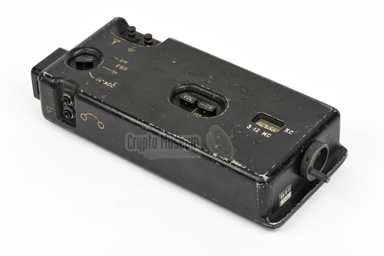
The image below gives an overview of the controls and connections on the
body of the RR/E-11 receiver. At the left is the DE-9 socket
by which it can be connected to a compatible transmitter, such as the
AT-3,
in which case power and antenna signal are provided by the transmitter.
This socket is also used for powering the receiver externally by means of
the supplied 12V cable. 1
In stand-alone configuration, antenna and counterpoise should be connected
to the push-in terminals at the top left. A pair of headphones, or a
low-impedance earphone,
should be connected to the terminals at the front
left. The device is turned on by placing the MODE selector to ON or to
ON AGC. In the latter case, the Automatic Gain Control (AGC) is enabled as
well.
The audio volume is adjusted with the VOL-knob at the centre. Turning
it clockwise increases the volume. To its right is the adjustment for the
Beat Frequency Oscillator (BFO), which is needed for the reception of
CW (morse) signals. In fully counter-clockwise position, the BFO is disabled.
The reception frequency is adjusted with the circular metal knob at the right.
It has a foldable grip and should be collapsed when stowing the receiver.
Turning the knob engages an internal gearbox that drives a set of three
coil cores, plus the odometer-style readout at the top surface.
Note that although the receiver has an accurate odometer-style frequency
adjustment, the actual frequency to which it is tuned may differ
substantially from what is shown in the window. This is particularly the
case in extremely hot or cold environments,
when it may off by > 25 kHz [A].
|
|
The MODE selector has the following settings:
|
OFF Device completely switch OFF ON Device ON (AGC disabled) ON AGC Device ON, AGC enabled
|
-
In some situations cables for connection to a 6V car battery were supplied
instead.
|
Each RR/E-11 receiver was supplied with a cable – similar to the reproduction
shown here – that allowed it to be
powered from an external 12V DC power source, so that it could be used
stand-alone (i.e. without a compatible transmitter).
The cable mates with the 9-pin socket
at the left side,
and has clips for connection to, say, a car battery.
A different cable was optionally available for use with 6V batteries.
In addion, the existing 12V cable could be modified use with 6V DC.
|
|
|
It is currently unknown what type of earphone or headphones was supplied
with the RR/E-11, but it is likely that it was similar to the earpiece
shown in the image on the right, or a pair of stethoscope tubes with
this speaker armature.
The earphone is connected to the two terminals at the front, by means of
1 mm banana-plugs, such as the ones shown here.
|
|
|
|
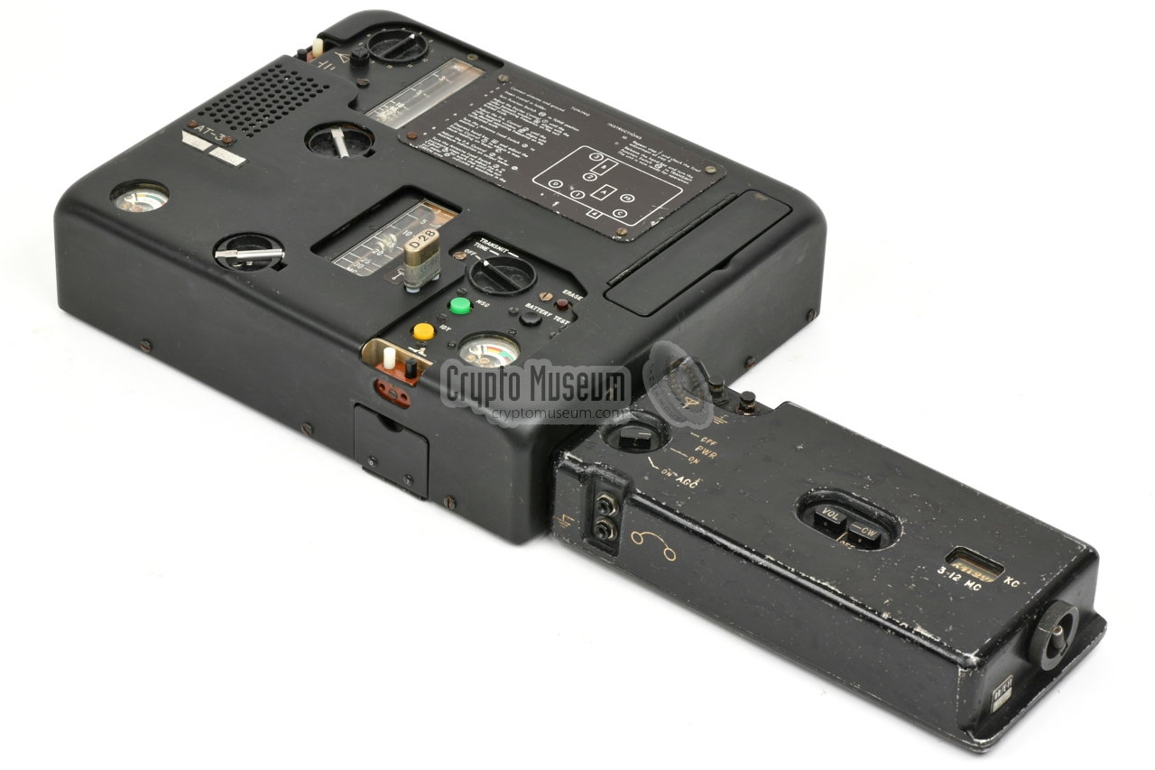
The device is housed in a die-cast aluminium enclosure that consists of two
parts: the main body which acts as the top, and a flat bottom panel that is
bolted to the main body with 8 recessed screws. After loosening them, the
bottom panel can be removed, as shown in the image above.
|
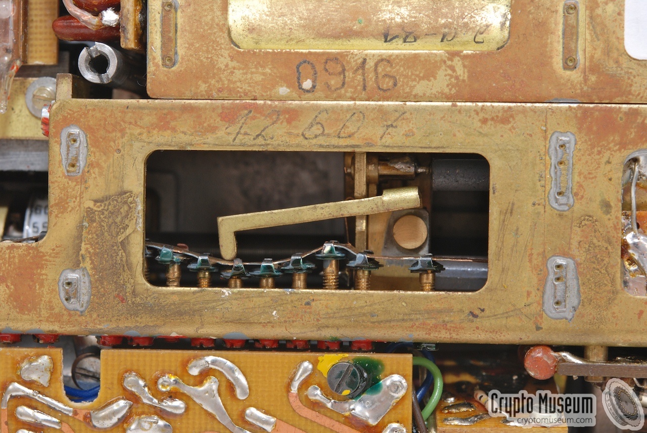
The most prominent feature of the receiver is the multi-stage permeability
tuning unit, that is fitted at the top left, and takes about 1/3rd of the
total space. It consists of three long coils of which the cores are moved in
tandem by a high-precision cogwheel-driven gear mechanism.
The advantage of permeability tuning is that it is nearly linear over the
entire 3 to 12 MHz range. The remaining errors are corrected by means of
nine adjustable stubs that form the mechanical equivalent of a correction
curve.
When adjusting the frequency the curve is traced by a 'finger'.
|
|
|
The electronic circuits are spread over 3 high-quality expoxy-based
printed circuit boards: a small one
with the power circuitry,
a larger one
with RF-stage, VFO and LO,
and a long one
with IF-stages, BFO,
AM detector, AGC and AF-stage.
The image on the right shows part of the IF-strip on the largest PCB.
The transistors – mostly early types from Philco – are fitted in a metal
clips and their legs are soldered to mounting posts at the upper edge of the
board. The boards are interconnected with teflon wiring
and are protected against moisture by a thin conformal coating.
|
|
|
|
Note that the output stage of the audio amplifier – the rightmost part of
the IF-board – contains a miniature transformer, fitted in a clip
at the upper right corner,
that allows both high- and low-impedance headphones to be used.
The audio is also available on the 9-pin socket at the left.
|
-
The BN-58
was developed by Wandel & Golterman in Germany, and had two
frequency bands: 2.5-9.1 and 9.1-24 MHz. It can be regarded as the
German equivalent of the CIA's RR/D-11
(the two-band version of the RR/E-11).
It uses a crystal-based local oscillator (LO), whereas the LO of the
RR/E-11 is free-running.
|
Below is the preliminary block diagram based on our observations whilst
restoring the RR/E-11 in our collection.
At the left are input filter, RF pre-amplifier, first mixer and band filter,
all of which are adjusted in tandem when turning the frequency tuning knob
at the right side.
The signal from 2nd mixer is passed to a multi-stage IF-strip, via a
mechanical filter that is mounted between the RF and IF boards.
It is visible as a long cilinder when
looking at the interior from the bottom side.
A Beat Frequency Oscillator (BFO) is present for the reception of CW
(morse) signals.
Its signal is injected somewhere in the IF-strip, and can be suppressed
by turning its adjustable capacitor fully counter-clockwise, in which case its
blades are shorted by a small contact strip.
At the top right is the power circuit, part of which converts an external
12V supply to the internal 6V DC.
|
|
When we obtained the RR/E-11 featured here – in June 2020 – it was not in
working condition. In fact, when connected to a 12V (or 6V) power source, it
consumed approx. 10 mA, but was otherwise dead. No sound in the headphones.
At first sight, the interior seemed to be in original state, but a closer
inspection revealed that there had been earlier (failed) attempts
to repair the unit.
|
The tuning unit had been removed, and in the processed of doing so, two
of the wires to the tuning coils had come off. But apart from that,
all parts were still present and were originals.
After a suitable 12V cable
was made for the 9-pin socket at the left,
it was powered up for the first time. Although 6V was present at the MODE
selector, none of the transistors on the RF and IF PCBs was supplied with
a sensible voltage, which led to the conclusion that something was wrong in the
power circuit.
It turned out to be a broken germanium diode on the
small power board.
|
|
|
|
This board is fitted in front of the IF-strip, close to the front edge of
the enclosure, and can easily be removed.
The diode was replaced by a universal AA119 germanium diode, and the device
was tested again. This time it worked, and was even receiving signals,
but a new problem emerged.
|
An annoying 'motor boat' sound could be heared through the headphones, even
with the volume fully turned down. And with the oscilloscope it was clearly
visible on power rail of the IF-board.
It turned out to be an
unwanted oscillation effect in the power circuit,
probably caused by ageing of the components, and was fixed by placing a
low-ESR electrolytic capacitor between the power rail and ground.
By soldering it directly to the terminals of the red and black wires on
the small power board shown above,
it turned out to be effective and could easily be hidden from view.
|
|
|
|
After this modification, the receiver was stable and was able to demodulate
the signal from our test generator, which was running at 6 MHz. It was
insensitive though, and the scale was approx. 200 kHz off as well. The
sensitivity problem was caused by the
broken wires of the tuning coils.
|
As a result, the band filter between the first and second IF mixer was not
aligned in tandem with the variable frequency oscillator (VFO), resulting in
poor signal strength. Luckily it was possible to deduce where the broken wires
had once been soldered to, and after refitting them to the upper right coil,
the filter was once again operational.
It was unclear why the scale was so far off. It is known from
CIA documentation that at very low or high temperatures,
the frequency can be off by > 25 kHz [A], but that does not explain
the observed 200 kHz error at room temperature.
|
|
|
It seems therefore likely that during an earlier repair attempt, the
odometer-style
scale had been turned whilst the tuning meachanism and its gearbox had been
removed temporarily from the enclosure. By loosening the clamp to the left
of the big cogwheel, the scale could be turned without moving the tuning coils,
and was roughly set to the desired position. The clamp was then fastened again,
and the remaining error was corrected by readjusting the local oscillator (LO).
In the process of restoring the receiver, the following has been done:
|
- Rubber feet replaced
- Black ink removed from front panel
- Diode replaced in power circuit
- Capacitor replaced in power circuit
- Tuning coil L1 rewired
- Scale calibrated (was 200 kHz off)
- Local oscillator calibrated
- Tuning gear box oiled and greased
- 12V power cable added
- Headphones added
|
|
At the left side of the RR/E-11 receiver
is a rectangular metal stub with an embedded 9-pin D-type male
connector. When the receiver is used as part of the AS-3 radio set,
this part is
plugged into the right side
of the AT-3 transmitter.
In that case, power and antenna signal are supplied by the transmitter.
In addition the (line) audio output of the receiver is available on
this connector. It is passed by the transmitter to the (optional)
TP-3 printer (that can be plugged into the left side).
|
- Antenna
- Ground
- n.c.
- n.c.
- Jumper to 6 when used with 12V DC
- +6V DC input
- n.c.
- +12V DC input
- Audio output
|
|
Frequency 3 - 12 MHz Modulation Phone (AM), Morse (CW) Power 6 or 12V DC
|
-
Partly declassified on 29 May 2014. CIA-RDP78-03330A000600460001-0.
|
- Louis Meulstee, RR/E-11
Wireless for the Warrior - Volume 4 Supplement, Chapter 142.
October 2017. Retrieved June 2020.
- Pete McCollum, The AS-3 HF Radio Set
Personal correspondence. Retrieved June 2020.
- H. Keith Melton, CIA Special Weapons & Equipment: Spy Devices of the Cold War
New York, 1993. ISBN 0-8069-8732-4. Page 19.
- CIA, RR/E11
Date unknown.
Partly declassified on 29 May 2014.
CIA-RDP78-03330A000600460002-9.
|
|
|
|
Any links shown in red are currently unavailable.
If you like the information on this website, why not make a donation?
© Crypto Museum. Created: Saturday 27 June 2020. Last changed: Thursday, 20 April 2023 - 13:53 CET.
|
 |

|
|
|


