|
|
|
|
|

|
|
USA CIA SBO RR/E-11 → ← AS-3
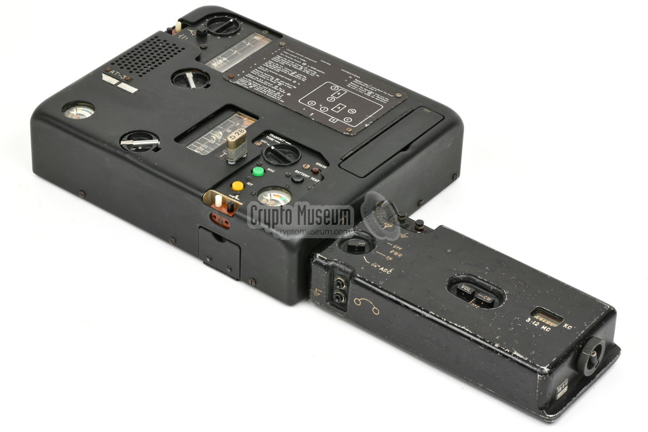
The transmitter measures approx. 26 x 22 x 6 cm 3 and weighs 3.5 kg.
It has a frequency range from 3 to 30 MHz and produces an output power
of no less than 25W in CW. It is the first
CIA transmitter with a built-in
burst keyer, that allows pre-recorded (encrypted)
messages on a magnetic tape
to be played back at high speed, in order to reduce the risk of
interception and discovery
by means of Radio Direction Finding.
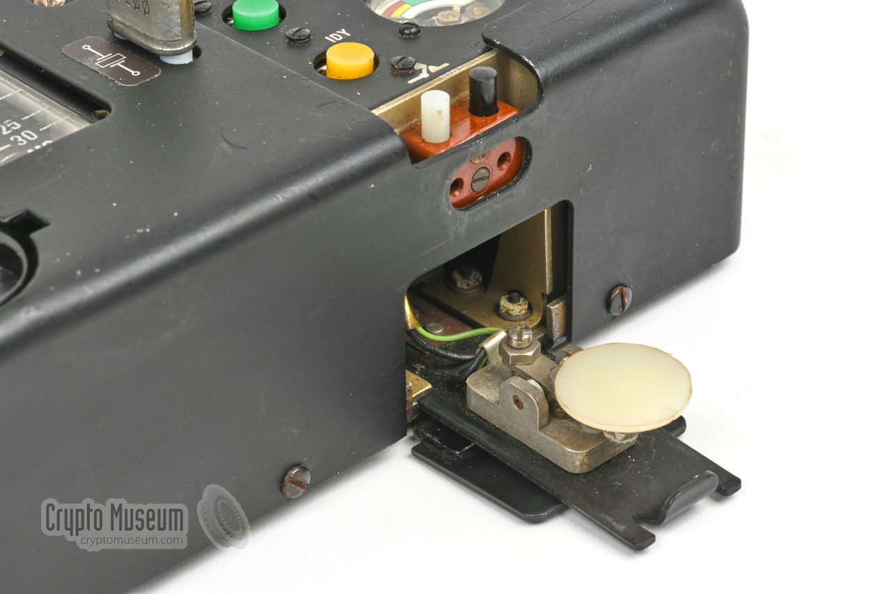
If necessary, the AT-3 can also be used for bare manual
transmissions, by using the extractable morse key,
or connecting a larger external one.
|
|
|
Being a development from the late 1950s, the transmitter is a so-called hybrid,
which means that it is partly built with transistors and partly with valves
(tubes). In fact, there are just two valves — one for the exciter and one
for the power amplifier (PA). All other circuits are transistor-based.
Development of the set started in 1956, and took approx. four years.
The CIA introduced it in 1960. Two years later, in March 1962,
the AT-3 was evaluated by the US Army, but was found inadequate, and
the Army did not recognise the benefit of using a
burst encoder [4].
I is known that the AT-3 was used by European
stay-behind organisations,
such as the Belgian SDRA-8.
The unit featured here was probably manufactured in 1961,
as the valves have the date codes of weeks 39 and 42 of 1960
respectively. A self-adhesive label below the AT-3 name tag, shows
that a modification was carried out
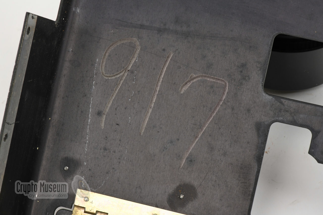
on 1 December 1962. The serial number
of this unit is 917, which is
imprinted at the bottom, and
written inside the case shell.
It is known that 10 prototypes were made in late 1960, followed
by a production run of 250 units in late 1960 or early 1961 [5].
|
 |
-
Full name: Hughes Aircraft Company.
After 1985 referred to as Hughes Electronics.
-
In CIA parlance: an agent radio set.
-
Batteries, crystal, receiver, printer and battery pack not included.
Internal morse key retracted.
|
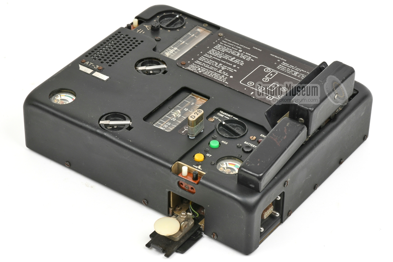
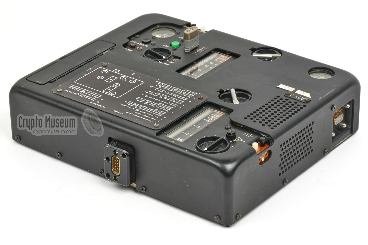
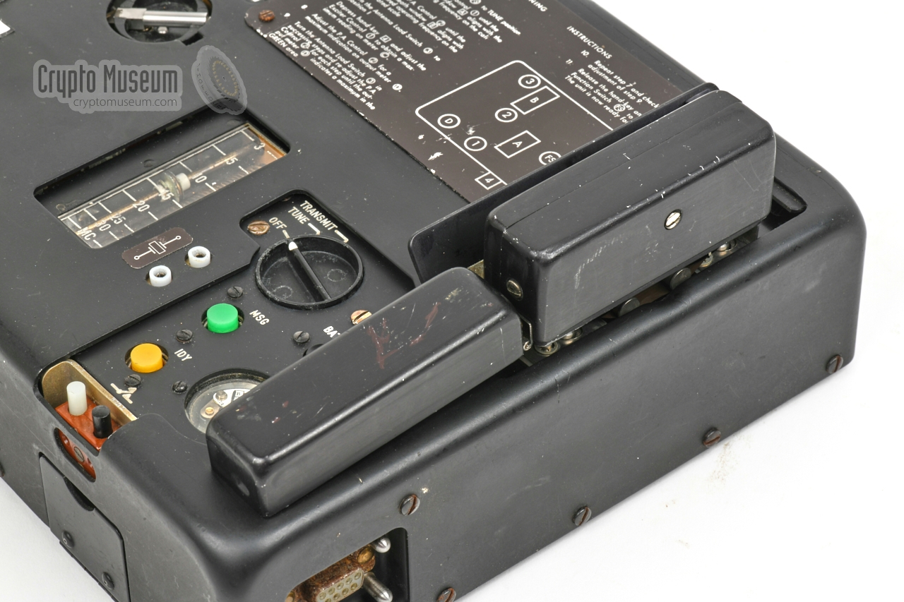
The diagram below gives an overview of the controls and connections of the
AT-3 transmitter. There are connections on all four sides: a 2-pin socket
for an external morse key at the front, a 2-pin antenna socket at the left and
a socket for connection of a 12V DC source at the rear.
Furthermore, there is a 9-pin female socket at the
right front
– for connection of an RR/E-11
or RR/D/11 receiver, and another one at the left front
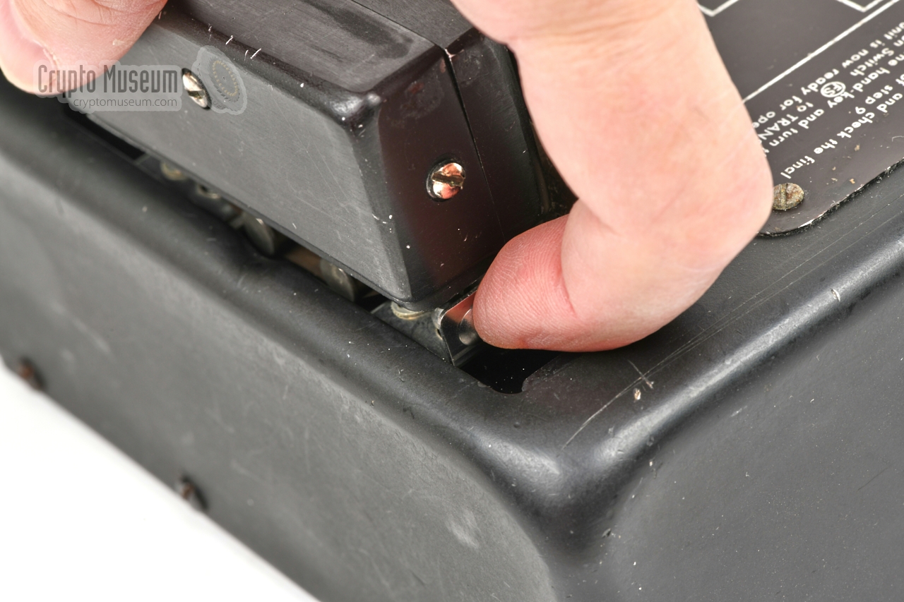
for connection of an optional HELL printer.
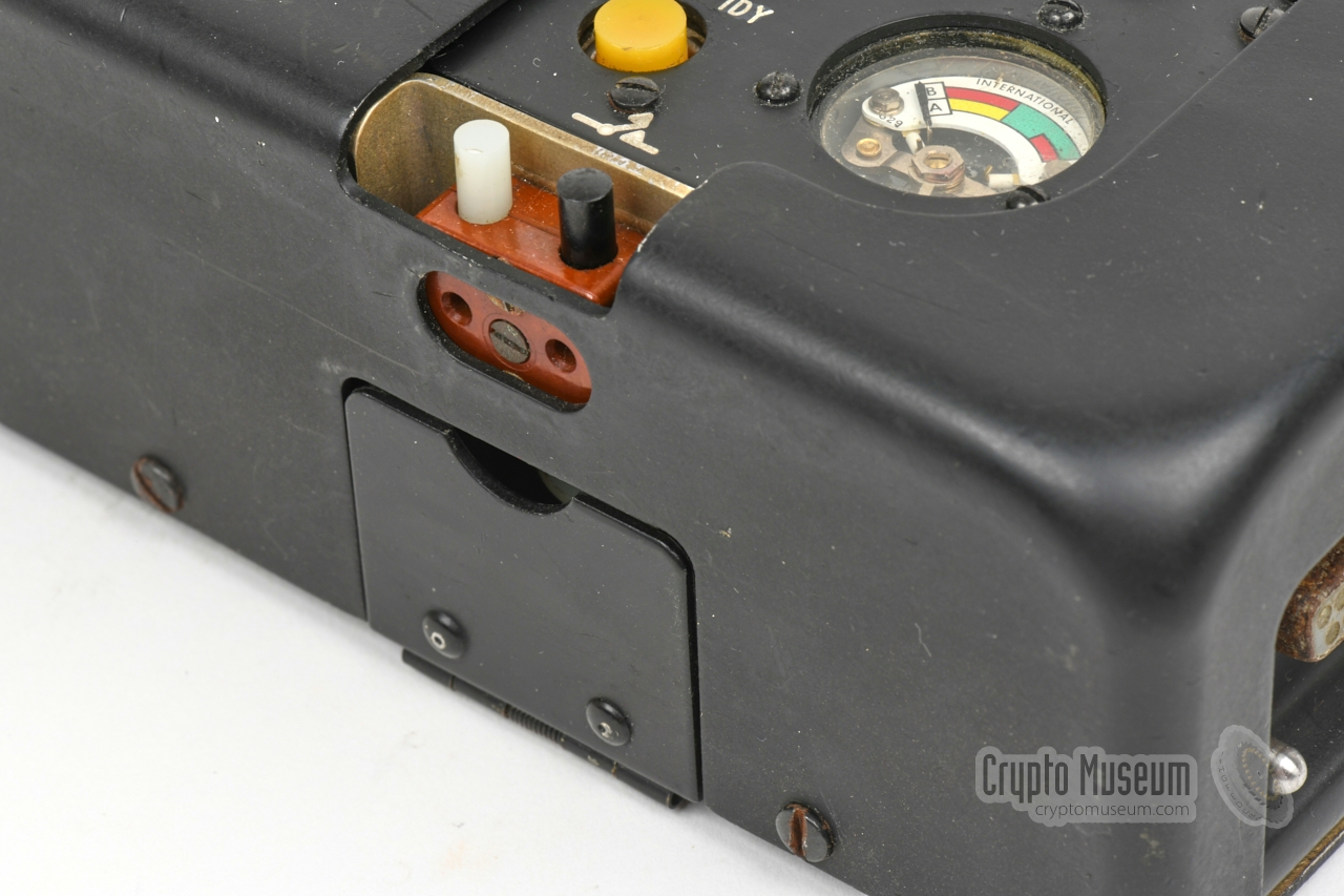
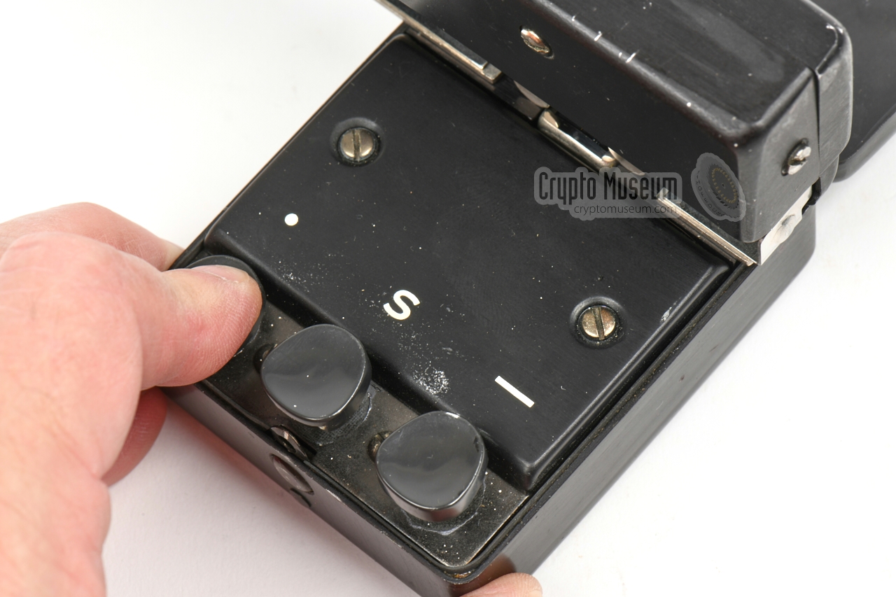
For emergency purposes, an internal morse key
is available behind a hinged lid at the front side.
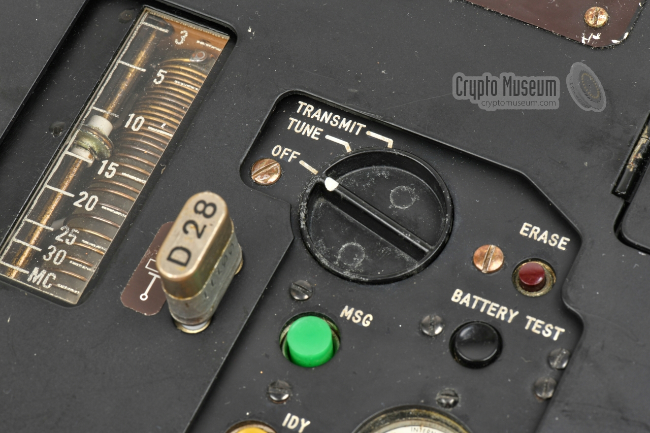
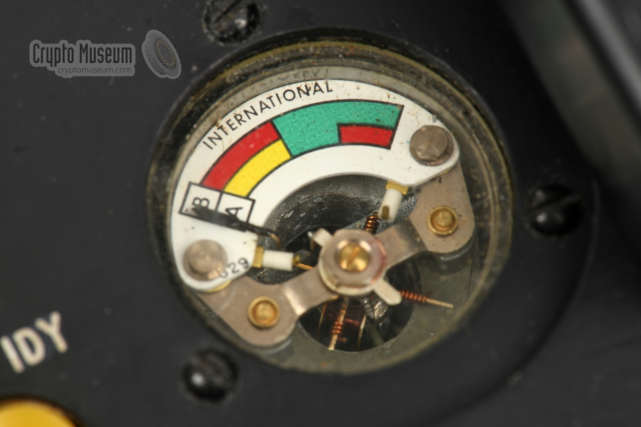
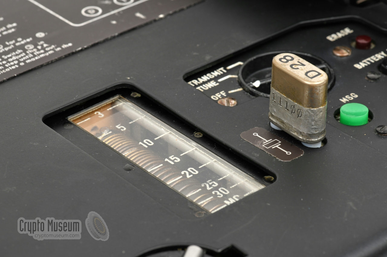
All controls are at the top surface. At the front right are the
MODE selector,
the voltage indicator and a socket for the crystal.
Towards the centre is the valve-based exciter, which should be tuned to the desired frequency. At the
left is the power amplifier (PA) stage, which is also valve-based.
The PA range selector and the PA tuning scale
should be adjusted for maximum power output.
At the right is the burst keyer, which consists of a motor-driven magnetic
tape reader. It has a bay
– hidden below a hinged lid –
that accepts a CA-3 tape cartridge. The image above shows the
AT-3 transmitter
with the CA-3 tape cartridge installed.
Once the transmitter has been tuned to the desired
(crystal) frequency, the MODE selector
is set to TRANSMIT and the
MSG-button is pressed to transmit the pre-recorded message at high speed
in morse code (burst transmission).
|
|
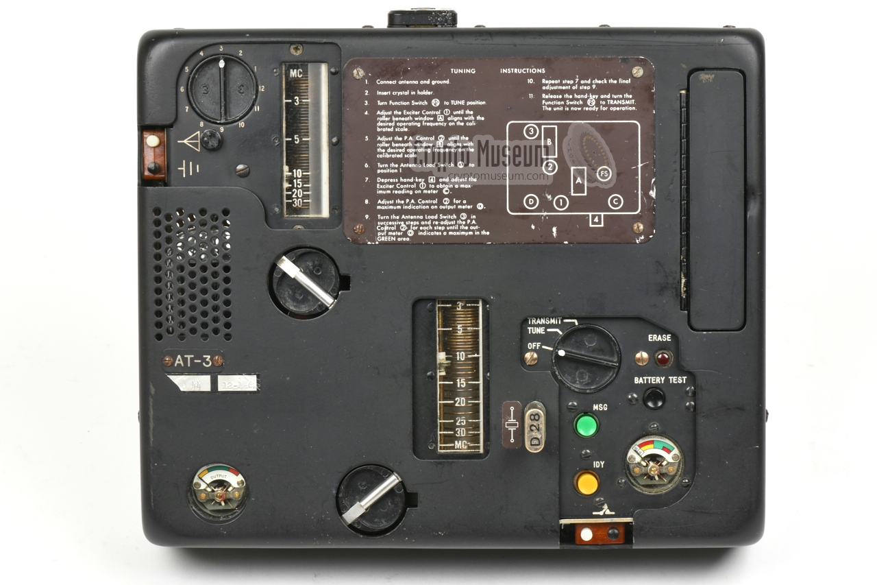
At the right half of the control panel is the main function switch, or
MODE selector.
It has three settings: OFF, TUNE and TRANSMIT. Note that
in the OFF position, the filaments of the valves are already powered,
so that the valves are pre-heated when the MODE selector is set to
TUNE or TRANSMIT. In this state the device consumes approx. 0.98A.
For this reason, the battery pack should be disconnected
when the device is not in use.
In the TUNE-state the current is 2.87A.
|
- Connect antenna and ground
- Connect battery pack or other 12V DC source
- Insert crystal in holder
- Set MODE selector to TUNE
- Set exciter tuning knob to desired frequency
- Set PA tuning knob to desired frequency
- Set antenna load selector to position 1
- Depress internal morse key
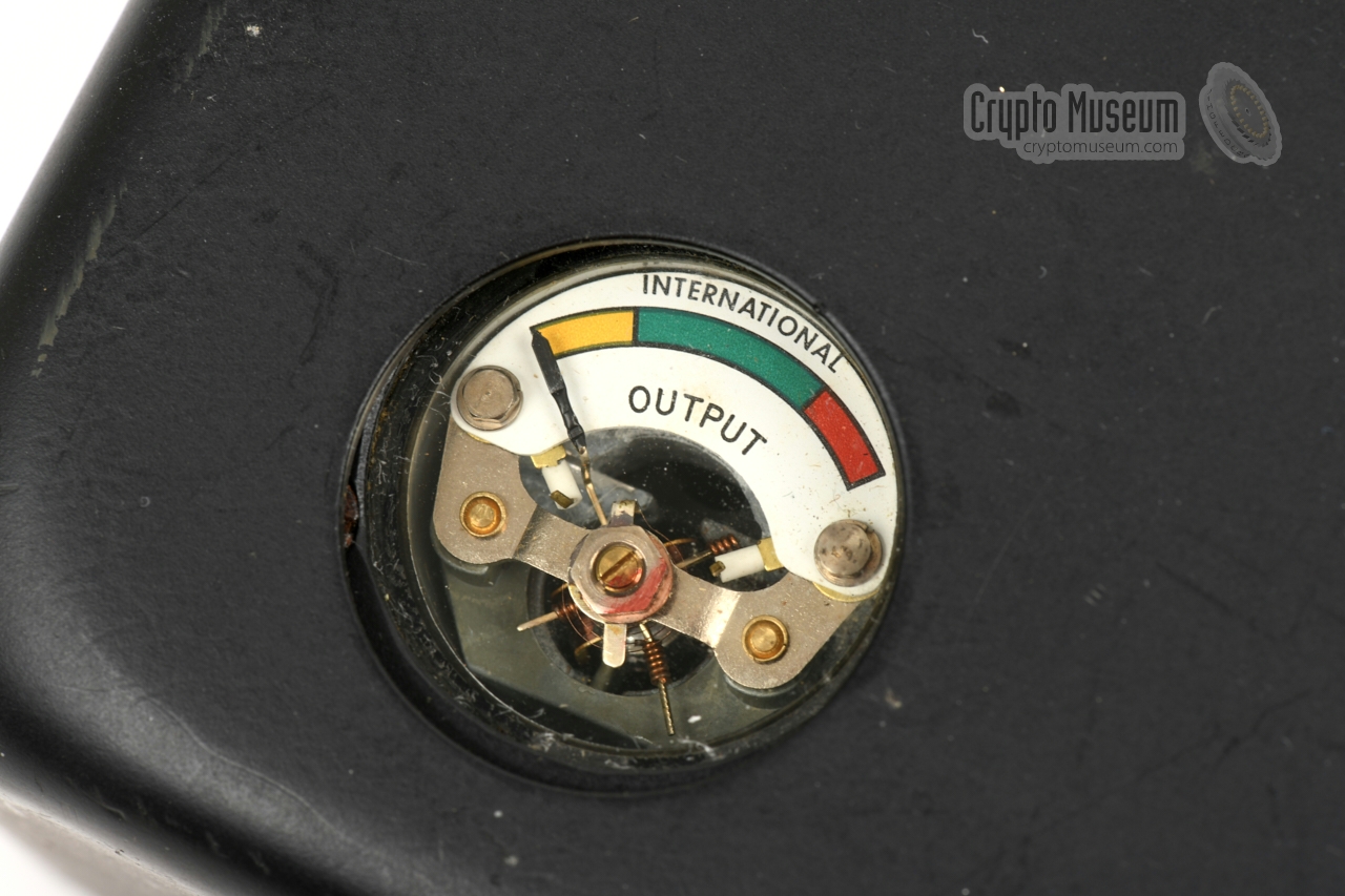
- Adjust exciter tuning knob for maximum reading on rightmost meter
- Adjust PA tuning knob for maximum reading on leftmost meter
- Try next setting of antenna load selector
- Repeat 9-10 until maximum is found
- Release internal morse key
- Set MODE selector to TRANSMIT
- Insert pre-recorded tape in cartridge bay
- Press MSG
- Once the message is transmitted, set MODE selector to OFF
- Disconnect battery or other 12V DC source
|
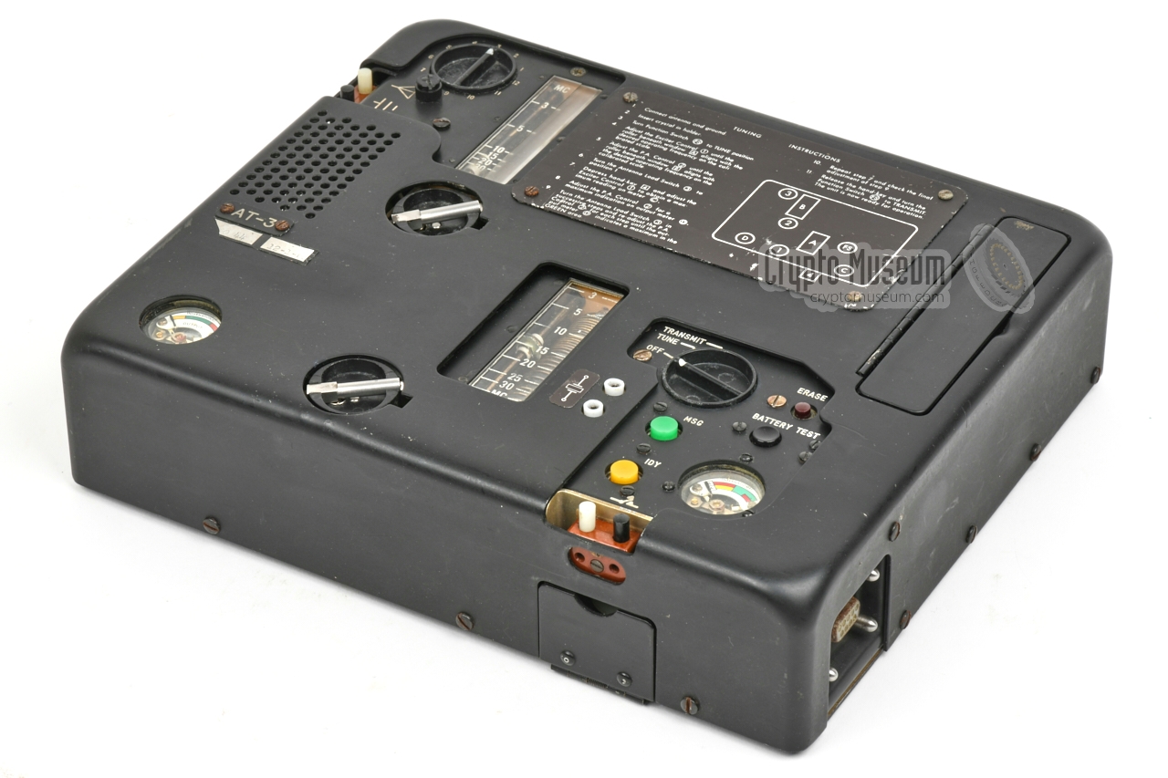
The AT-3 transmitter is the central piece of the AS-3 spy radio set.
When all accessories are removed, it looks like the image on the right. In this
state, the dimensions are 26 x 22 x 6 cm; small enough to fit it inside a
regular Samsonite briefcase of the era.
At the right side, it can be expanded with a single-
or double-band receiver.
At the left side it can be expanded with a printer. A battery pack or
AC/PSU should be connected at the rear.
|
|
|
The transmission frequency of the AT-3 is determined by a quartz crystal
that must be inserted into the crystal socket at the centre of the control
panel. The crystal frequency – in the range 3 to 30 MHz –
corresponds directly to the transmission frequency.
The sockets accepts HC-6U crystals with a pin distance of 12.5 mm and a pin
diameter of 2.5 mm. Examples of such crystals are shown in the image on the
right.
|
|
|
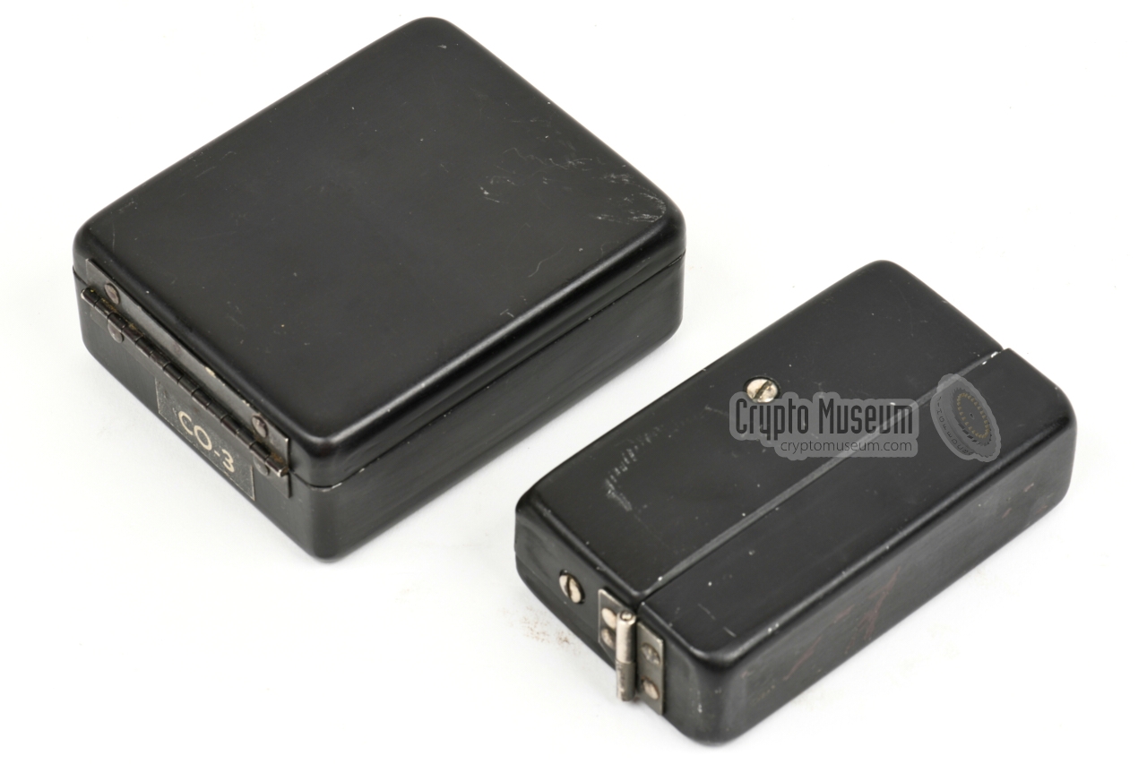
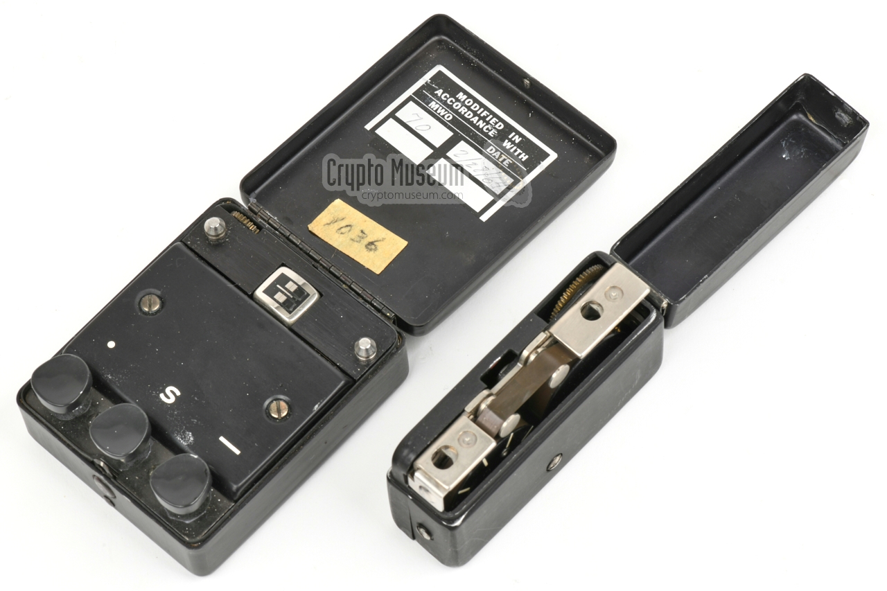
Messages – generally encrypted or otherwise coded –
were pre-recorded with the CO-3 coder
shown above, onto a CA-3 tape cartridge as shown in the image
on the right. The cartridge contains regular magnetic audio tape of the era,
and can hold up to 150 five-character words.
Recording a message was time-consuming, as each dot, dash and space had to be
entered separately. But once it was recorded, it could be sent in a
matter of seconds,
which significantly reduced the on-air time and hence the
risk of discovery by means of radio direction finding.
|
|
|
RR/E-11 was among the first solid-state spy receivers
developed by the CIA Radio Lab. It was intended for use as part
of the AS-3 radio set,
and could be plugged into the right side
of the AT-3 transmitter,
in which case power (12V) and antenna signal were supplied by the
transmitter.
The receiver, which was released well before the
AS-3 radio station was ready,
could also be used stand-alone, in which
case it could be powered by a 6V or 12V DC source, whilst antenna
and headphones were connected directly to the unit.
➤ More information
|
|
|
|
|
Two-band receiver
RR/D-11
|
|
|
RR/D-11 was a plug-in receiver for the AS-3 radio station, that was
similar to the RR/E-11 shown above, albeit with two frequency bands
instead of one. The receiver is approx. 2.5 cm (one inch) deeper than
the RR/E-11, but can be plugged into the
same socket of the transmitter.
In many respects, the RR/D-11 is similar to the
German FE-8 (BN-58) receiver
of the same era.
At present, no image of this item is available.
|
|
|
For portable and mobile operation, the AT-3 can be powered by a purpose-built
battery pack, designated BP-3, which is plugged into the
9-pin male receptacle
at the rear centre.
The BP-3 delivers a voltage of 12V DC at 10A.
At present, no image of this item is available.
|
|
|
|
|
AC power supply unit
AP-3
|
|
|
According to the original documentation, an external power supply unit (PSU)
was available for powering the transmitter directly from the mains (110 - 240V AC).
At present, no image of this item is available.
|
|
|
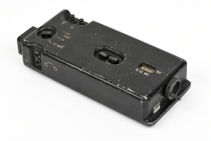
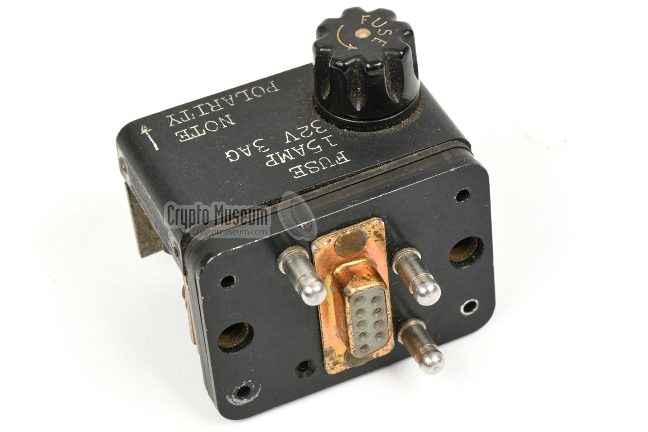
It was also possible to power the AT-3 directly from any other suitable
12V DV power source, such as the battery of a vehicle, by using the adapter
shown in the image on the right.
It plugs straight into the
receptacle
at the centre of the rear panel,
and has two screw terminals for
connection to the external 12V DC source.
It has a 15A fuse and an internal germanium power diode that blows
the fuse when the 12V DC source is connected the wrong way around.
The side panels are currently missing from this item.
|
|
|
The AT-3 was supplied with a comprehensive user's manual
that contains detailed operating instructions and well as a
technical descriptions of the various circuit,
with full circuit diagrams.
➤ Download the manual
➤ Circuit diagram only
|
|
|
|
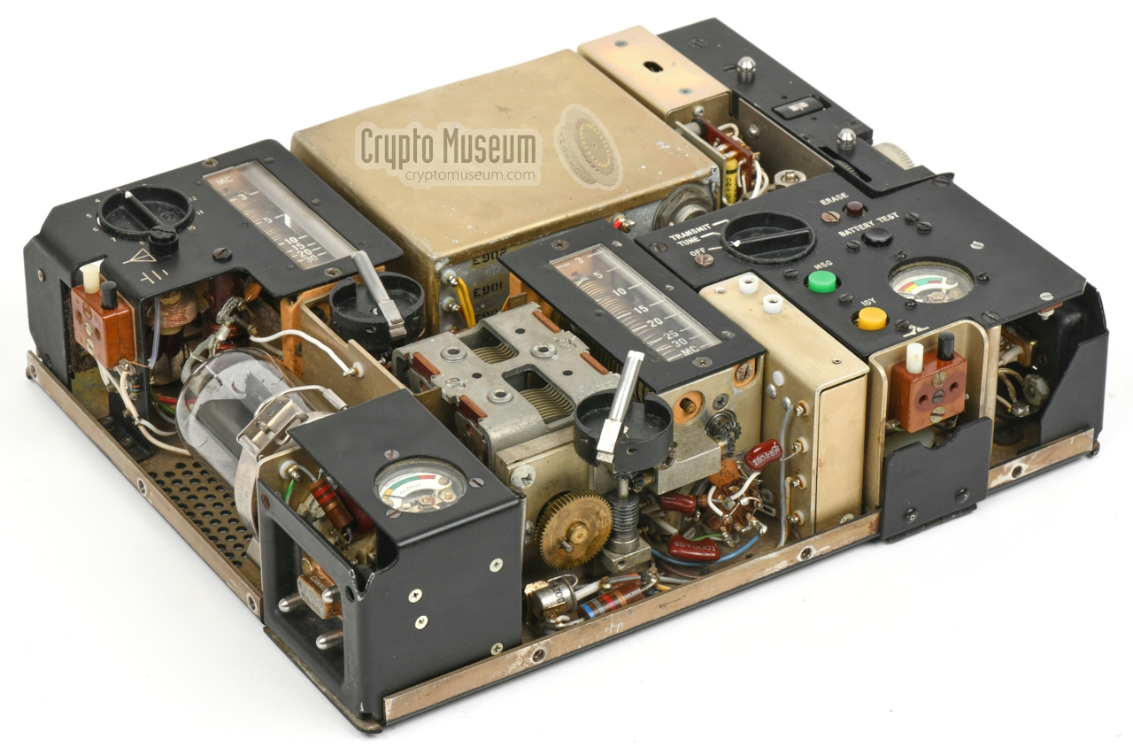
The AT-3 consists of a metal base plate onto which all parts and circuits
are mounted, covered by a somewhat rounded metal case shell. The case shell
is held in place by 17 screws, divided over the four sides, close to the bottom
edge. After removing these screws, the case shell comes off.
|
The interior, shown in the image on the right, consists of several tuning
mechanisms, circuits and sub-circuits, merged in a construction that is
typically American for the era. Considering its age, this particular unit
is very well preserved.
The transmitter is a typical hybrid, in the sense that transistors are used in the
oscillator and keyer circuits, whilst valves are used for the exciter
(pre-amplifier) and the power amplifier (PA). The 6883 PA valve is
accessible at the left side,
and is retained by a spring-loaded clip.
It has a removable anode connection at the top.
|
|
|
|
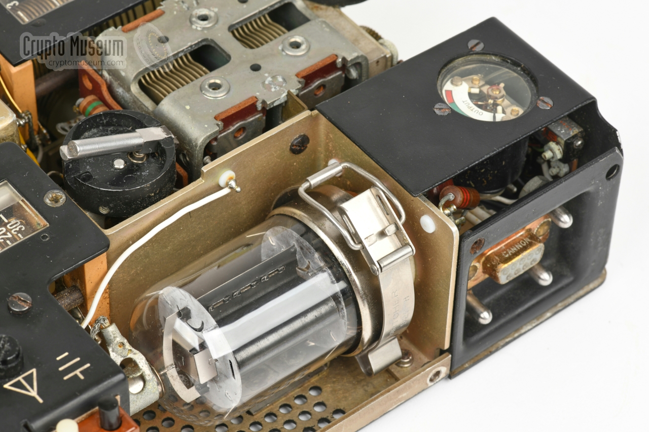
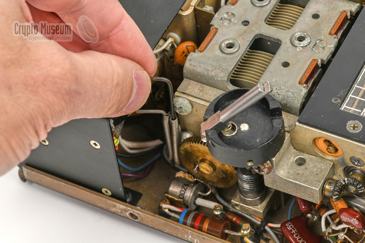
The 6883 is a compact yet high power valve that was used in audio amplifiers
as well as in the RF output stage of transmitters. It is capable of delivering
no less than 25 Watts to the antenna.
Removing it might require the gentle use of a screwdriver, as it is
firmly seated in its octal socket.
|
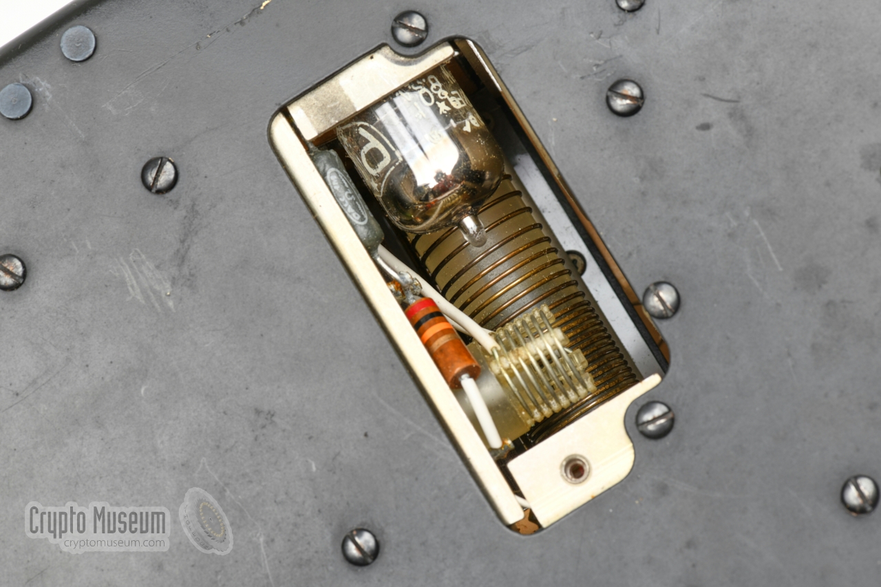
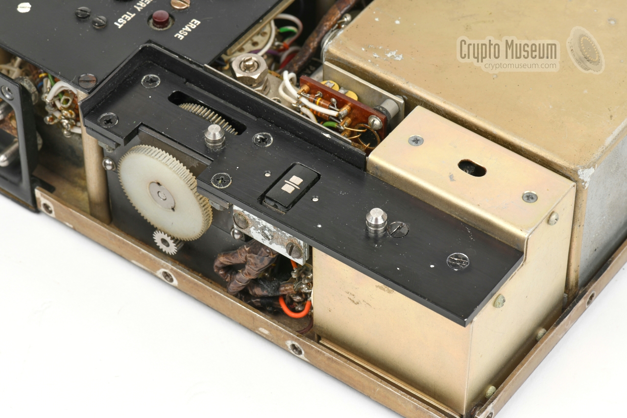
The exciter valve is a bit more difficult to reach, as it is deeply embedded
in the device. Luckily, it can be reached through a removable lid in the
bottom panel. The lid is held in place by a single
screw, and once it is removed, the
small 6688 valve
becomes (partly) visible
as shown in the image on the right. Also visible, below the valve, is the
exciter's unevenly spaced tuning coil.
In order to withstand severe transport shocks, the designers have chosen
to use the Premium Quality (PQ) 1 variant of
the valve in this case. It is extra strong and has gold-plated contacts.
|
|
|
|
Despite the fact that the 6688 valve is accessible through the lid,
removing it can be tricky, as there is no space to hold it. This can be
solved by using a push-tool that is inserted through the hole at the
centre of the valve's socket, which can be reached
from the front of the device.
|
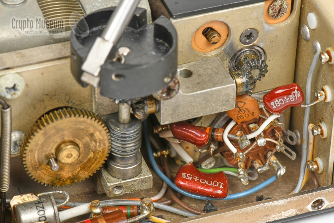
The remaining circuits are very difficult to access and may require the
transmitter to be partly disassembled. Most of the sub-circuits are
bolted to the bottom panel and can be loosened by removing the
relevent screws from the bottom. In some cases it may be necessary to
remove one or more of the tuning knobs, for which
two small hex wrenches are stowed inside the device.
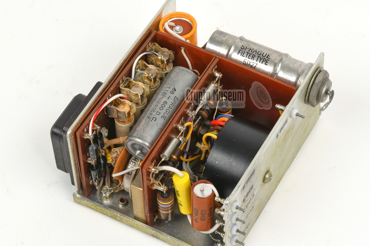
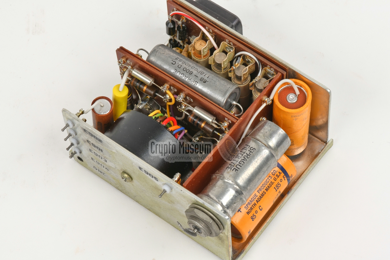
The largest sub-circuit is the internal power supply unit, which is
located at the rear centre. It holds the
9-pin male receptacle to which
the battery or external PSU should be connected.
|
|
|
|
It converts the 12V DC source supply into -70V, +215V and +450V for the
valve-based circuits. The filaments of the valves and the transistor-based
circuits are powered directly by 12V.
Note that the -70V voltage is also used for the (transistor-based) keyer.
The image above shows the power converter with its
upper case shell removed. At the right is the black toroidal transformer.
|
-
Equivalent to the Philips designation Special Quality (SQ).
|
When we obtained the transmitter featured on this page, it was in
reasonable condition, albeit dusty and dirty. Apparently it had been
stored in a damp place for several years, as corrosion was found on the
screws, the tuning coils and at the places were two different types of
metal are in contact with each other. However, treating the corroded
parts and applying a drop of oil and grease to the movable parts,
appeared to be enough to make the device fully operational again.
So far, the following work has been done on our AT-3:
|
- Exterior cleaned
- All exterior screws derusted
- Receiver socket derusted
- Dymo label residue removed from front panel
- Oscillator coil cleaned
- PA coil cleaned
- All moving parts oiled and greased
|
|
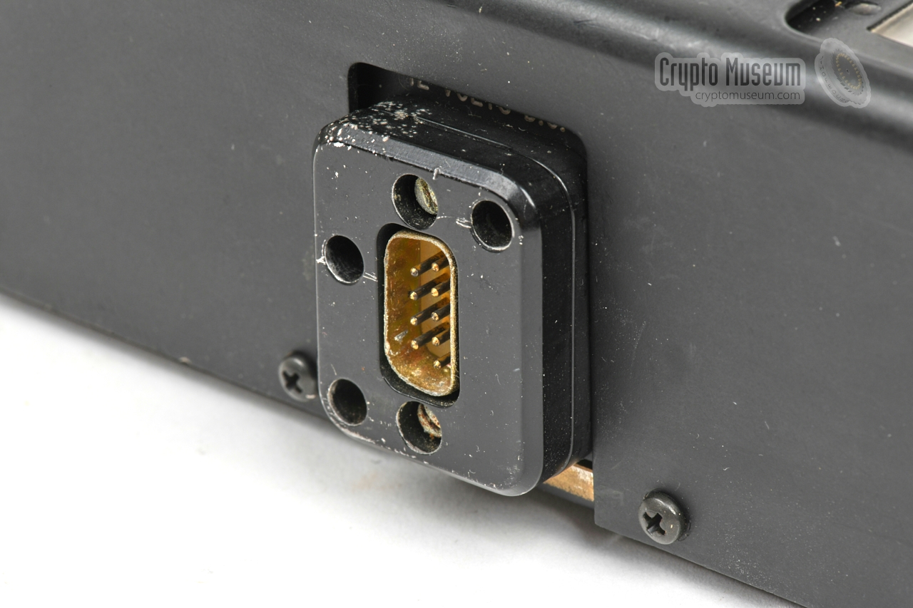
The AT-3 is powered by a 12V DC source, which should be connected to the 9-pin
male socket (DE9/M) at the rear. Although this socket has 9-pins, the pins of each row
are interconnected, in order to withstand high currents. The socket is suitable for
connection of a BA-3 battery pack, an AC power supply unit, or a 12V terminal adapter.
The latter contains a fuse holder (with a 15A fuse) and a heavy germanium diode that
blows the fuse when the polarity is accidentally reversed.
|
- +12V
- +12V
- +12V
- +12V
- +12V
- 0V
- 0V
- 0V
- 0V
|
|
|
|
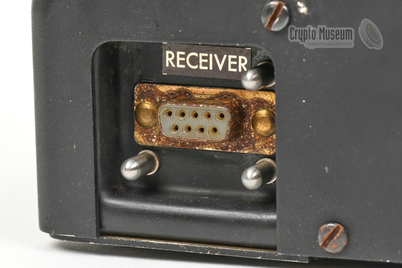
Receiver interface
DE-9/F
|
|
|
|
At the right side of the transmitter, close towards the front, is a
9-pin DE-9/F socket for connection to an (optional) receiver.
The socket is suitable for connection of the RR/E-11 and the
RR/D-11 receiver.
|
- Antenna
- Ground
- n.c.
- n.c.
- Jumper to 6 when used with 12V DC
- +6V DC input
- n.c.
- +12V DC input
- Audio output
|
|
|
|
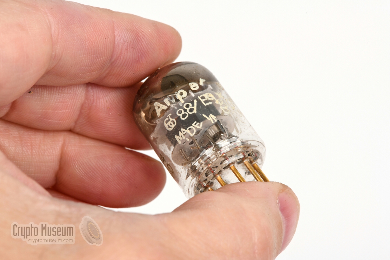
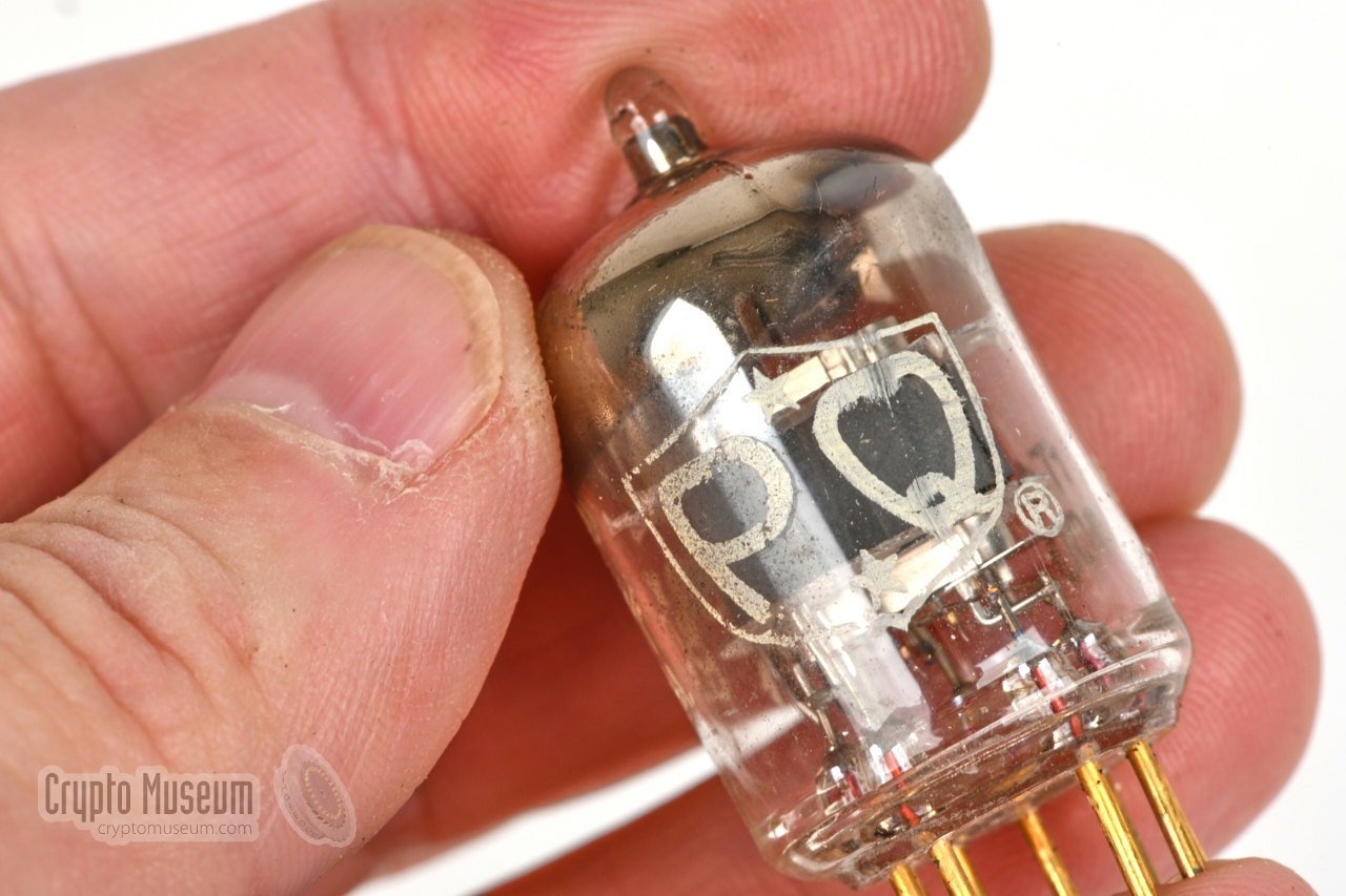
Exciter valve · PQ 6688/E
|
|
|
An Amperex 6688 valve (tube) is used in the exciter of the AT-3 transmitter.
It is a low-profile penthode valve with 9 gold-plated contact pins, as
indicated by the PQ marking on the exterior. The valve is equivalent to the
Tesla E180F and to the 6J9P.
➤ 6688 datasheet
|
Device Spy radio transmitter with burst transmitter Purpose Agent communication Year 1960 Developer Hughes Aircraft Company (California, USA) Customers CIA, Stay-Behind Organisations, SDRA-8 Frequency 3 - 30 MHz Output 25W Crystals FT-243 or CR-58/U Supply 12V DC / 10A Duty cycle Continuous Cartridge CA-3 (150 five-letter groups) Valves 6688, 6883 Dimensions 260 × 220 × 60 mm Weight 3.5 kg
|
|
The following items are currently missing from our AT-3:
|
- BP-3 battery pack
- AP-3 AC adapter
- TP-3 printer
- RR/D-11 receiver
|
917 Crypto Museum (Netherlands)
|
|
The model number of the unit is engraved in a small black tag that is located
near the left edge of the top surface, just below the ventilation holes of the
PA valve. It is held in place by two screws, so that it could be swapped if
the Army adopted it as well. The serial number is
imprinted at the bottom of the case,
near the ventilation holes of the PA valve. It is also
written inside the upper case shell.
It is estimated that at least 260 units were made.
|
|
If you own an AT-3 transmitter with a serial number that is not listed here,
please let us know, as it may help us to make an educated guess of the actual
quantity that was produced.
➤ Contact us
|
- Development of AS-3 Portable Radio Station, Progress Report No. 1
1 October 1956. 1
- Development of AS-3 Portable Radio Station, Progress Report No. 2
1 November 1956. 1
- Development of the Semi-Automatic Two-Way Radio Station AS-3, Progress Report No. 3
1 January 1957. 1
- Development of the Semi-Automatic Two-Way Radio Station AS-3, Progress Report No. 4
11 March 1957. 1
- Development of the Semi-Automatic Two-Way Radio Station AS-3, Progress Report No. 5
1 May 1957. 1
- Development of the Semi-Automatic Two-Way Radio Station AS-3, Progress Report No. 6
1 July 1957. 1
- Development of the Semi-Automatic Two-Way Radio Station AS-3, Progress Report No. 8
1 November 1957. 1
- Contract RD-122, Task Order 1 - AS-3
15 November 1956. 1
- Contract RD-122, Task Order 1 - AS-3
18 December 1956. 1
- Contract RD-122, Task Order 1 - AS-3
7 February 1957. 1
- Contract RD-122, Task 1 - AS-3 - Trip Report
18 March 1957. 1
- AS-3 Contract RD-122 - Trip Report
10 May 1957. 1
- Trip Report - Discussions on RS-11 and AS-3 Equipment
10 May 1957. 1
- Trip Report - RD-122 - AS-3
24 June 1957. 1
- Trip Report - RD-122 - AS-3
18 December 1958. 1
- Trip Report - AS-3
17 April 1959. 1
- AS-3 Agent Communication System (Project 2108)
13 December 1956. 1
- Semi-Automatic Agent Communications Set, AS-3 (Project 2108)
30 July 1957. 1
- TP-3 Motors
19 November 1957. 1
- Preliminary Evaluation of TP-3, Hellschreiber Transistorized Printer
19 December 1957. 1
- Trip Report - AS-3 Tests (hints to Hellschreiber usage)
23 April 1959. 1
- Development of a Minature DC Motor for the TP-3 printer
30 December 1959. 1
- Technical Notes on AT-3 Transmitter
26 August 1960. 1
- Army Evaluation of AS-3 Equipment
5 March 1962. 1
- Defects in AS-3 Prototype - Attachment 'A'
Date unknown.
- Suggested AS-3 Accessories
8 May 1959. 1
- Conference Report, Radio Station AS-3
19 July 1957. 1
- Conference Report, Radio Station AS-3
27 May 1957. 1
- Conference Report, AS-3
31 October 1958. 1
|
-
Sanitized copy approved for release by CIA on 14 February 2013 — 2 April 2013.
|
-
Sanitized copy approved for release by CIA on 14 February 2013 — 2 April 2013.
|
|
|
|
Any links shown in red are currently unavailable.
If you like the information on this website, why not make a donation?
© Crypto Museum. Created: Monday 31 August 2020. Last changed: Wednesday, 05 November 2025 - 12:05 CET.
|
|

|
|
|