|
|
|
|
|

|
|
USA CIA RR/E-11 → AT-3 →
-
AS = Automatic Station
(as opposed to RS = Radio Station).
|
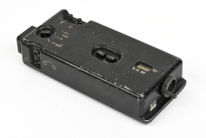
The AT-3 transmitter is the central piece of the AS-3 spy radio set.
It measures 26 x 22 x 6 cm and weighs approx. 3.5 kg. It is powered
by a 12DC source (10A), and produces 25W output.
At the top right is a hinged lid below which is a bay for a
CA-3 tape cartridge. It allows a pre-recorded message
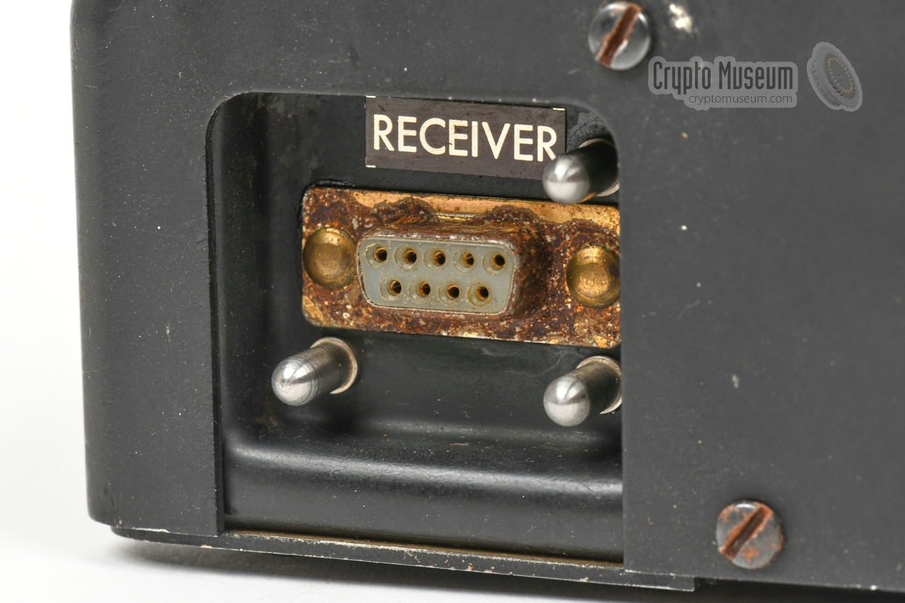
to be played back at 300 words per minute. At the right side is a socket
for the RR/E-11 or RR/D-11 receiver.
At the left is a socket for a TP-3 HELL printer.
➤ More information
|
|
|
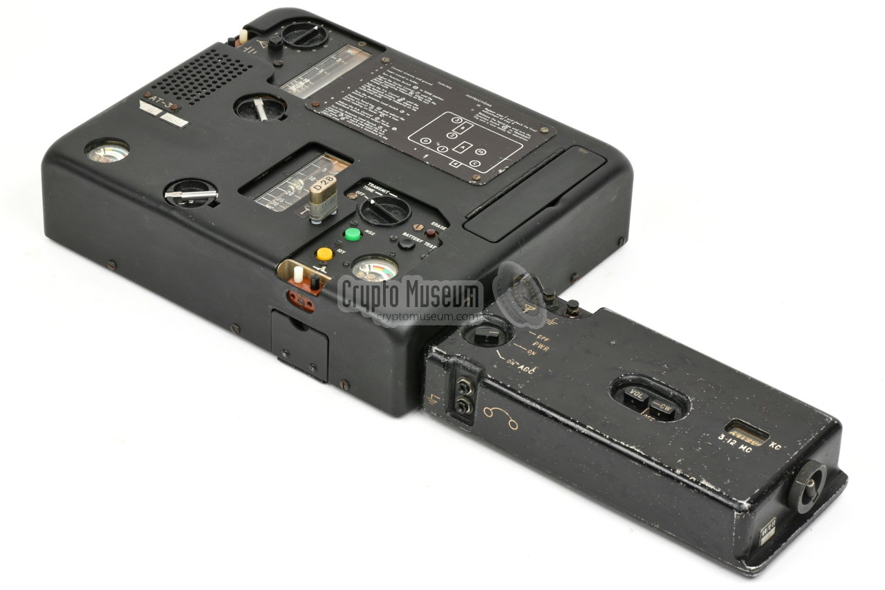
RR/E-11 was among the first solid-state spy receivers developed
by the CIA Radio Lab. It was intended for use as part of the AS-3 radio
set, and could be plugged
into the right side of the AT-3 transmitter,
in which case power (12V) and antenna signal were supplied by the
transmitter.
The receiver, which was released well before the AS-3 radio station was
ready, could also be used stand-alone, in which
case it could be powered by a 6V or 12V DC source, whilst antenna
and headphones were connected directly to the unit.
➤ More information
|
|
|
|
|
Two-band receiver
RR/D-11
|
|
|
RR/D-11 was a plug-in receiver for the AS-3 radio station, that was
similar to the RR/E-11 shown above, albeit with two frequency bands
instead of one. The receiver is approx. 2.5 cm (one inch) deeper than
the RR/E-11, but can be plugged into the
same socket of the transmitter.
At present, no image of the two-band RR/D-11 receiver is available.
|
|
|
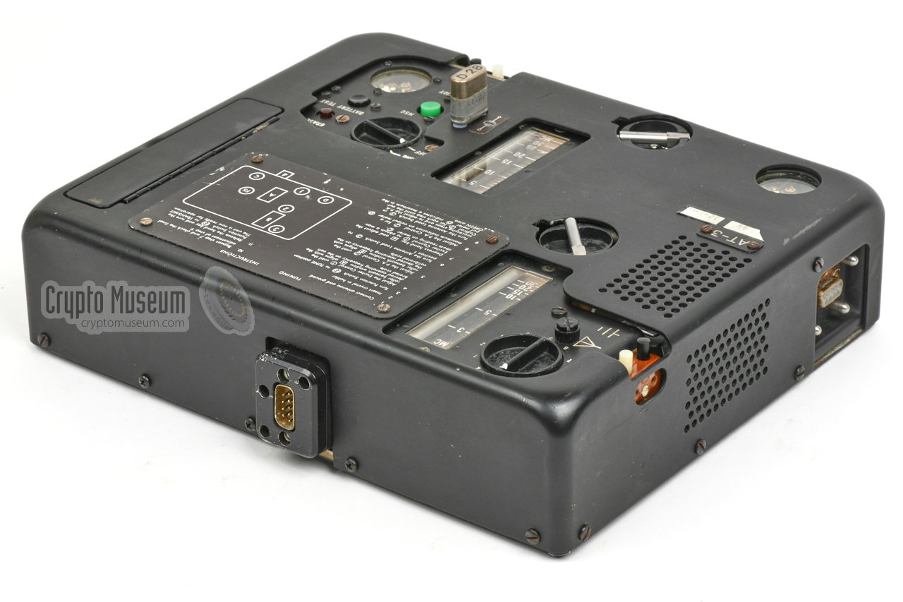
For portable and mobile operation, the AT-3 could be powered by a purpose-built
battery pack, designated BP-3, which plugged into the
9-pin male receptacle
at the rear centre.
It delivered a voltage of 12V DC at 10A.
At present, no image of the original BP-3 battery pack is available, but
it is likely that it had the same width and hight as the transmitter. The depth
is currently unknown.
|
|
|
|
|
AC power supply unit
AP-3
|
|
|
According to the original documentation, an external power supply unit (PSU)
was available for powering the transmitter directly from the mains (110 - 240V AC).
At present, no image of the AP-3 power supply unit is available.
|
|
|
TP-3 was a tape printer that could be inserted into the left side of
the AT-3 transmitter. It allowed Hellschreiber signals from the RR/E-11
or RR/D-11 receiver (connected at the right side of the transmitter) to
be printed on a paper strip.
It is currently unknown what the TP-3 printer looked like, and it is
uncertain whether there are any surviving pictures of it. If you have additional
information, please let us know.
➤ More information
|
|
|
The AS-3 radio set was probably the second US spy radio set to
use high-speed morse burst transmissions to reduce the chance of
detection and discovery by radio direction finding (RDF).
The first one was the RS-1 which it replaced.
The CO-3 was a simple device that allowed the bare morse elements
– dots and dashes – to be recorded onto a CA-3 tape cartridge.
Once recorded, the tape was played back on the built-in keyer
of the AT-3 transmitter.
➤ More information
|
|
|
Messages – generally encrypted or otherwise coded –
were pre-recorded with the CO-3 coder
shown above, onto a CA-3 tape cartridge as shown in the image
on the right. The cartridge contains regular magnetic audio tape of the era,
and can hold up to 150 five-character words.
Recording a message was time-consuming, as each dot, dash and space had to be
entered separately. But once it was recorded, it could be sent in a
matter of seconds,
which significantly reduced the chance of discovery by means of
radio direction finding (RDF).
|
|
|
Development of the AS-3 started in 1956 and was finished in 1959 or 1960.
A total of 150 receivers (RR/D-11 and RR/E-11)
were procured for delivery
in May 1959, and the final report was delivered in July 1959.
Production of the AT-3 transmitter was halted however,
but in August 1960, 10 prototypes were
available, with an anticipated production run of 250 units [w].
|
Frequency 3 - 30 MHz Output 25W Supply 12V DC / 10A Dimensions 26 × 22 × 6 cm Weight 3.5 kg
|
Bands 1 Frequency 3 - 12 MHz Dimensions 22 × 11 × 4 cm Weight 1.9 kg
|
Bands 2 Frequency 3 - 12 MHz & 12 - 30 MHz Dimensions 22 × 13.5 × 4 cm Weight 1.9 kg
|
- Development of AS-3 Portable Radio Station, Progress Report No. 1
1 October 1956. 1
- Development of AS-3 Portable Radio Station, Progress Report No. 2
1 November 1956. 1
- Development of the Semi-Automatic Two-Way Radio Station AS-3, Progress Report No. 3
1 January 1957. 1
- Development of the Semi-Automatic Two-Way Radio Station AS-3, Progress Report No. 4
11 March 1957. 1
- Development of the Semi-Automatic Two-Way Radio Station AS-3, Progress Report No. 5
1 May 1957. 1
- Development of the Semi-Automatic Two-Way Radio Station AS-3, Progress Report No. 6
1 July 1957. 1
- Development of the Semi-Automatic Two-Way Radio Station AS-3, Progress Report No. 8
1 November 1957. 1
- Contract RD-122, Task Order 1 - AS-3
15 November 1956. 1
- Contract RD-122, Task Order 1 - AS-3
18 December 1956. 1
- Contract RD-122, Task Order 1 - AS-3
7 February 1957. 1
- Contract RD-122, Task 1 - AS-3 - Trip Report
18 March 1957. 1
- AS-3 Contract RD-122 - Trip Report
10 May 1957. 1
- Trip Report - Discussions on RS-11 and AS-3 Equipment
10 May 1957. 1
- Trip Report - RD-122 - AS-3
24 June 1957. 1
- Trip Report - RD-122 - AS-3
18 December 1958. 1
- Trip Report - AS-3
17 April 1959. 1
- AS-3 Agent Communication System (Project 2108)
13 December 1956. 1
- Semi-Automatic Agent Communications Set, AS-3 (Project 2108)
30 July 1957. 1
- TP-3 Motors
19 November 1957. 1
- Preliminary Evaluation of TP-3, Hellschreiber Transistorized Printer
19 December 1957. 1
- Trip Report - AS-3 Tests (hints to Hellschreiber usage)
23 April 1959. 1
- Development of a Minature DC Motor for the TP-3 printer
30 December 1959. 1
- Technical Notes on AT-3 Transmitter
26 August 1960. 1
- Army Evaluation of AS-3 Equipment
5 March 1962. 1
- Defects in AS-3 Prototype - Attachment 'A'
Date unknown.
- Suggested AS-3 Accessories
8 May 1959. 1
- Conference Report, Radio Station AS-3
19 July 1957. 1
- Conference Report, Radio Station AS-3
27 May 1957. 1
- Conference Report, AS-3
31 October 1958. 1
|
 |
-
Sanitized copy approved for release by CIA on 14 February 2013 — 2 April 2013.
|
|
|
|
Any links shown in red are currently unavailable.
If you like the information on this website, why not make a donation?
© Crypto Museum. Created: Monday 29 June 2020. Last changed: Wednesday, 05 November 2025 - 12:05 CET.
|
|

|
|
|


![Original AT-3 transmitter. Source unknown. Photograph obtained via Louis Meulstee [3].](img/303434/036/small.jpg)


