|
|
|
|
|

|
|
Radio HSA Thales MED →
The radio has a simple and clear control panel
with 15 rubber push-buttons,
a rotary selector, a large display and sockets for handset, data and antenna.
Up to 9 frequencies can be stored as presets.
A power socket is available at the right.
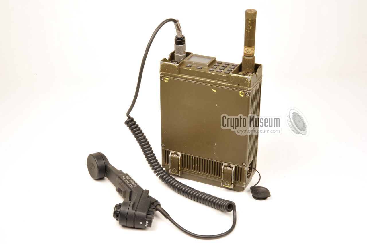
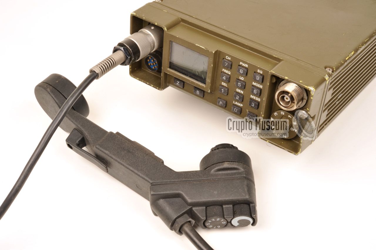
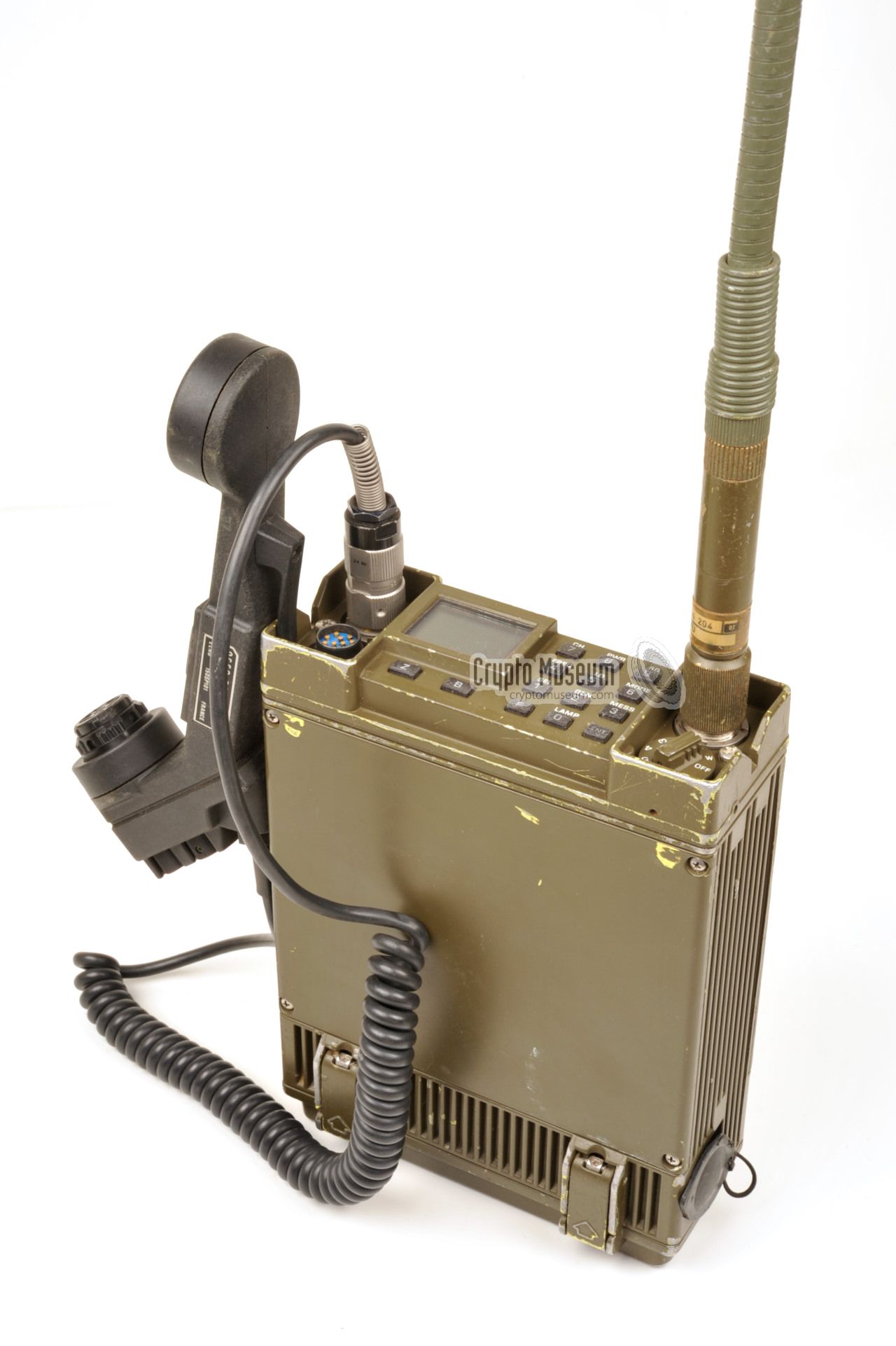
The image on the right shows the manpack version of the
radio set, with an
enhanced handset with remote capabilities.
The antenna is not shown here.
The unit measures 2 x 17.5 x 6.5 cm and weighs just 2.6 kg.
The complete manpack, including the batteries,
the handset, the antenna
and accessories weighs ± 5 kg.
|
|
|
The radio can be extended with an (optional) cypto unit,
which is mounted at the bottom.
This requires a 'bulged' bottom lid to be used instead of the normal one, in
order to accomodate an extra PCB which is fitted on top of the control board.
When the crypto unit is present, it provides full voice encryption and
decryption capabilities, as well as transmission of data at a variety of
speeds. In addition, the crypto unit supports burst transmission of up
to 99 pre-coded messages.
The transmitter output power has three levels (20mW, 200mW and 2W), plus
a 5W booster (B).
SPIDER, or S.P.I.D.E.R., is an acronym for Signaal Portable Infantry Digital
Encrypted Radio [1]. The radio was produced in small quantities especially for the Dutch
Special Forces (SF) and was mainly used abroad for short-range communication,
complementary to the existing long-range
LAPR (SE-6861) HF radio sets.
Although the radio is intended as a manpack
transceiver, it can also be
converted into a vehicular radio set by adding an
external power supply unit (PSU).
When used as a manpack, it can be used with dry cells as well as
with a rechargeable battery block.
|
 |
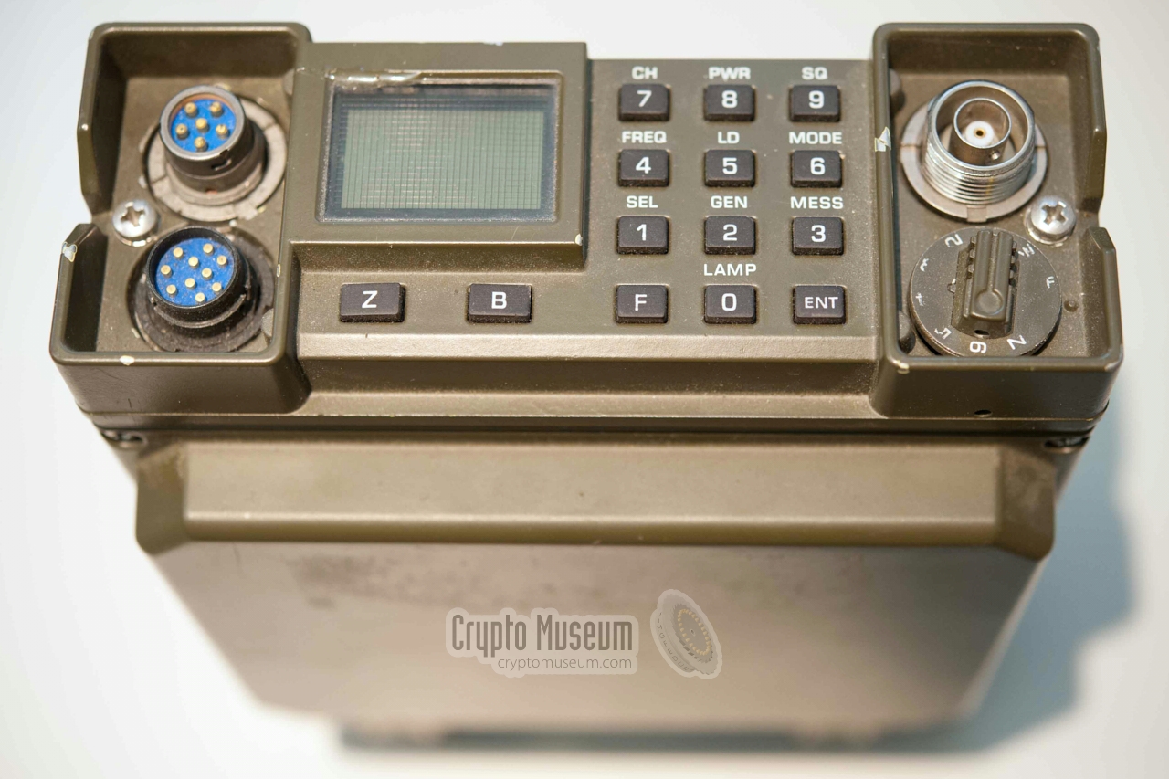
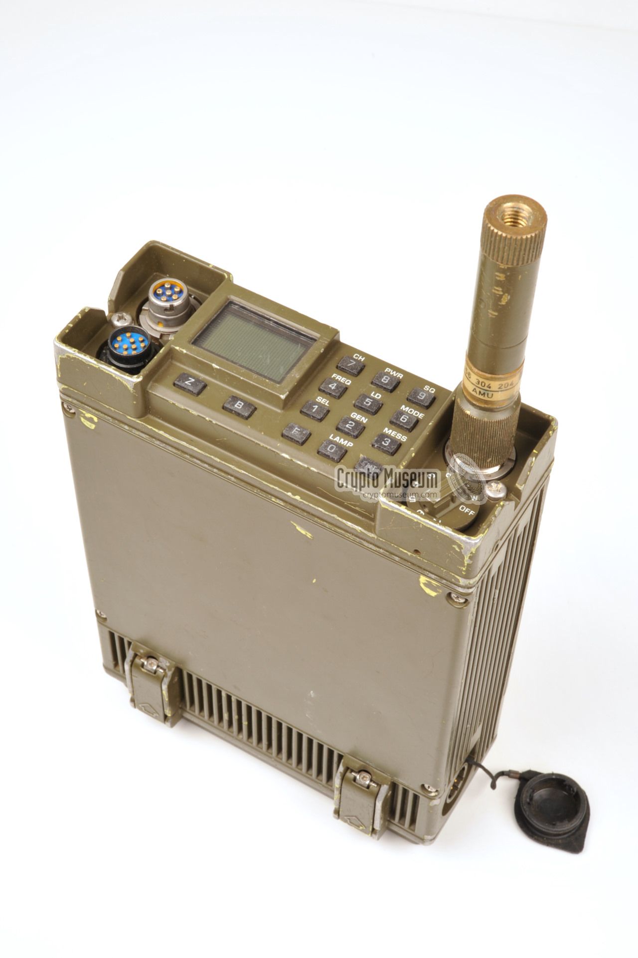
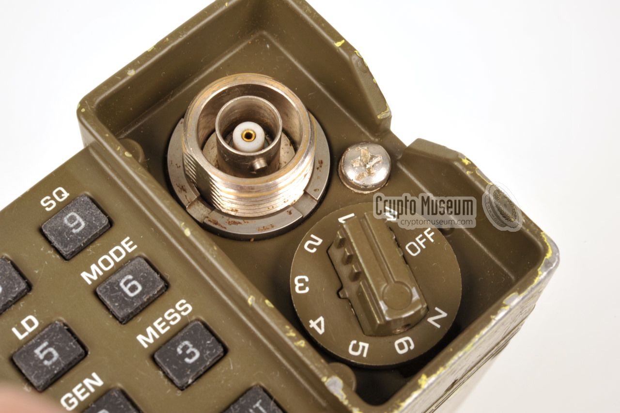
All controls and connections, with the exception of the
power socket,
are located at the control panel
at the front of the radio. In the diagram
below, the radio is placed vertically with its control panel at the top.
When used in manpack configuration, the radio is positioned this way.
At the left are two audio sockets,
one for a common US/NATO-standard handset
with a 5 or 6-pin U-229 connector,
and a 10-pin one that is suitable for
both audio and data. 1 At the right is a
50Ω BNC socket with a
threaded ring for connecting a rod-antenna 2 or an external
vehicle/base antenna.
At the bottom right is a 9-position rotary selector
that is used as ON/OFF switch and volume control.
The audio volume can be adjusted in
6 steps 3 with an extra Whisper Mode (W) before step 1. The last step of
the rotary switch is momentary and is marked (Z). If the switch is held in
this position and the Z-button on the keypad is pressed simultaneously,
the radio is zeroized. 1
All other functions
are controlled from the 12-button rubber keypad at
the center of the control panel, in combination with the clear LCD
display. It allows quick selection of a preset channel, programming of
the frequencies, adjustment of the RF output power and control of the
squelch. The display can also be illuminated. For a full description
of the functions look under operation.
|
|
|
The SPIDER can be powered in the following manners:
|
- Dry batteries
The radio can be powered by a replaceable battery pack that contains
dry Alkaline cells. These battery packs should not be recharged.
- Rechargeable batteries
Alternatively, the radio can be powered by a rechargeable battery
pack that contains 10 type R14 NiCd cells. In this case the batteries
can be recharged by supplying a current (100mA max.) to pin C of the
supply socket.
- External power supply unit (PSU)
In addition, the SPIDER can also be powered by an (optional) external
power supply unit (PSU) which should be connected to the
10-pin supply socket at the right rear.
It should supply 10-15V DC with a maximimum current of 2A.
A suitable PSU is available for connecting the radio to the 24V of
a vehicle when using it in a mobile configuration.
|
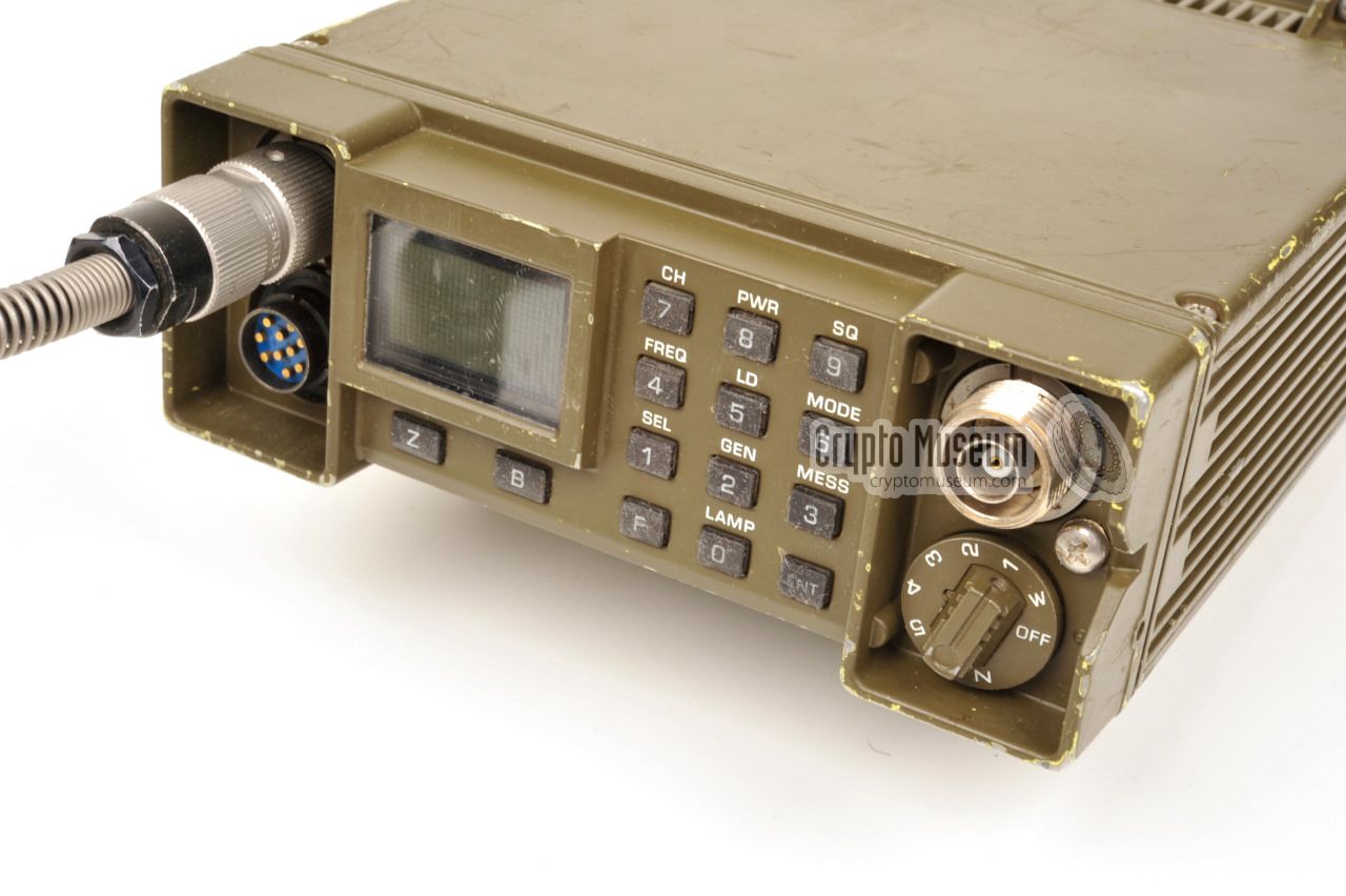
All features of the SPIDER, are accessible via the control panel
at the front (or top) of the radio.
The control panel consists of a clear and bright illuminated LCD display,
Zeroize (Z) and Booster (B) buttons, and a 12-button rubber keypad.
The buttons of the keypad are marked with the numbers (0-9), (F) for Function
and (ENT) for Enter. Volume control is at the bottom right.
Most keys have a extra function which is printed above it.
In normal use, the extra function can be used directly,
with the exception of the frequency setting (FREQ),
which requires the
F-key to be pressed first. This is done to
avoid accidental changes to the preset frequencies.
The functions LD, MODE, SEL, GEN and MESS are only available when
the optional crypto/data board is present.
|
Three levels of brightness are available for illumination of the LCD display.
In normal use, display illumination is OFF at all times. It can be enabled by
pressing LAMP, followed by the required level: 1, 2 or 3. The backlight can be
turned OFF by pressing LAMP followed by 0. Once enabled, the display backlight
is turned OFF automatically after approx. 10 seconds of inactivity.
|
The RF output power of the SPIDER's transmitter can be set to any of 4 levels:
20mW, 200mW, 2W and 5W. Note that 5W is only available temporarily
after pressing the Booster key (B). This is done to minimise the risk of detection, interception and radio direction finding,
which is of particular importance when
the radio is used by Special Forces (SF). In Booster-Mode,
after releasing the PTT, the output
level reverts to the last programmed setting. The following settings are available:
|
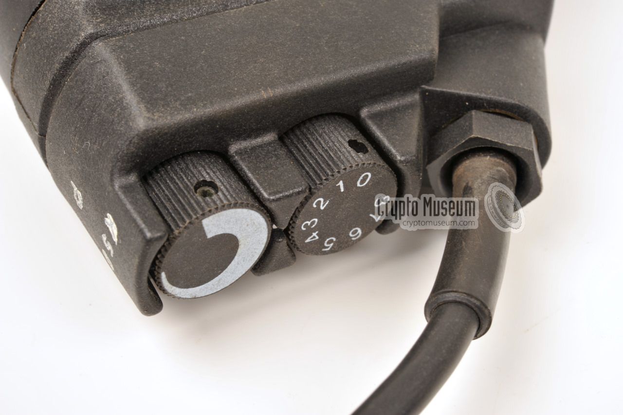
The SPIDER can receive and transmit on 9 preset frequencies or channels.
Once programmed, the required channel can be selected in two ways: directly from
the keypad, or (when using the special extended handset),
via a rotary selector on the handset. This rotary selector has 9 settings (0-8).
In positions 1 to 8, the corresponding channel is selected directly and channel
selection via the keypad is disabled. In position 0, the channel can be
selected via the radio's keypad.
|
The frequency for each of the 9 preset channels can be set with the
FREQ-function. Please note that this function is protected against accidental
changes. Before altering the frequency, select the required channel and
press the F-key to enter Function-mode. Then press FREQ, enter the frequency
(e.g. 52.100 MHz) en press ENT to confirm. This sequence is illustrated below:
|
The receiver has a noise canceller (squelch) that can be switched ON and OFF
by the user. The treshold level is preset and can not be
changed by the user. Simply press the SQ-key to turn the squelch ON and press
it again to switch it OFF. The current squelch state is shown in the display.
Note that the squelch will only open automatically if a 150 Hz CTCSS tone is
received.
|
If the crypto option is fitted, cryptograhics keys will be stored in the
radio's non-volatile memory. If security is compromised, it may be
necessary to destroy the keys, so that they can not fall into enemy hands.
This is done by ZEROIZING the radio. As per convention, this is a 2-step
process: Rotate the VOLUME control to the Z and hold it in that position,
whilst simultaneously pressing the Z-button below the display.
Once ZEROIZED, secure communication is no longer possible.
|
The basic (manpack) version of the SPIDER radio set, is shown in the image
on the right. It measures just 240 x 175 x 66 mm and weighs 3.4 kg,
including Alkaline batteries.
The radio can optionally be expanded with a crypto board,
in which case the height is extended to 82 mm (rather than 66 mm).
|
|
|
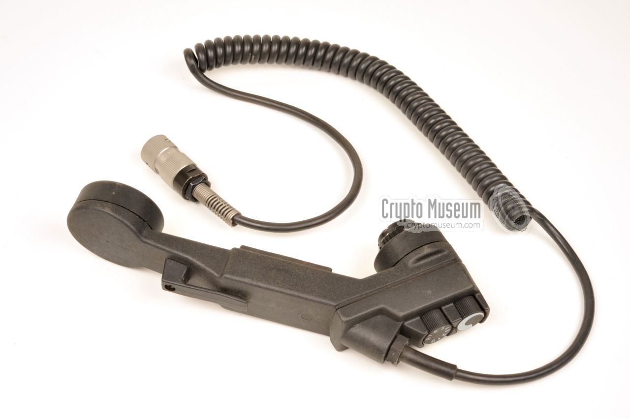
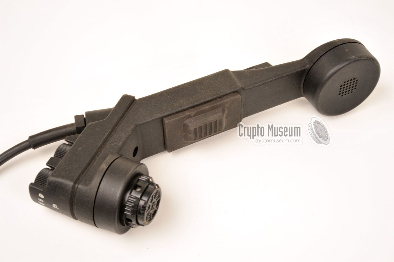
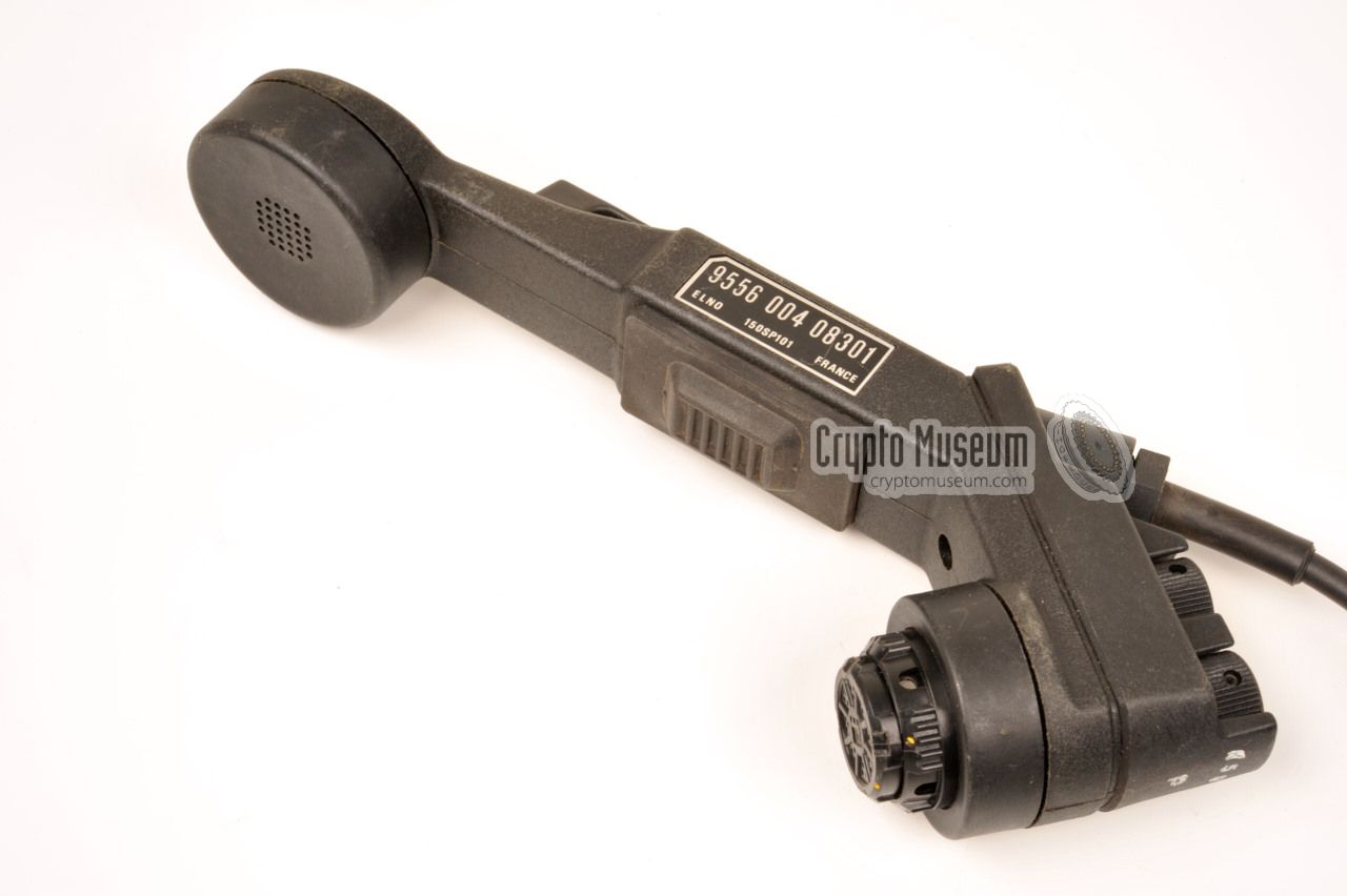
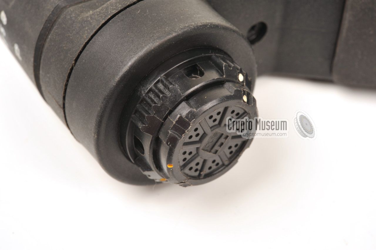
Although the SPIDER radio can be used with virtually any type of handset
with a U-229 connector, it was generally supplied with the enhanced one
shown in the image on the right, which has remote control facilities.
Apart from setting the speaker volume, any of 9 preset channels can be
selected directly from the handset, whilst the operator carries the radio
on his back using the special manpack harness.
|
|
|
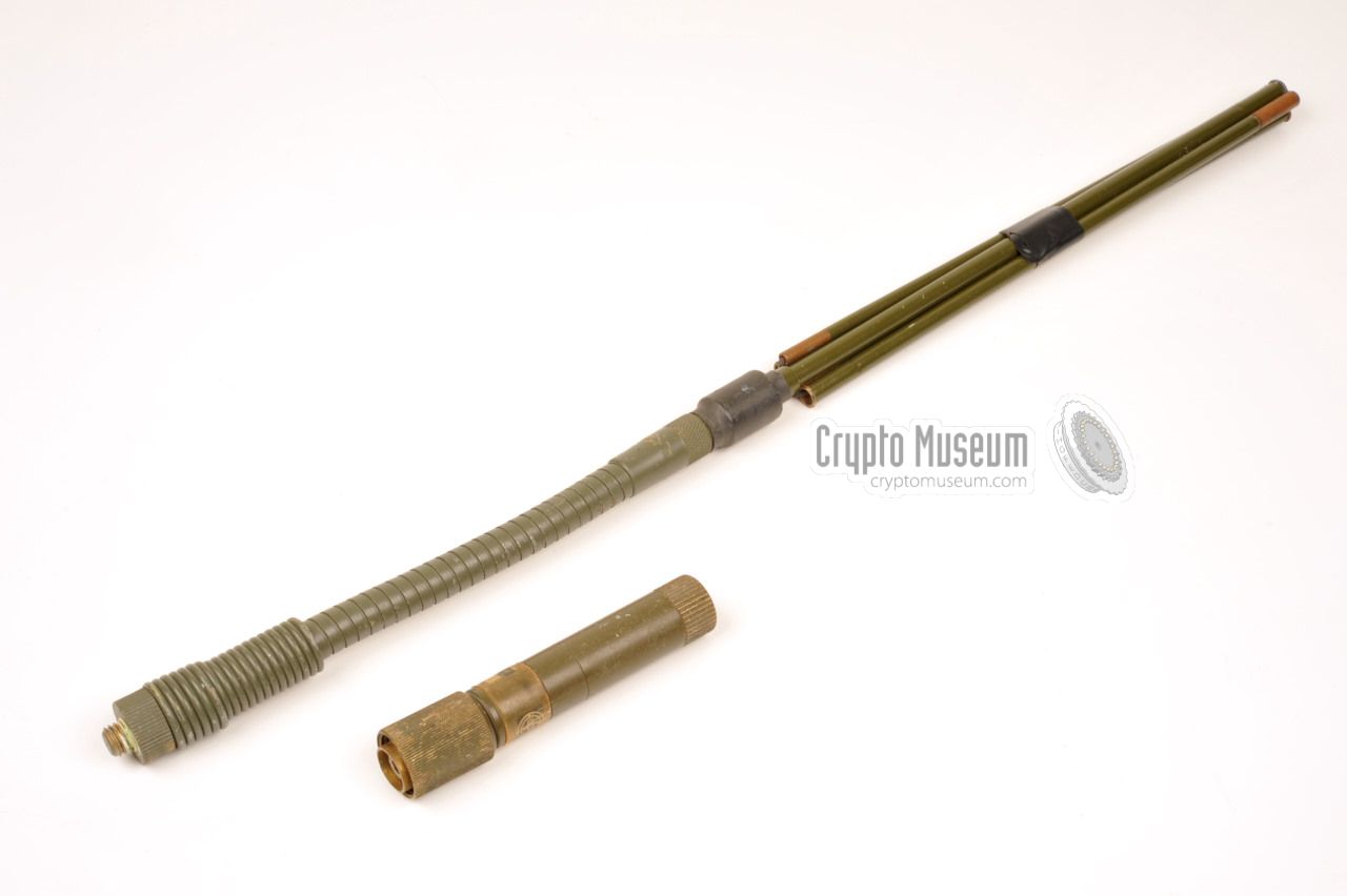
For connection of an antenna, a standard BNC socket is available at the
top right of the front panel.
Apart from an external vehicle antenna,
this socket is also suitable for a wide-range manpack antenna rod that is
screwed in place.
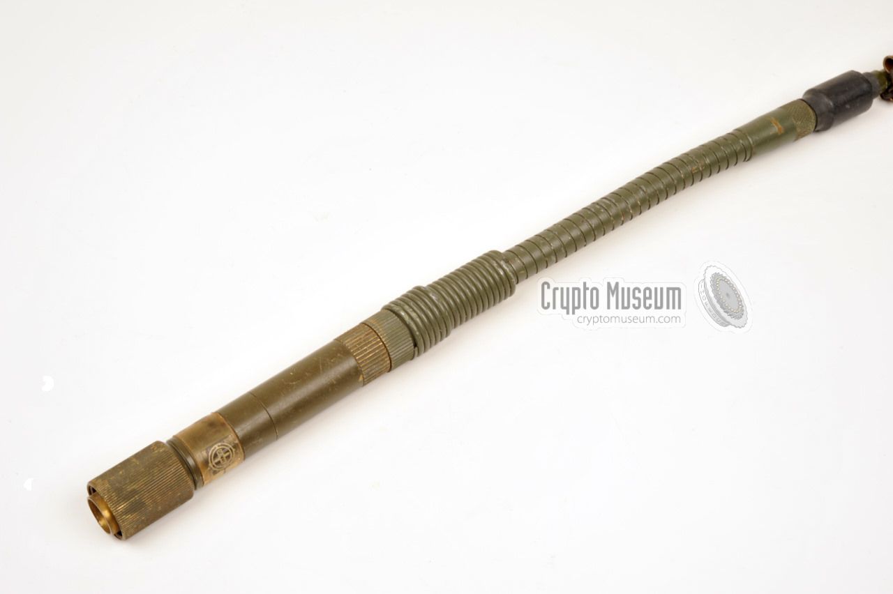
The antenna consists of three parts: an
Antenna Matching Unit (AMU)
as shown here, a gooseneck
and a five-piece antenna rod
that is approx. 1.5 m long.
The gooseneck is mounted between the AMU and the rod,
and is an active part of the antenna. It allows the
antenna to be bended during military operations.
|
|
|
|
|
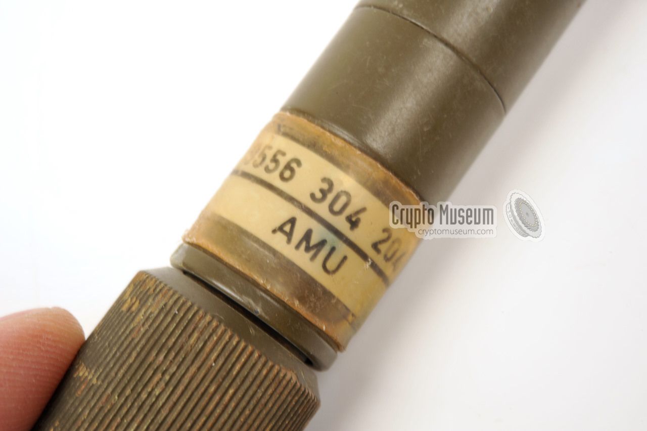
Antenna matching unit
AMU
|
|
|
When using the SPIDER radio in manpack configuration, the Antenna Matching
Unit (AMU), shown in the image on the right, has to be fitted between
the BNC socket on the radio's front panel and the rod antenna shown
above.
At the lower end, the AMU has a BNC plug with screw fitting, that mates with
the BNC socket on the SPIDER. At the top, it has a threaded hole for
the gooseneck of the rod antenna [J][K][L].
➤ AMU circuit diagram
|
|
|
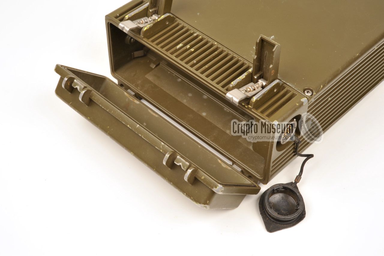
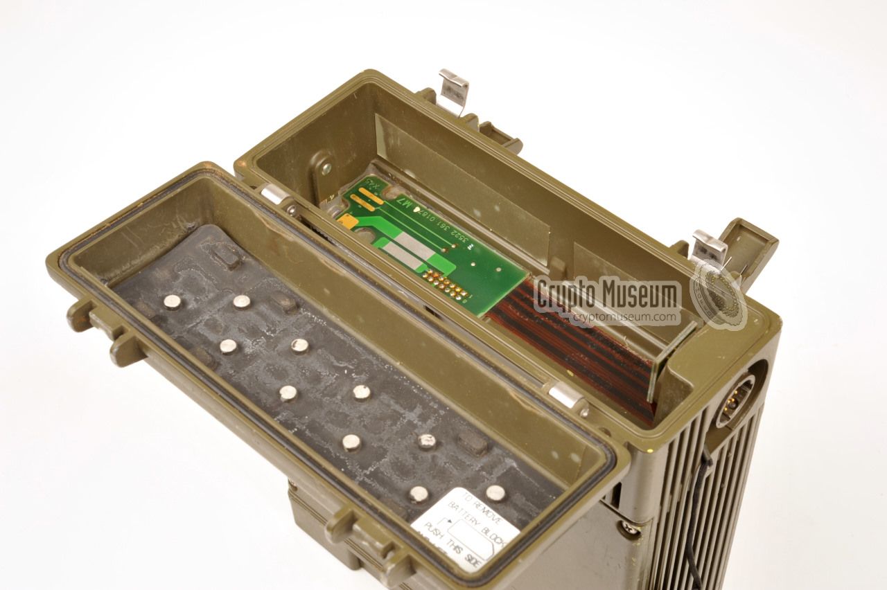
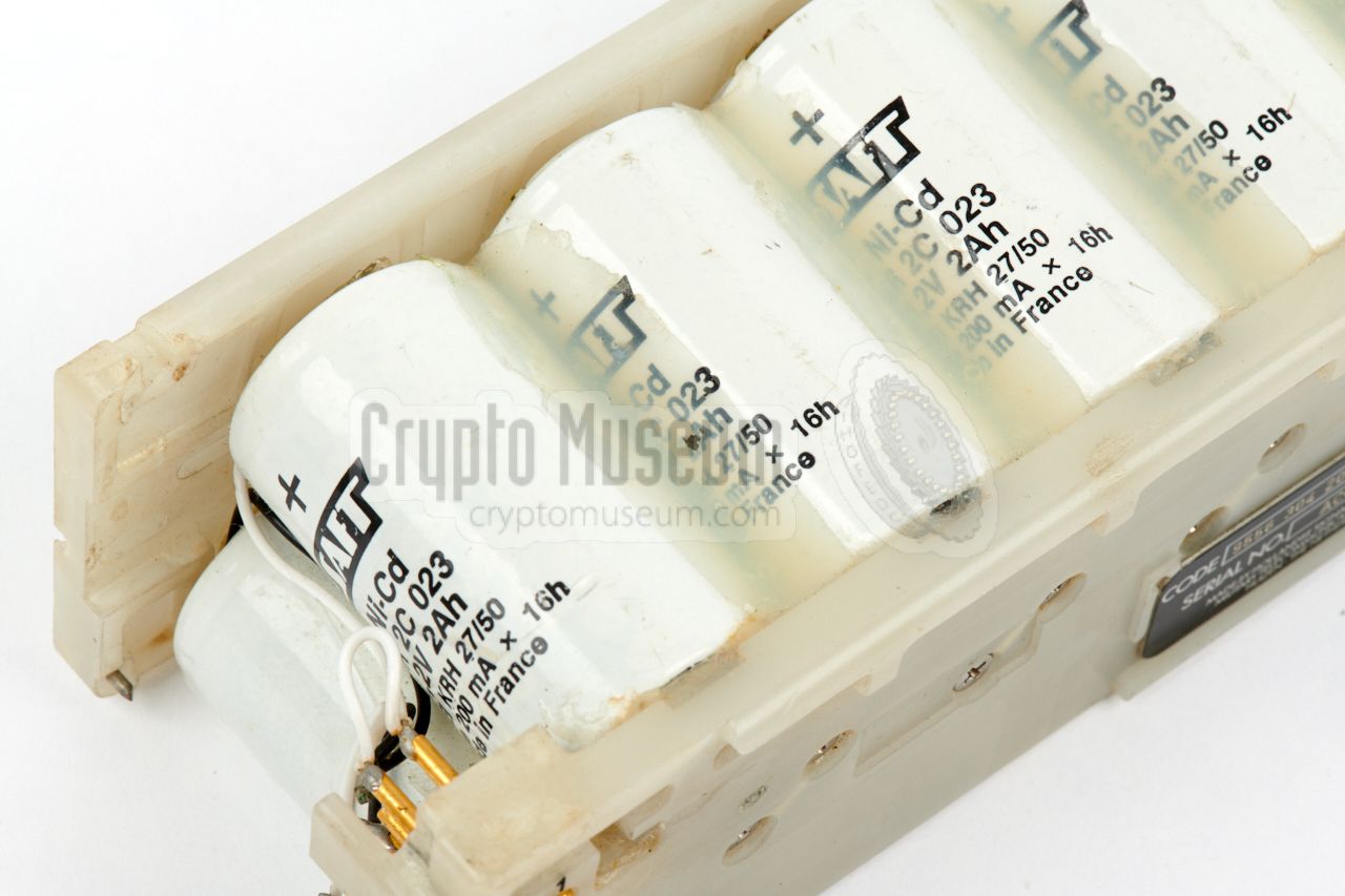
When used as a manpack radio, the SPIDER is powered by an internal 12V battery
that was placed inside the battery compartment, at the radio's rear end,
behind a hinged panel.
Two types of battery were available: (1) a dry non-chargeable Alkaline battery
pack and (2) a rechargeable NiCd battery pack. The latter is shown in the
image on the right.
|
|
|
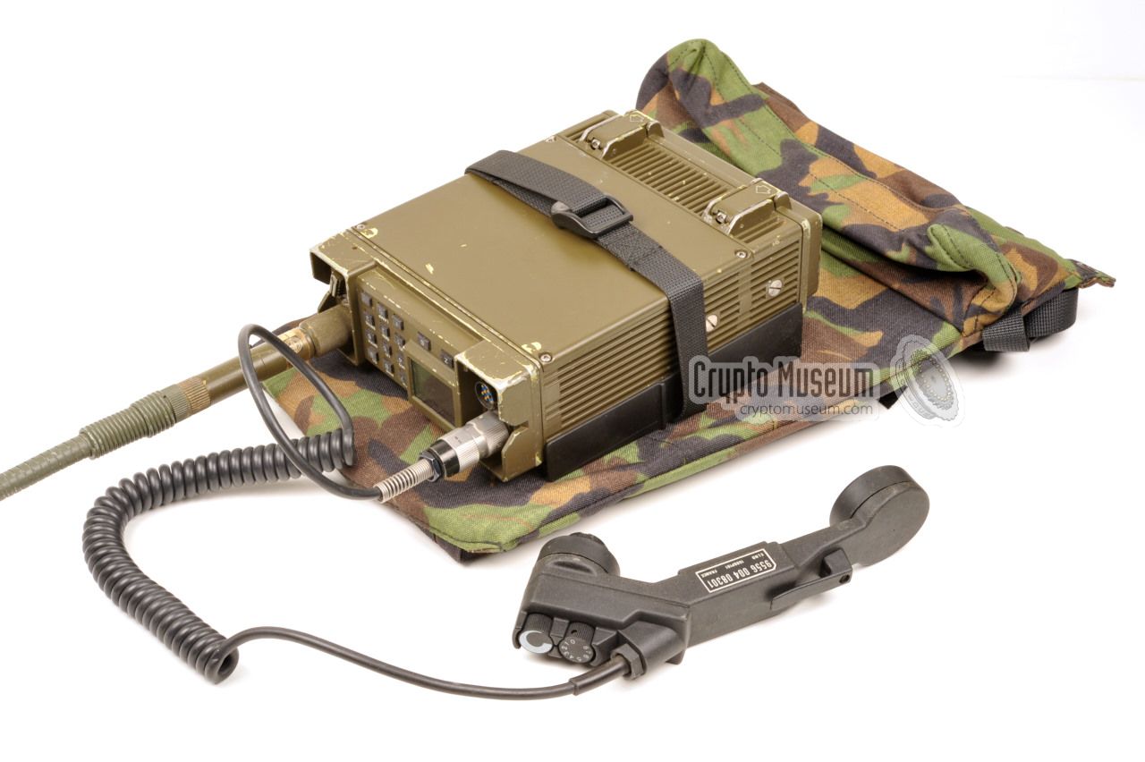
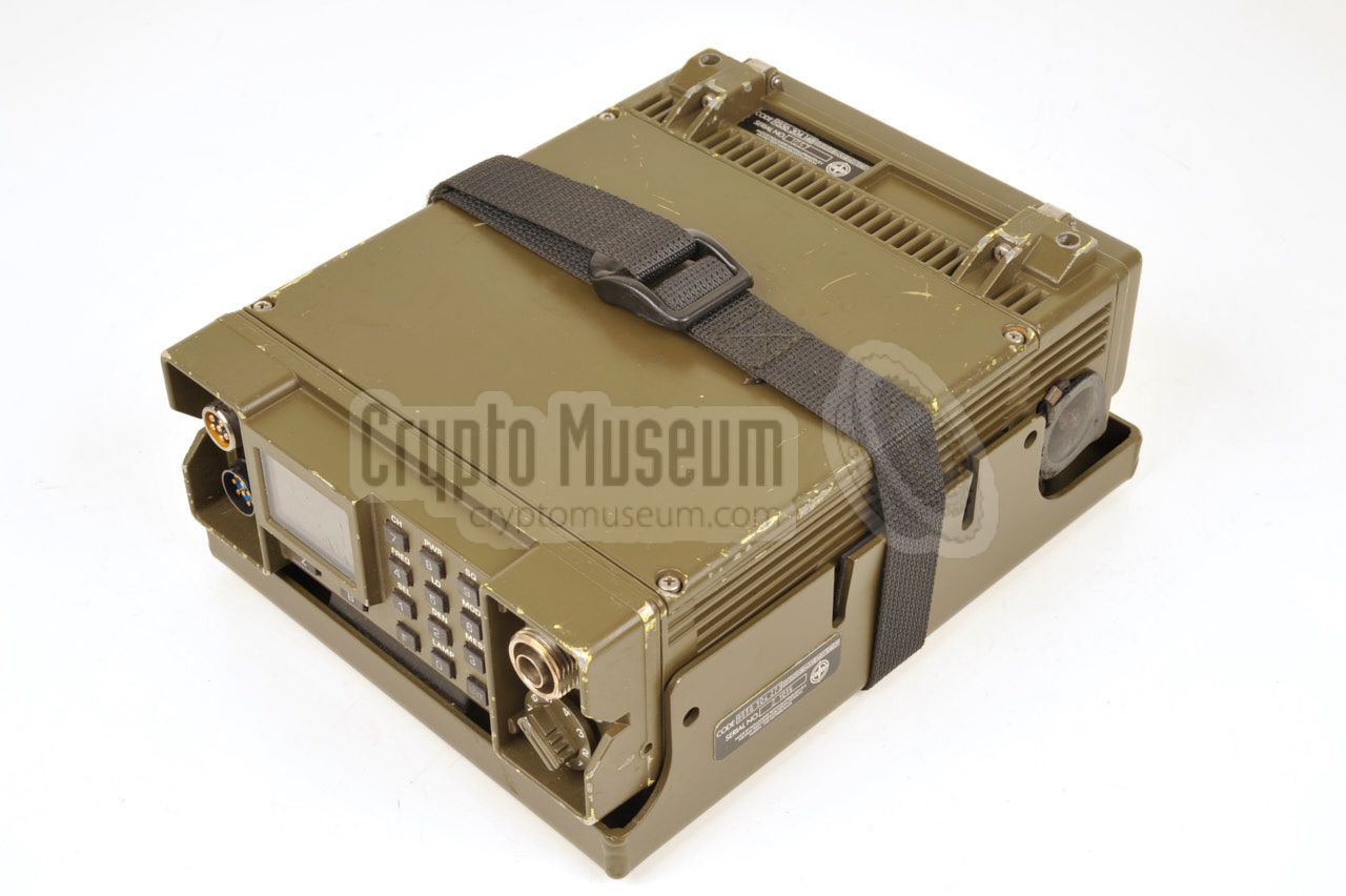
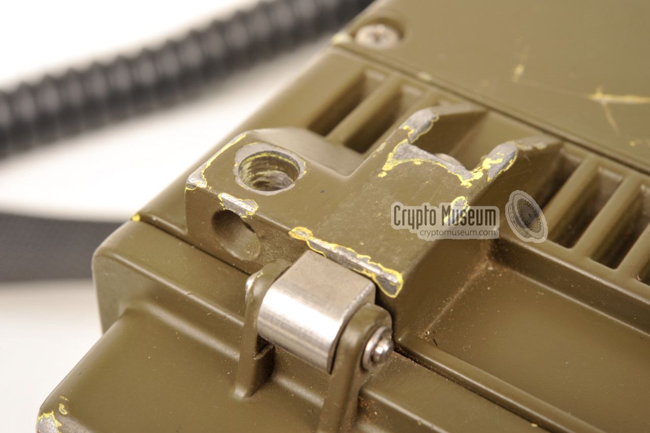
A portable SPIDER manpack radio could easily be converted to
a vehicular radio set,
by mounting it inside a special frame
that in turn is mounted inside a vehicle.
The radio is held in place
with a velcro strip at the top.
The vehicle bracket was normally used in combination with a special
24V DC vehicular power supply unit (PSU), a vehicular antenna and
suitable cables, all of which are described in manual HTG5-2541e [E].
The image on the right shows how the radio was fitted inside the special
vehicle mounting bracket. The matching Vehicle PSU is shown below.
|
|
|
For infantry use (manpack), the radio can be powered by any DC source
between 9 and 16V (typically 12V). When used as a vehicular radio set
however, a special Power Supply Unit (PSU) is needed in order to power
the set directly from the 24V battery of a tank or truck.
The 24V PSU is mounted externally and connects to the
10-pin Supply Connector
at the side of the radio. It accepts a DC voltage in the range 22 to 33V,
which is converted into 14V DV for the radio. Features and installation
of the Vehicular PSU is described in manual HGT5-2541e [E].
|
|
|
|
|
Remote control set
GRA-3686(S)
|
|
|
SPIDER could be remote operated via a modified KL/GRA-3686
Remote Control Set (RCS) 1 ,
that was originally developed for the
RT-4600
and for the earlier RT-3600
military radio sets.
The image on the right shows the C-3686A, which is one half of the
modified KL/GRA-3686. It can be connected to one or two SPIDER radios,
via the 10-pin sockets at the left.
➤ More information
|
|
|
-
In Dutch known as Afstandbedieningsapparaat (ABA).
|
|
|
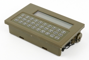
Message exchange device
MED
|
|
|
If voice communication (speech) is undesired or simply not
possible (e.g. during reconnaissance missions), the digital Message
Exchange Device (MED) shown in the image on the right could be used
instead. It has a built-in FSK modem that converts the digital signals
into audio tones.
The MED has built-in crypto facilities and does not require the
(optional) crypto/data board in the SPIDER itself. It is completely
self-contained.
➤ More information
|
|
|
For the message terminal (MED) shown above, an external thermal
printer was available, which is shown in the image on the right.
It consists of a commercial-off-the-shelf (COTS) printing unit,
housed in a die-cast aluminium enclosure.
It is currently unknown whether this printer was ever made in large
quantities. Furthermore, it is likely that the one shown here,
is a prototype, as it has a fixed cable with a DB25/F connector
at the end, whilst the MED has an NF7 connector.
|
|
|
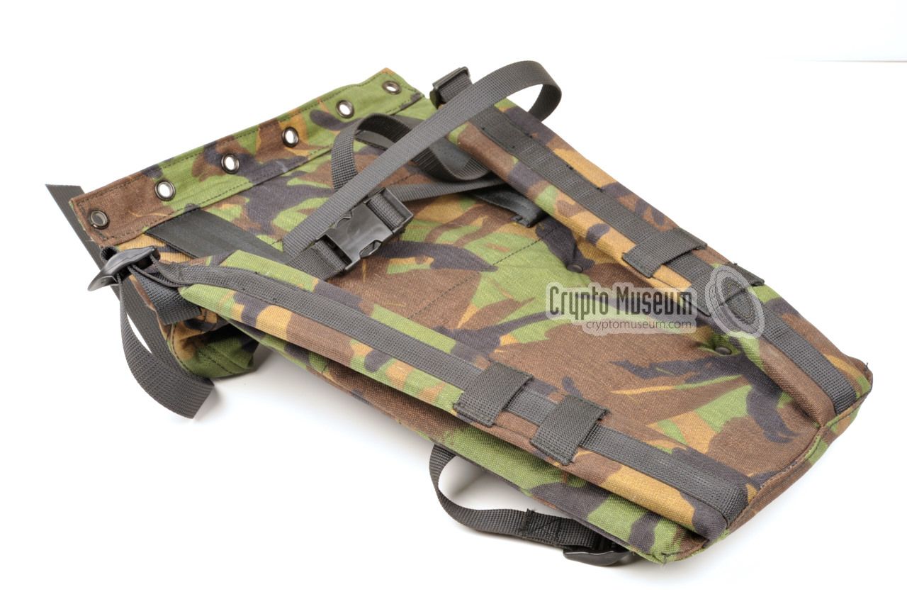
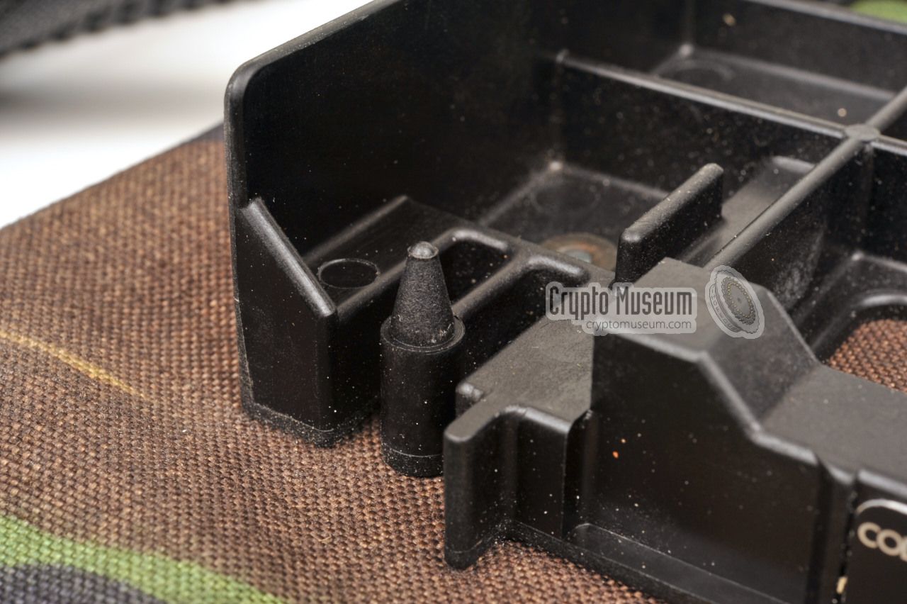
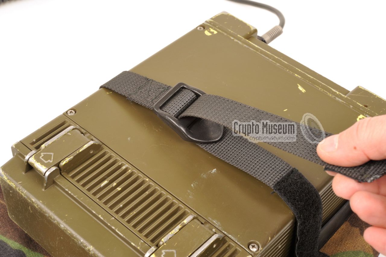
This manpack can be used to carry the radio
at the operator's back. The plastic frame that holds the radio, has
two alignment pins
to prevent the radio from slipping out, and a velcro
strip to keep it in place. Furthermore there
is a zipper bag for the accessories and for a spare battery.
When carried on the back, the radio is facing outwards, so that it
can be operated by another member of the team.
When used in this way, the enhanced handset
is recommended, as it allows the operator to select the channel and set
the audio volume without accessing the front panel.
|
|
|
|
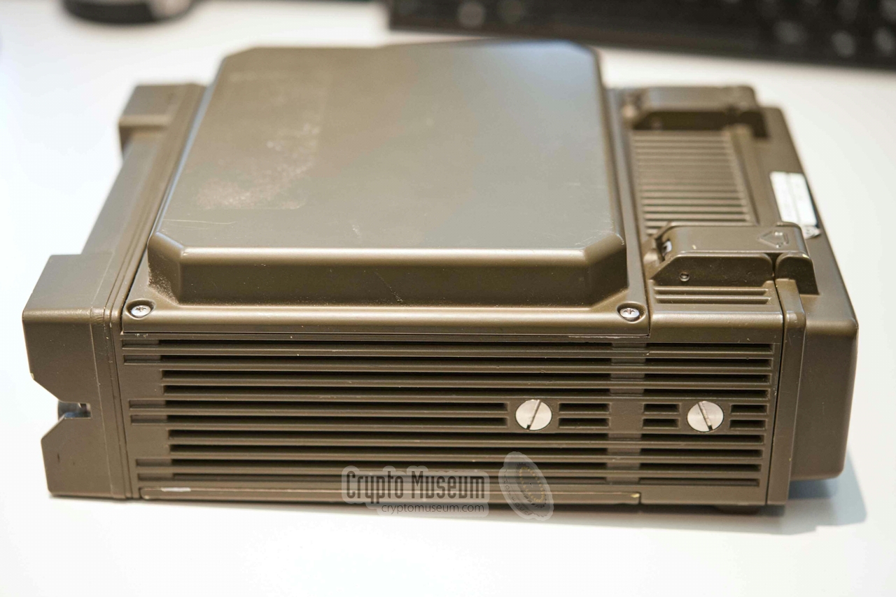
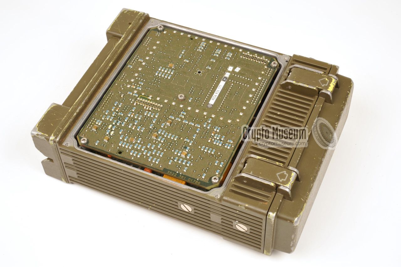
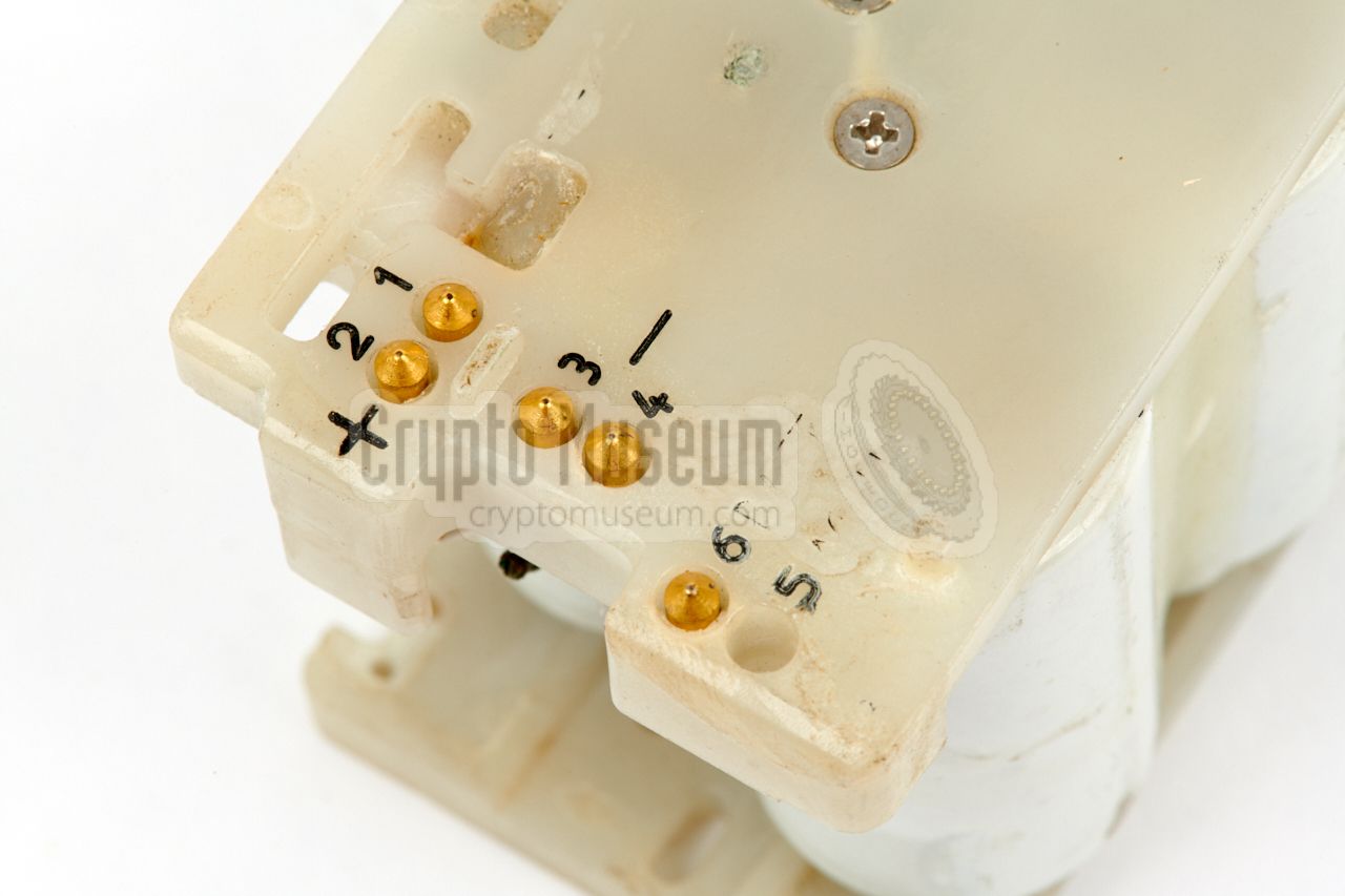
The standard version of the radio does not have encryption/decryption
facilities, but can be extended by installing an optional crypto/data board.
This board adds several other features as well, and
is mounted at the bottom of the radio, on top of the
existing Audio/CPU board.
|
It connects to the Audio/CPU board by means of two internal
20-pin headers. As a result, the bottom lid of the case has to be
replaced by a variant with a 'blob' in order to accomodate the board.
The crypto-variant of the radio can easily be recognised by the thicker
bottom panel.
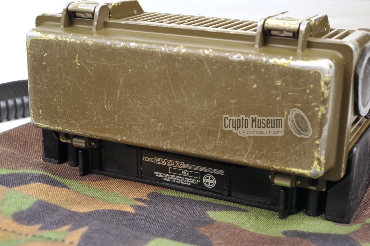
The image on the right was kindly supplied by Egbert Spaa (PE1OSF) [6],
and shows the bottom side of his SPIDER radio, with the bulged bottom
panel installed. Inside this thicker panel is space for the optional
crypto/data board, which is unfortunately missing from the device shown here.
|
|
|
When the crypto/data board is present, the extra functions of the keypad
(LD, MODE, SEL, GEN and MESS) become available. The additional features
of the expansion board are explained in a separate manual [H] which we
have not been able to uncover yet. The Spider crypto module was developed by
the Crypto Division of Philips Usfa in Eindhoven, and was known
as UP-2094 [5].
As far as we know, no surviving examples of the UP-2094 crypto module have
been found so far.
The crypto/data board adds the following features:
|
- High-speed data transfer
- Voice encryption/decryption
- Low-speed data encryption
- Burst transmission of pre-coded messages
- Selective calling
|
|
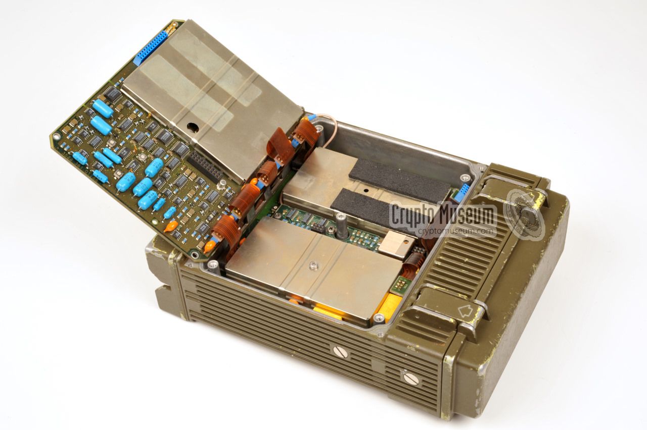
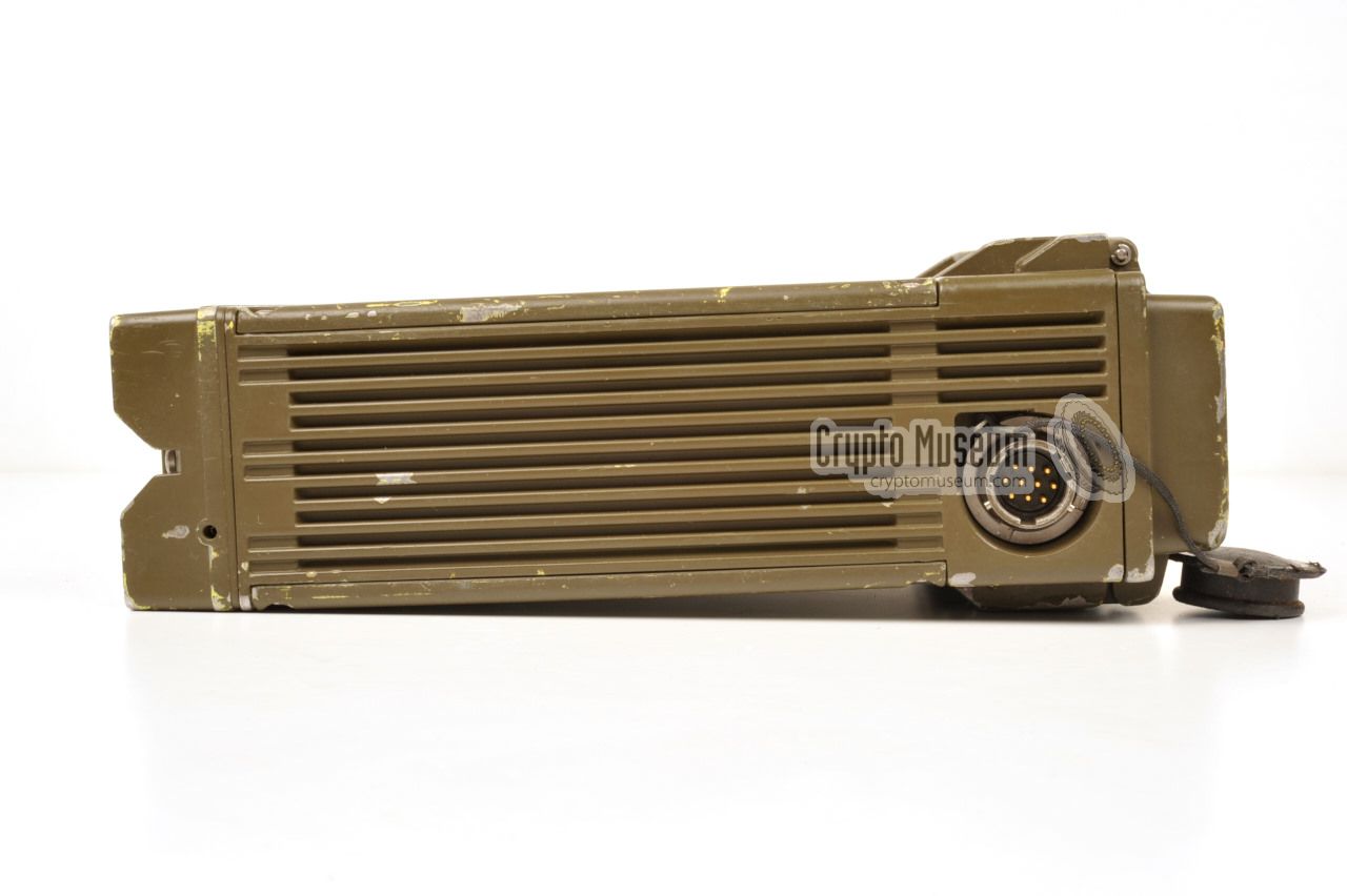
The highly compact SPIDER radio is housed in a die-cast aluminium enclosure,
that consists of two large sections, one at the top and one at the bottom,
a battery compartment at the rear and a removable front panel.
The top and bottom sections are covered by sealed aluminium panels.
|
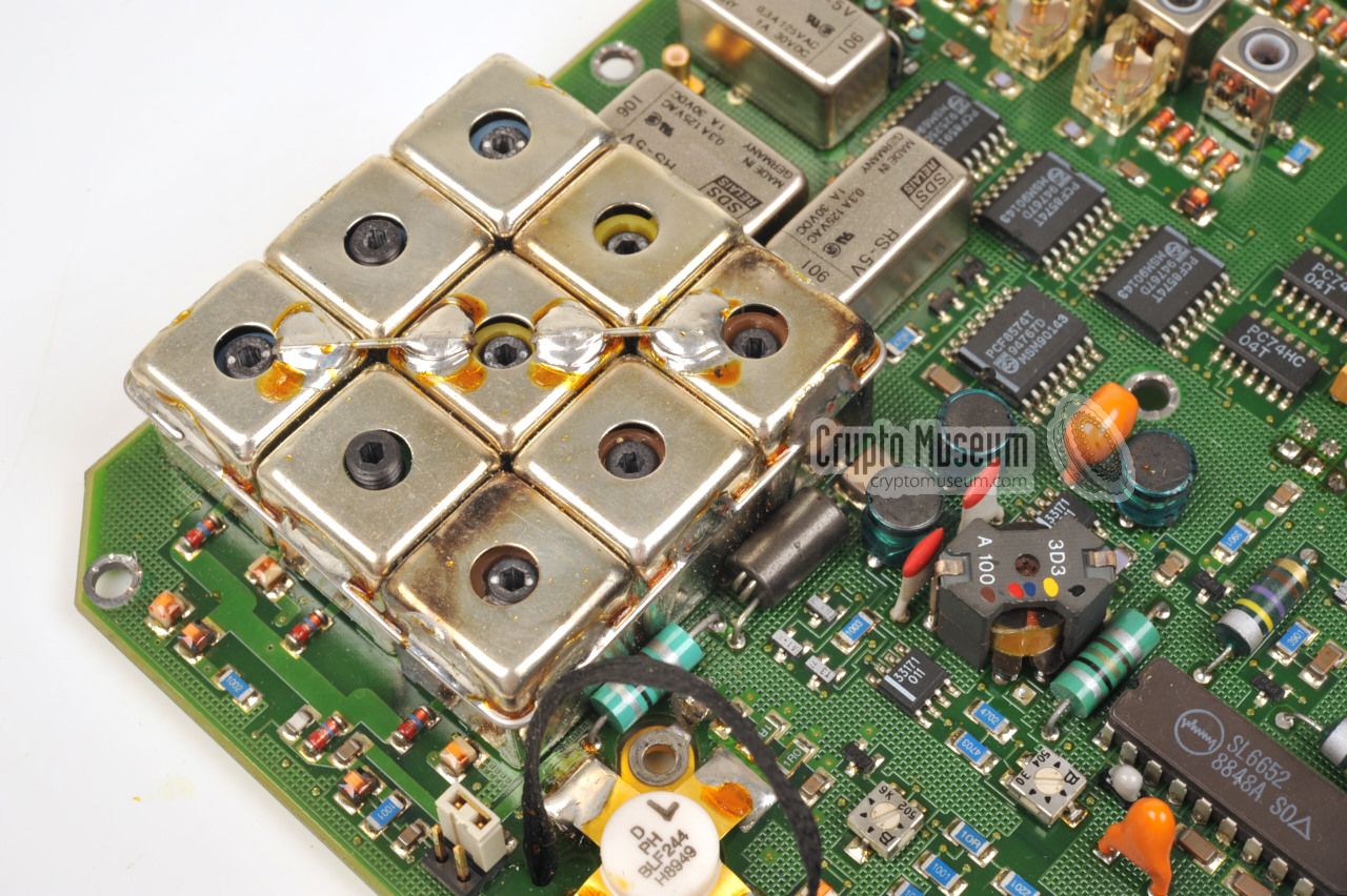
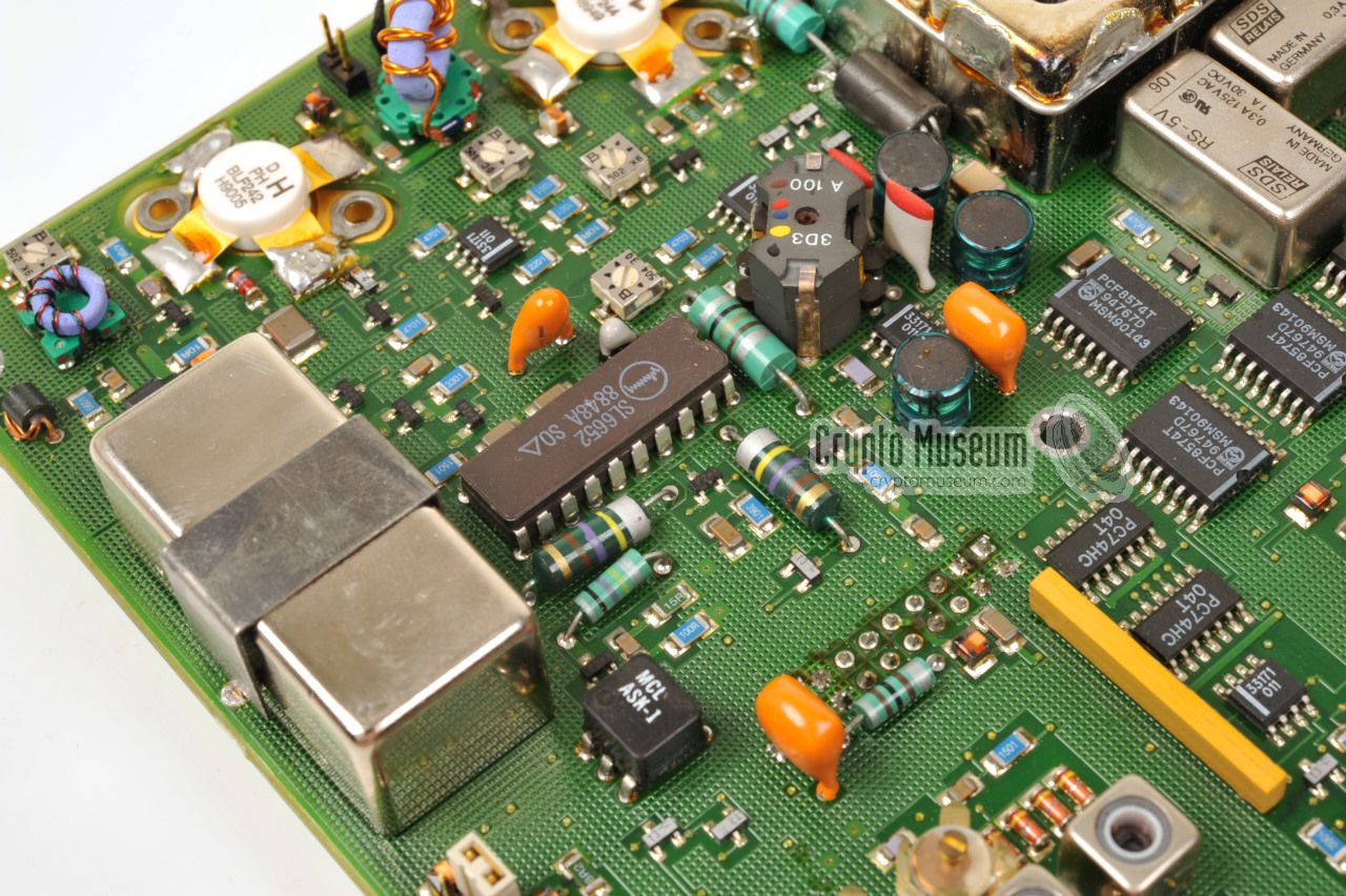
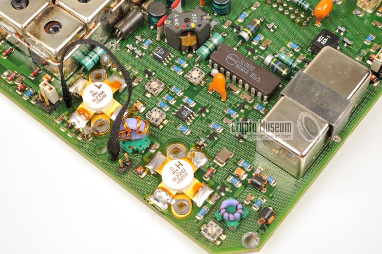
After loosening the four screws at the corners of the top panel, the upper
compartment can be accessed. It contains the RF section of the transmitter
and the receiver on a single board, as shown in the image on the right.
The antenna connection is at the bottom left. At the bottom right of the
board are two RF power transistors BLF242 and BLF244. The Power Amplifier
(PA) has been dimensioned in such a way that it survives a full short
or a non-terminated output.
The RF board can be extracted
after removing 4 bolts in the corners, one
at the centre and four smaller ones around the
power transistors.
|
|
|
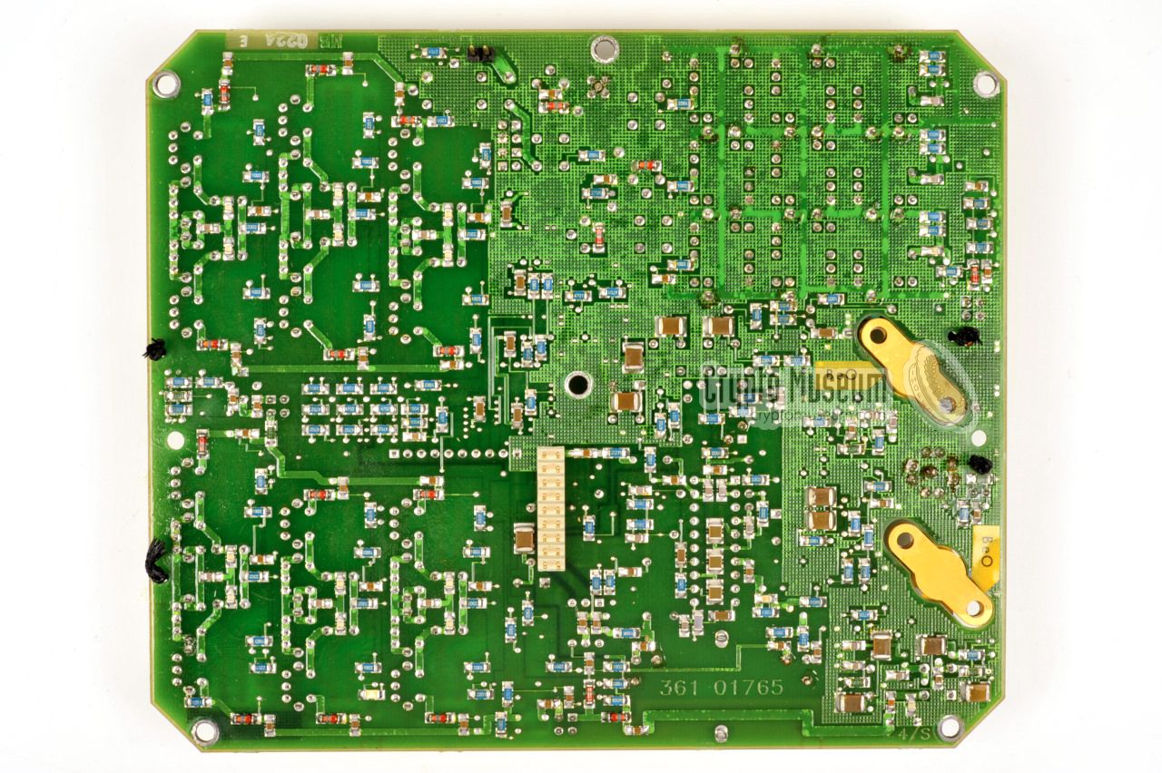
Most of the components are fitted to the
top side of the RF board, but
some smaller parts, mainly resistors, capacitors and diodes, are fitted
at the bottom.
At the centre of the bottom side is a 18-pin header that
connects the RF board to the EXC/SMPS section
at the other side.
|
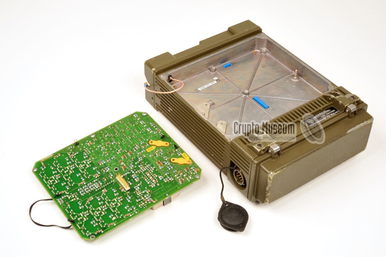
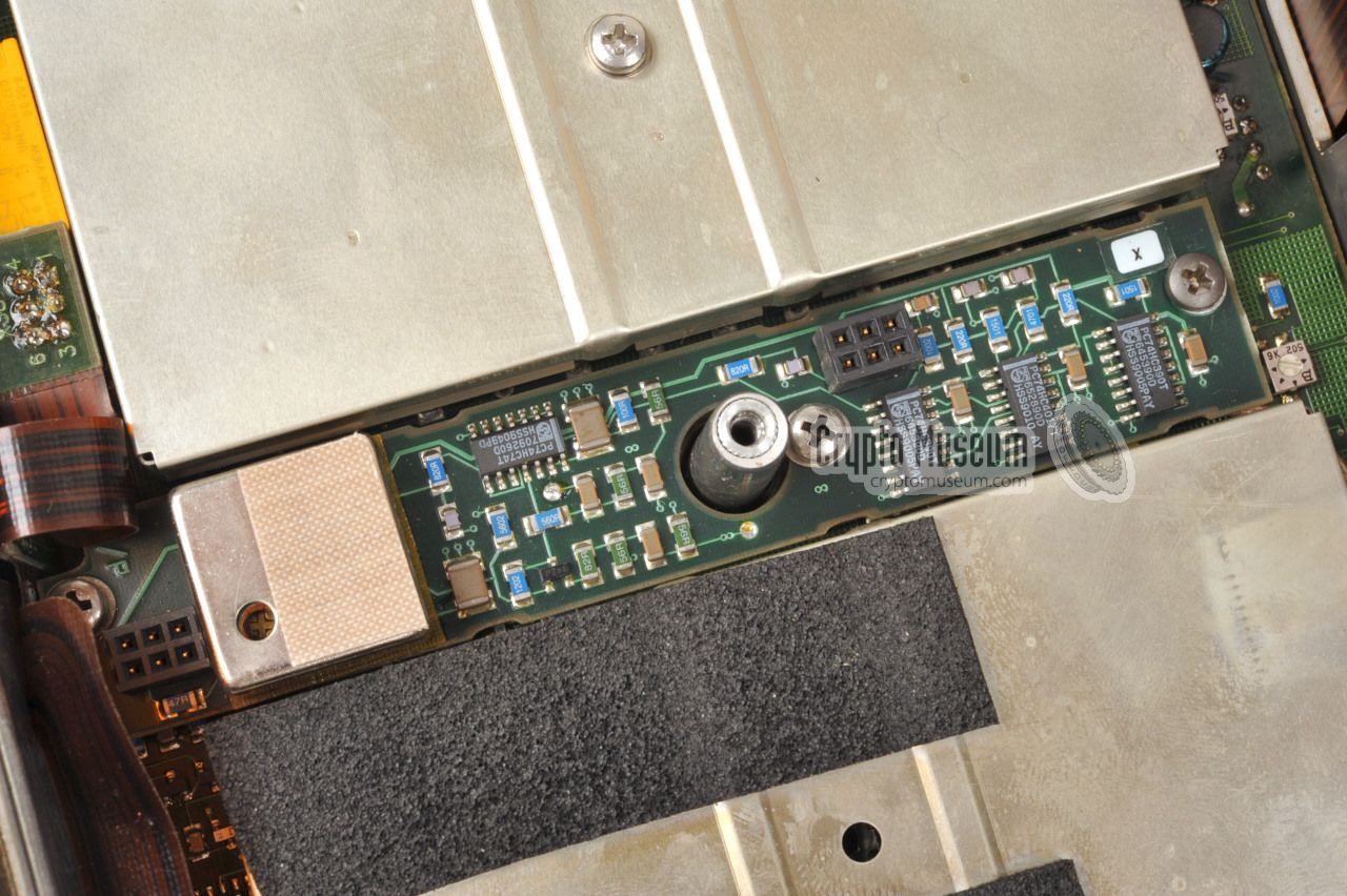
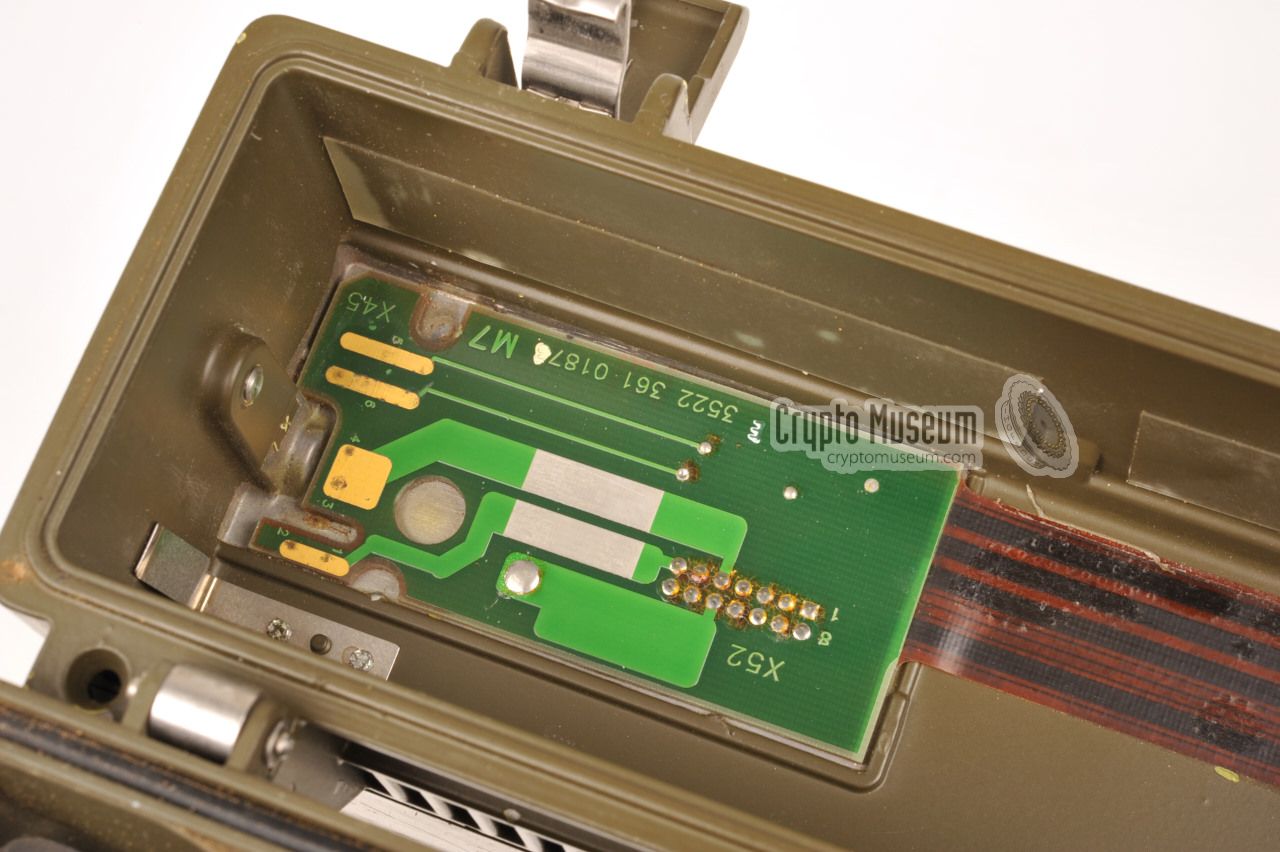
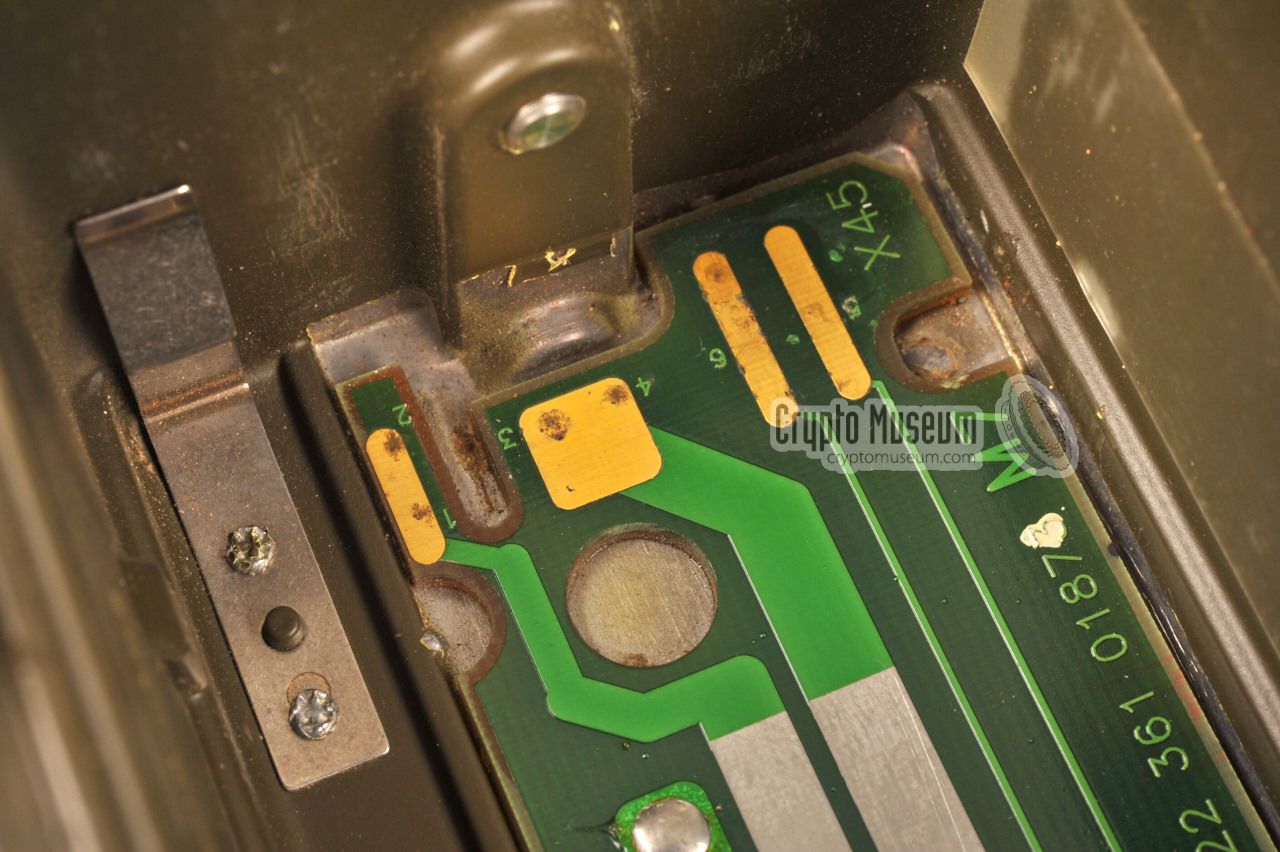
All other parts are located at the bottom side of the radio and can be
accessed by removed the bottom lid. The image on the right shows the
radio's bottom side with the Audio/Logic board
partly removed at the left.
This board connects to the radio's front panel by means of flex PCBs.
Inside the radio
is a large board that holds the
internal SMPS power supply 1 ,
the exciter and the synthesizers.
Mounted on a separate PCB at the centre is the
reference oscillator.
Note that the SMPS and the synthesizers are individialy shielded
in order to avoid RF and IF interference.
|
|
|
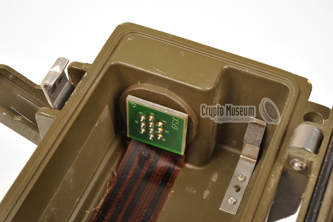
The Audio/Logic board has two 20-pin sockets
that are positioned in such a way that they can be accessed from
the solder side of the PCB. When the Audio/Logic board is
mounted in place, the (optional)
Crypto/Data board can be fitted on top, connecting to these two
20-pin sockets.
|
-
SMPS = Switch Mode Power Supply.
|
The simplified bock diagram below shows how the various parts
of the SPIDER are connected together. At the left is the LF/Control
board that contains the audio section as well as the microcontroller
which is separately shielded in order to avoid interference.
The front panel is connected directly to this board by means of
several flex PCBs and dual-row headers.
At the right are the IF/RF sections and the internal SMPS power supply.
At the center is the reference oscillator that provides the various
frequencies needed by the other boards. It is
mounted as a separate board at the center of the EXC/SMPS board.
For a more detailed overview of the connections between the various
boards, please refer to the original block diagram [I].
|
|
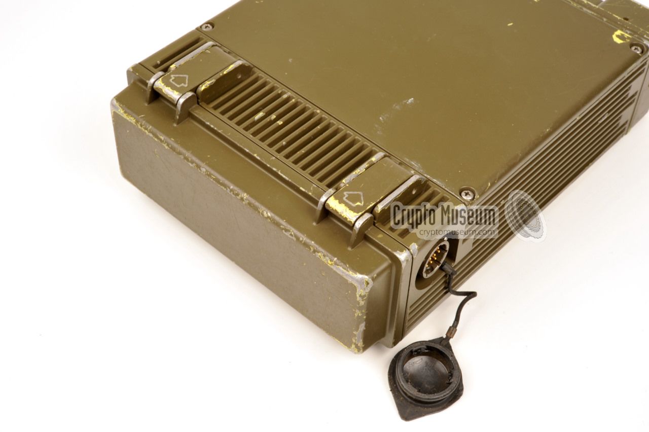
The SPIDER manpack radio has a total of four connectors, three of which are
located at the front panel. The fourth socket is located at the right rear.
Pinout and specifications of the connectors are given below. The following
sockets are present:
|
|
This is a standard 50Ω BNC socket with an additional threaded ring,
allowing a short manpack antenna rod with extension coil to be used directly.
When used in a vehicle, a normal BNC plug can be connected directly.
The antenna input/output is suitable for the entire 30-108 MHz range.
|
|
At the top left of the front panel is a U-283/U
male audio socket for connection of a microphone, headset or handset.
Whilst it follows the standard US/NATO
U-229 conventions for pins A to D,
pins E and F are used for additional features here.
Also note that the pinout of this socket is different from the earlier
RT-3600 radio.
This socket is not used for connection of a
FILL unit.
|
GND Common ground SPK Audio out 1 PTT Transmit contact MIC Audio in 2 SQL Squelch contact 3 CH Channel preset selection 4
|
|
-
2V RMS into 500Ω.
-
Sensitivity deping on setting.
-
This is an open-collector output which can be used for retransmissions.
-
A resistor in the handset determines the selected (preset) channel.
|
|
Pin F of the 6-pin U-229 connector of the handset can be used to select
one of the 9 preset channels. This is done by connecting a resistor (with
an accuracy of 2%) between this pin and ground, using the following table:
|
no resistor Channel 0 - selection via keypad 470 kΩ Channel 1 180 kΩ Channel 2 100 kΩ Channel 3 68 kΩ Channel 4 47 kΩ Channel 5 33 kΩ Channel 6 22 kΩ Channel 7 15 kΩ Channel 8
|
|
|
In addition to the 6-pin audio socket shown above, the SPIDER also
has a 10-pin NF10 audio socket which allows a wider variety of peripherals
to be connected to the radio. When the (optional) crypto unit is
fitted, this socket is also used for connection of a FILL gun
and for data.
|
GND Common ground SPK Audio output PTT Transmit contact MIC Audio in SQL Squelch contact NOGO 'NOGO' information (active low) - not connected ADR Peripheral address 2 PWR +12V supply for peripheral DATA 'Data mode' information (active low)
|
|
-
The V24/28 data interface is only available when the
crypto/data unit is fitted and DATA-mode is selected.
-
A 2% resistor between this pin and ground selects the
required operation (see below).
|
|
|
Peripheral address
on the 10-pin audio socket
|
|
|
|
As the 10-pin audio socket at the left bottom corner of the front panel
can be used for the connection of various types of accessories, such as
handset, data terminal and FILL unit, a 2% resistor may be connected
between pin H and ground to select the required function:
|
no resistor Handset or headset 470 kΩ Retransmission cable 180 kΩ Message exchange device 68 kΩ Intercom system 33 kΩ FILL gun
|
|
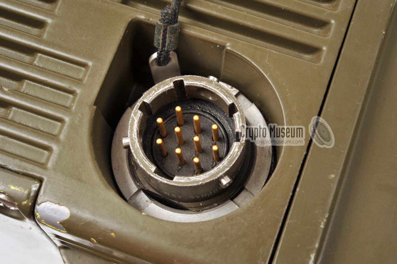
At the right side of the radio, a 10-pin male socket is available for
connection of an external power supply unit and/or peripheral equipment,
such as a remote control unit or test equipment.
|
- External supply ground 1
- External supply input (+10 to +15V DC) 1
- Battery recharge current input (max. 100mA)
- Data ground 2
- Data output 2
- Data input 2
- +5V DC output for peripheral use
- Peripheral address 3
- Common ground
- not connected
|
|
-
Internally connected if external supply is present with correct polarity.
-
Data interface for control of peripheral equipment (V24/28, 2400 baud).
-
A 2% resistor (connected to ground) determines the function of the interface (see below).
|
|
|
Peripheral address
on the power socket
|
|
|
|
As the Supply/Peripheral socket at the right rear can be used for a variety
of purposes, a sensing resistor 1 (usually mounted inside the peripheral or
its cable) should be connected between pin H and ground to select the
required operation. The following addresses have been assigned:
|
no resistor Supply cable 47 kΩ Remote control 6.8 kΩ External equipment 2.2 kΩ Test equipment
|
-
The sensing resistor should have an accuracy of 2%.
|
By using an appropriate retransmission or crossover cable,
two SPIDER radios can be combined to form a repeater or
transponder.
This can be used, for example, to extend the range between a platoon
and the base camp, or for connecting two different radio nets. This is
done by crossing the audio in/out connections as well as connecting the
PTT of each set to the squelch contact (SQL) of the other one.
The pinout of a suitable retransmission cable is given here:
Retransmission is also possible by linking two radios via the 10-pin
audio connector, in which case a 470 kΩ resistor has to be mounted
inside the connectors in order to enable the appropriate function.
This is the recommended method. The wiring is as follows:
|
|
-
Developed by Philips Crypto in Eindhoven (Netherlands),
according to Philips Crypto drawing 4322 082 51510.
|
Frequency 30.000 - 107.975 MHz Spacing 25 kHz Channels 3120 Presets 9 Modulation FM Deviation 5 kHz (nominal) Speech 300 - 3400 Hz Squelch 150 Hz CTCSS Power 12V nominal (9V-16V DC) Storage -40 to +70°C Operation -30 to +65°C Dimensions 240 x 175 x 66 mm (with crypto: 240 x 175 x 82 mm) Weight 2.6 kg (3.4 kg with batteries, 5 kg for complete manpack)
|
Sensitivity 0.4µV (at 10dB SINAD) AF output max. 2V RMS into 500Ω Rejection 60dB or better Selectivity 60dB or more suppression of signal ±25kHz from RX frequency Current approx. 140mA
|
RF output 4 levels: 20mW, 200mW, 2W, 5W Impedance 50Ω Max. SWR 4:1 Harmonic 50db or better suppression (60-400MHz) Current 1.2A at 2W output (2A at 5W output)
|
|
AMU
|
|
Antenna Matching Unit
Small unit that is fitted between the antenna socket and the actual
antenna rod. It makes the antenna rod suitable for the full frequency
range of the radio.
|
|
CTCSS
|
|
Continuous Tone Coded Squelch System
Continuous sub-audible sinewave tone, added to the audio signal of a
transmitter, in order to open the squelch of the receiver. In the case
of SPIDER (and the older RT-3600) a 150 Hz tone is used.
|
|
FM
|
|
Frequency Modulation
|
|
HSA
|
|
Hollandse Signaalapparaten.
At the time a Philips subsidary.
Sold in 1990 to Thomson (now: Thales).
|
|
IF
|
|
Intermediate Frequency
|
|
LCD
|
|
Liquid Crystal Display
|
|
LD
|
|
Load
This function is used for loading cryptographic keys. It requires the
optional crypto/data expansion card to be fitted.
|
|
LF
|
|
Low Frequency
Also known as AF (Audio Frequency).
|
|
PCB
|
|
Printed Circuit Board
|
|
PSU
|
|
Power Supply Unit
|
|
PWR
|
|
Power
In this context, PWR is used for setting the transmitter's
RF output power.
|
|
PTT
|
|
Push-To-Talk
General expression for the tranmit button on the handset, headset or
microphone.
|
|
RF
|
|
Radio Frequency
|
|
SF
|
|
Special Forces
|
|
SQ
|
|
Squelch
Noise cancelling system.
|
If you have any additional documentation, circuit diagrams, leaflets,
crypto expansion, accessories, etc.,
please contact us. We are also looking for photographs of the
items that are missing from this page. Any additional information is much
appreciated.
|
- SPIDER Leaflet
HSA, October 1989. 2 pages. 2
➤ Older version of October 1987 1
- SPIDER Instruction Card
HGT5-2528e. HSA, date unknown. 1
- SPIDER Manpack Transceiver - Operators Manual (provisional)
HGT5-2515e. HSA, December 1988. 39 pages. 1
- SPIDER Manpack Transceiver - Operators Manual
NSN 7610-17-104-9220. HGT5-2531e. HSA, October 1990. 25 pages. 1
- Vehicular Radio Set - Operators Manual
NSN 7610-17-104-9221. HGT5-2541e. HSA, October 1990. 15 pages. 1
- SPIDER Manpack Transceiver - Field Maintenance Manual
NSN 7610-17-104-9222. HGT5-2542e. HSA, October 1990. 41 pages. 1
- Vehicular Radio Set - Field Maintenance Manual
NSN 7610-17-104-9223. HGT5-2543e. HSA, October 1990. 15 pages. 2
- SPIDER Crypto/Data expansion unit - Operators Manual - WANTED
Number and date unknown.
- SPIDER Block diagram
HSA, date unknown. 1
- Spider transmitter/receiver - technical description
HSA, 2 November 1989 — 9 January 1990.
- Spider transmitter/receiver - block diagram, circuit diagrams, PCB
HSA, 15 April 1989 — 9 March 1990.
- Antenna Matching Unit (AMU) - technical description
8 November 1988 - 18 July 1991. 6 pages. 2
- Battery pack specification and technical drawings
HSA, 28 November 1989 — 20 March 1990.
- Battery connection - technical drawings
HSA, 12 May 1989 — 8 January 1990.
- Crypto Card assembly specifications
HSA, 11 December 1990 — 27 January 1992.
|
|
|
-
Document kindly provided by Marcel Rohrs [3].
-
Document kindly provided by Anonymous [7].
|
- Klaus-Peter Jung (DH4PY), S.P.I.D.E.R.
Retrieved November 2015.
- Don Parry, Special Forces Communications Requirements...
Armada International, 1 February 1990. SPIDER announcement.
Retrieved via The Free Library, November 2015.
- Marcel Rohrs, SPIDER documentation and harness - THANKS !
Personal correspondence, November 2015.
- Frans Veltman, Personal correspondence
December 2018.
- Onkruit, De klanten van Philips Crypto
The customers of Philips Crypto (Dutch). June 1992. 2
- Egbert Spaa (PE1OSF), Photographs of crypto compartment and printer
Received November 2020.
- Anonymous, photographs of 24V PSU and various missing Spider documentation
April - June 2021.
|
|
|
|
Any links shown in red are currently unavailable.
If you like the information on this website, why not make a donation?
© Crypto Museum. Created: Sunday 08 November 2015. Last changed: Wednesday, 05 November 2025 - 12:04 CET.
|
|

|
|
|
|


![SPIDER printer (prototype). Photograph kindly supplied by Egbert Spaa [6].](img/302243/078/full.jpg)
![SPIDER Manpack harness. Kindly supplied by Marcel Rohrs [3].](img/302244/002/full.jpg)
![Bottom view of a SPIDER with space for the crypto extension. Photograph kindly supplied by Egbert Spaa [6].](img/302243/080/full.jpg)


![24V PSU - Source: [7]](img/psu_1_thumb.jpg "image # psu_1_large.jpg")
![24V PSU - Source: [7]](img/psu_2_thumb.jpg "image # psu_2_large.jpg")
![24V PSU - Source: [7]](img/psu_3_thumb.jpg "image # psu_3_large.jpg")


![24V PSU - Source: [7]](img/psu_1_large.jpg)
![24V PSU - Source: [7]](img/psu_3_large.jpg)