|
|
|
|
|

|
|
|
AEG Telefunken SE-6861
LAPR
|
|
|
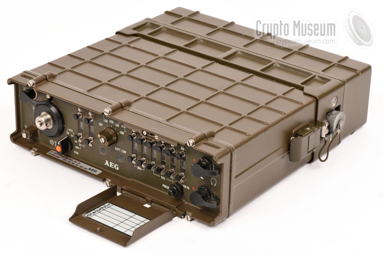
The SE-6861 measures 315 x 300 x 92 mm and weighs 8.5 kg (batteries included).
It consists of two parts:
the actual transceiver
and a removable battery pack, which its mounted
at its bottom. It was usually supplied in a
green carrying case
that also had space for some of the accessories.
Except for the battery charge socket, all controls and
connections are located at the front panel, with the frequency setting
buttons protected by a hinged lid. It covers the entire 1.5 to 30 MHz
frequency band in 100 Hz steps and offers an output power of
2 or 20 Watts, in LSB
or USB.
|
|
|
|
The transceiver was suitable for a 30 to 1500 km operational range and was
the standard radio set of many Special Forces (SF) world-wide during the
1980s en 1990s, such as with the German Fernspäher and the Dutch Commandos.
In The Netherlands it was known as LAPR, which is short for Lange Afstand
Ploeg Radio (Long Distance Group Radio). The radio was in production until
at least 1989, and was replaced in the
late 1990s by modern Harris radio sets,
and later by SDR.
|
SE-6861/11 Initial version, SSB (without LSB/USB selection) - Basic version with ATU, no remote control
SE-6861/22 Basic version without ATU, no remote control SE-6861/32 Basic version with ATU, remote controllable SE-6861/42 Basic version without ATU, remote controllable E-6862/02 Receiver-only version SE-6863 100W version, with external PA and ATU
|
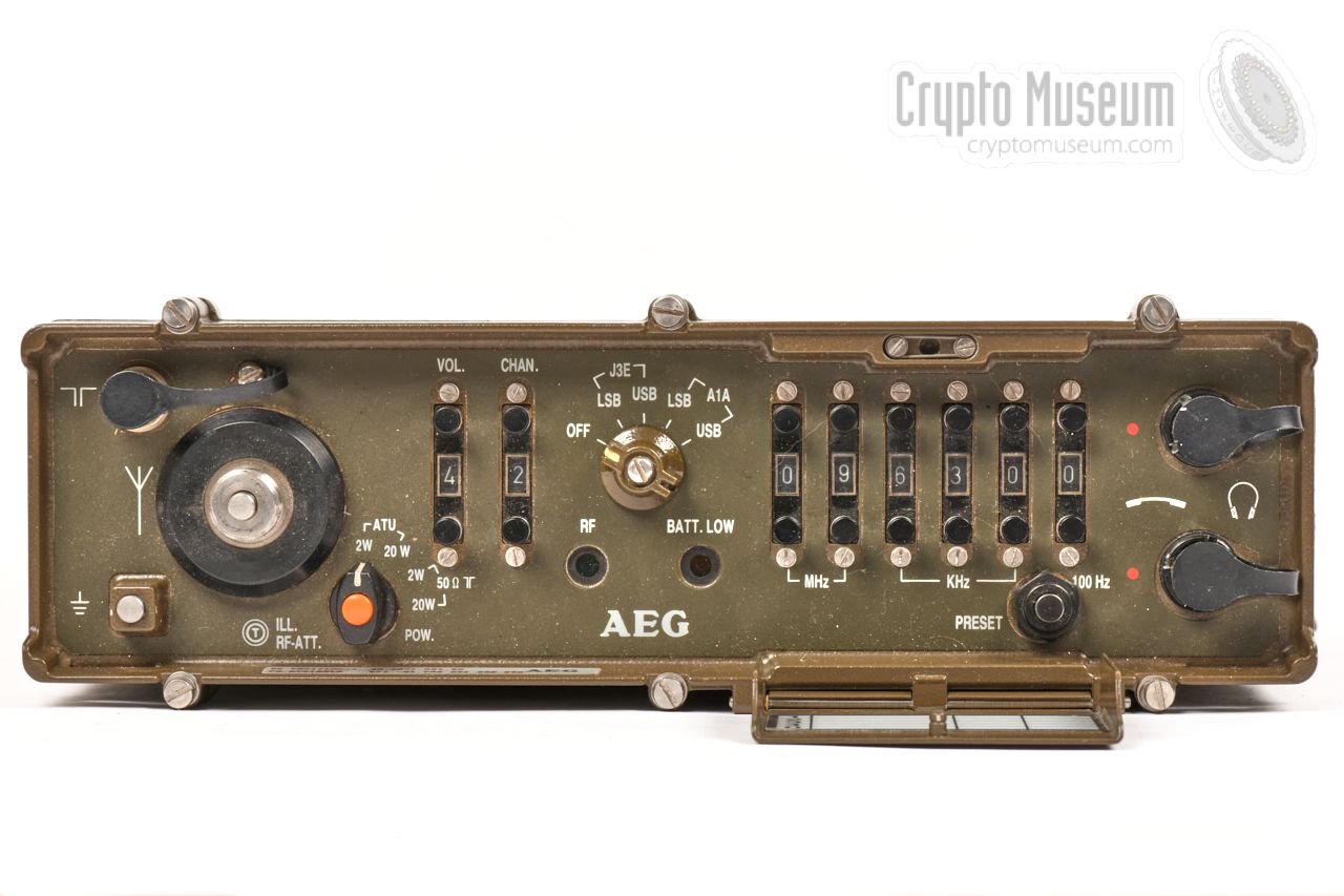
Operation of the SE-6861 is really straightforward. The MODE-selector at the
top center is used to turn the set ON and OFF and to select the desired MODE
of operation. The user can select between USB
and LSB, and between voice (J3E)
and CW (A1A). Another selector, at the bottom left, is used to select the
appropriate antenna (rod, wire or external) and the desired RF output power
(2W or 20W). The built-in antenna tuner is used in combination with a
rod or a wire antenna.
The current frequency can be set with a series of UP/DOWN push-buttons
at the right, in steps of 100 Hz. Another UP/DOWN selector, to the left
of the MODE selector, can be used to select one of four memory channels.
Setting this selector to 0 (zero) selects the current frequency. Any of
the other memory locations can be programmed, using the PRESET button
at the bottom right.
A suitable handset
or headset can be connection to any of the two sockets
at the right. These sockets can also be used for the connection of a
message unit or a crypto device. An external antenna can be connected to
the BNC socket at the top left. When operating the radio in the dark,
the orange push button at the center of the ANTENNA/POWER selector can
be used to turn on scale illumination.
Audio volume can be set in 7 steps using another set of UP/DOWN buttons.
|
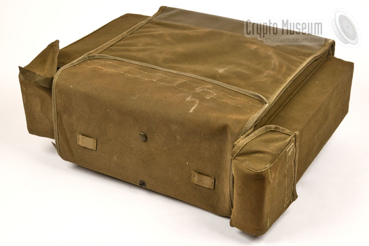
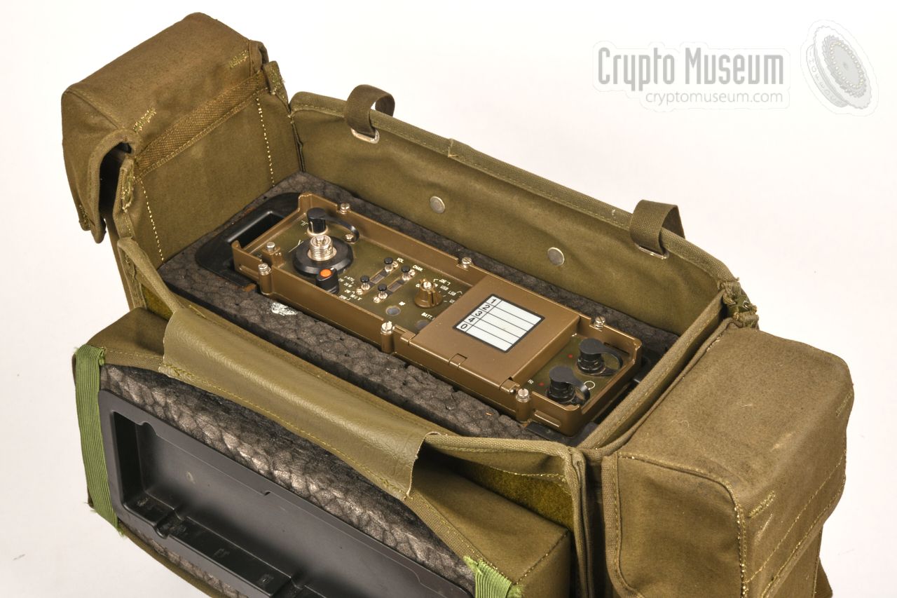
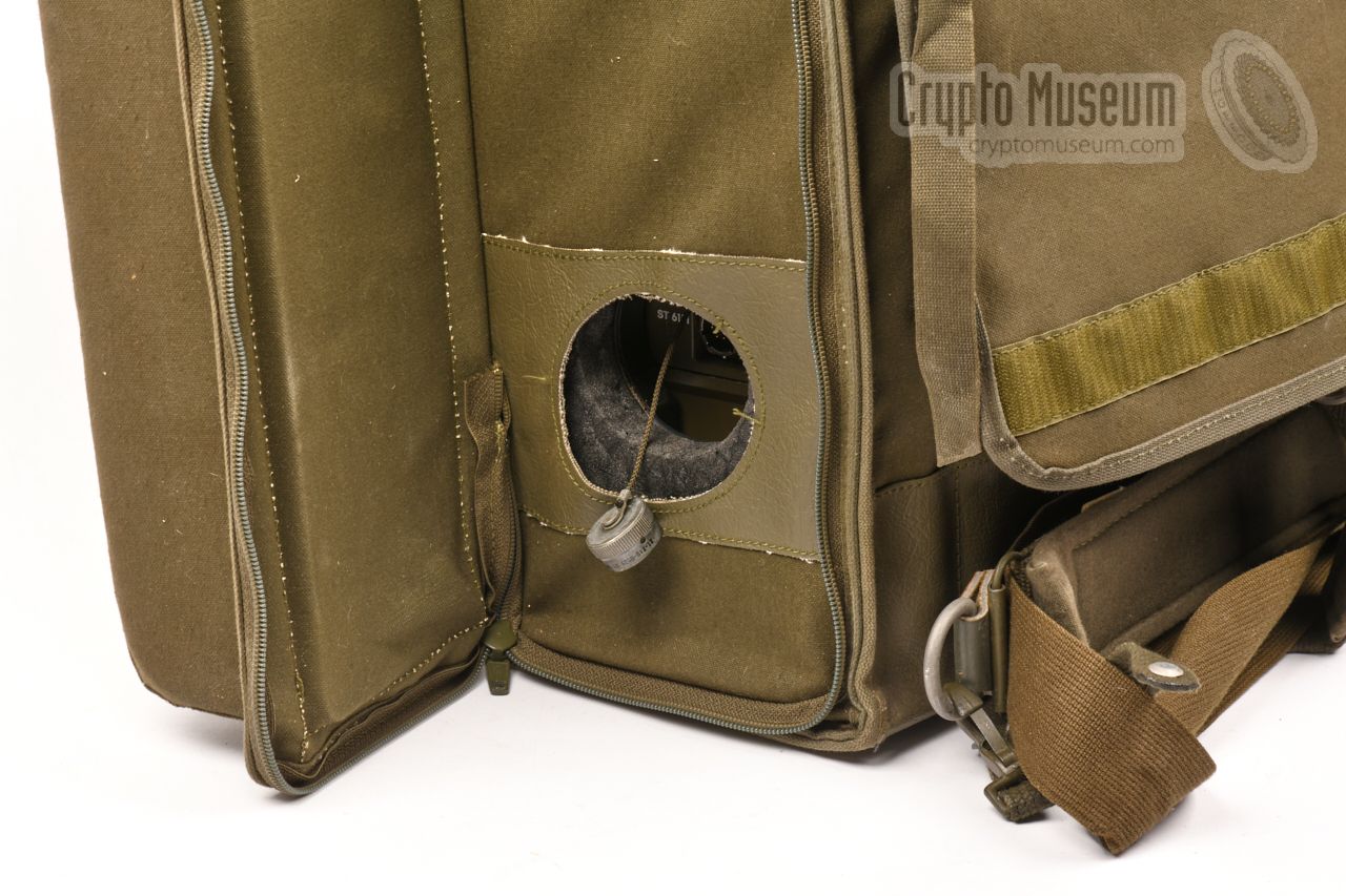
The radio was commonly supplied in a green watertight storage case
that could be carried on the back. In order to reduce weight, the
internal frame that protects the radio against
severe shocks, is made of lightweight foam.
The case has two narrow pockets at the sides – one for the handset
and one for a multi-section atenna
– and a wide one that can hold cables and documentation.
|
|
|
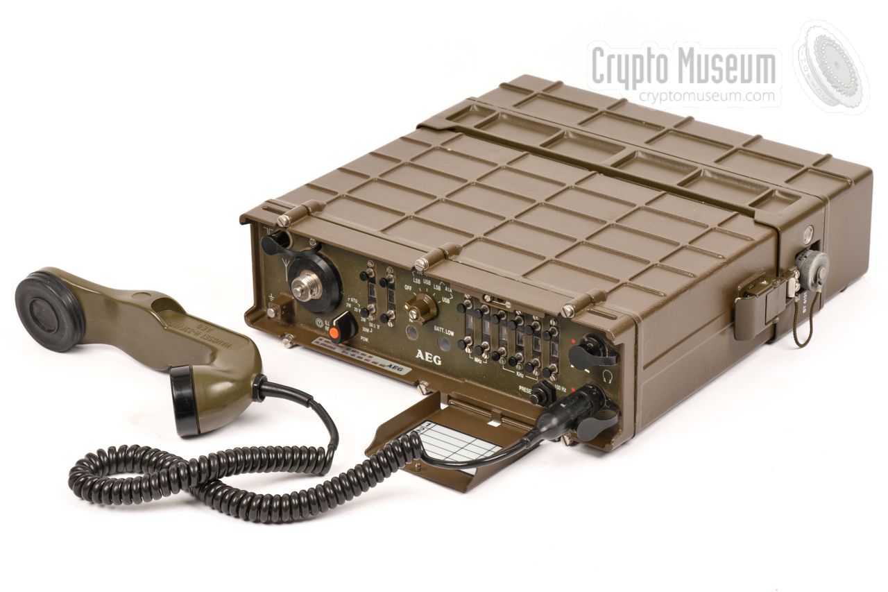
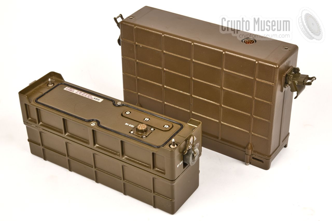
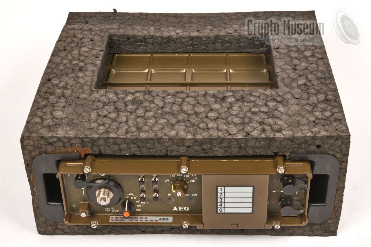
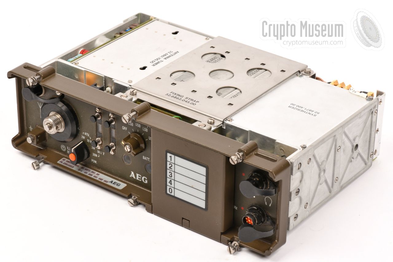
The image on the right shows the actual radio, with the
standard rechargable battery pack installed at the bottom, held together
by two spring-loaded clamps. The power socket is located just below the
rightmost clamp.
The front panel is shown here with the hinged cover – that protects
the frequency setting push buttons – open. At the right are two sockets
for the connection of headset,
handset
and EMU.
|
|
|
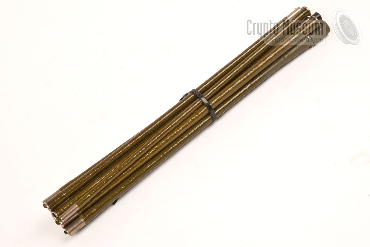
The radio has two terminals for the connection of an antenna.
An external one can be connected to the 50 Ohms BNC socket at
the front panel, whilst a local one can be installed on the large
screw terminal just below the BNC socket.
Several types of antenna were available for the SE-6861, such as
the multi-section foldable one shown in the image on the right.
When unused, it can be stowed in a pocket of the carrying case.
|
|
|
In most cases, the SE-6861 was used with the common handset shown in the
image on the right. it has a standard plug – NF07 in this case –
for connection to the radio.
Note that some international versions of the SE-6861 had different audio
connectors.
|
|
|
Although a purpose built headset was available for the SE-6861,
many users preferred the Racal one shown in the image on the right,
because of the better audio quality.
In this case, the Racal headset is wired with an NF-07 plug, that
can be connected directly to one of the audio sockets at the
right side of the front panel.
|
|
|
The SE-6861 is usually powered by a 30V battery pack that is attached at the
bottom of the radio. Different types of battery used to be available.
When installed, the battery connects directly to the radio. Furthermore it has
a power socket at the right side, through which the radio can be powered and the
battery can be charged. This socket accepts a 19 to 38V DC input. It takes
approx. 14 hours to charge the batteries.
|
|
|
The cable shown in the image on the right was used for charging the batteries,
by connecting it to a 19 to 38V DC power source. The charging current should
be approx. 200 mA.
Other cables were available for connection of an
Electronic Message Unit (EMU)
and for external power souces, such as the battery of a vehicle.
|
|
|
|
|
Electronic Message Unit
EMU
|
|
|
|
|
Digital Message Device
DMD, MEROD, TDED
|
|
|
In the UK and in The Netherlands, the SE-6861 was often used with a
Racal
Message Entry and Read-Out Device (MEROD), such as the
MA4248,
the MA4450
and the
MA4480.
For the US Army, Racal developed a special version of the MEROD,
that was known as the KY-879/P.
The image on the right shows a typical Racal MEROD unit —
the MA-4450 —
with was used in combination with a variety of military radio sets,
including the SE-6861.
It is shown here in its protective nylon carrying bag with the optional
illumination lid installed and opened.
The bag has several pockets for holding the various cables, accessories
and a junction box. They can be packed in such a way that the entire unit
is ready for use at any time. For a long time, MEROD devices were standard
issue with Special Forces (SF) in many countries.
➤ More information
|
|
|
|
In the Netherlands, the SE-6861 was introduced in the early 1980s,
with the Special Forces (104 Waarnemings- en Verkenningscompagnie).
It was called LAPR, which is short for Lange Afstand Ploeg Radio
(Long Distance Group Radio) and was given the internal designator KL/TRC-5151.
|
The SE-6861 was used in combination with a Racal MEROD crypto unit,
either the
MA-4248,
the MA-4450
or the
MA-4480
which was given the designator KY-55590/TGC-5551.
The common Dutch name for it was DBA, or Digitaal Berichten Apparaat
{Digital Messaging Device).
The SF 104 used this rig to operate from behind enemy lines, after infiltration
during the night or after having been dropped as a parachutist. They would hide
themselves underground and operate from there.
They often used inconspicious NVIS wire antennas, such as the well-known WINDOM.
|
|
|
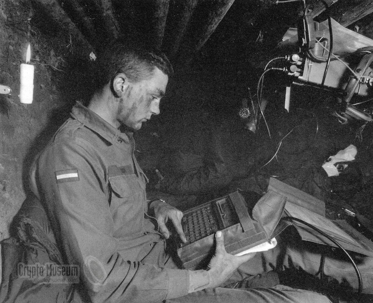
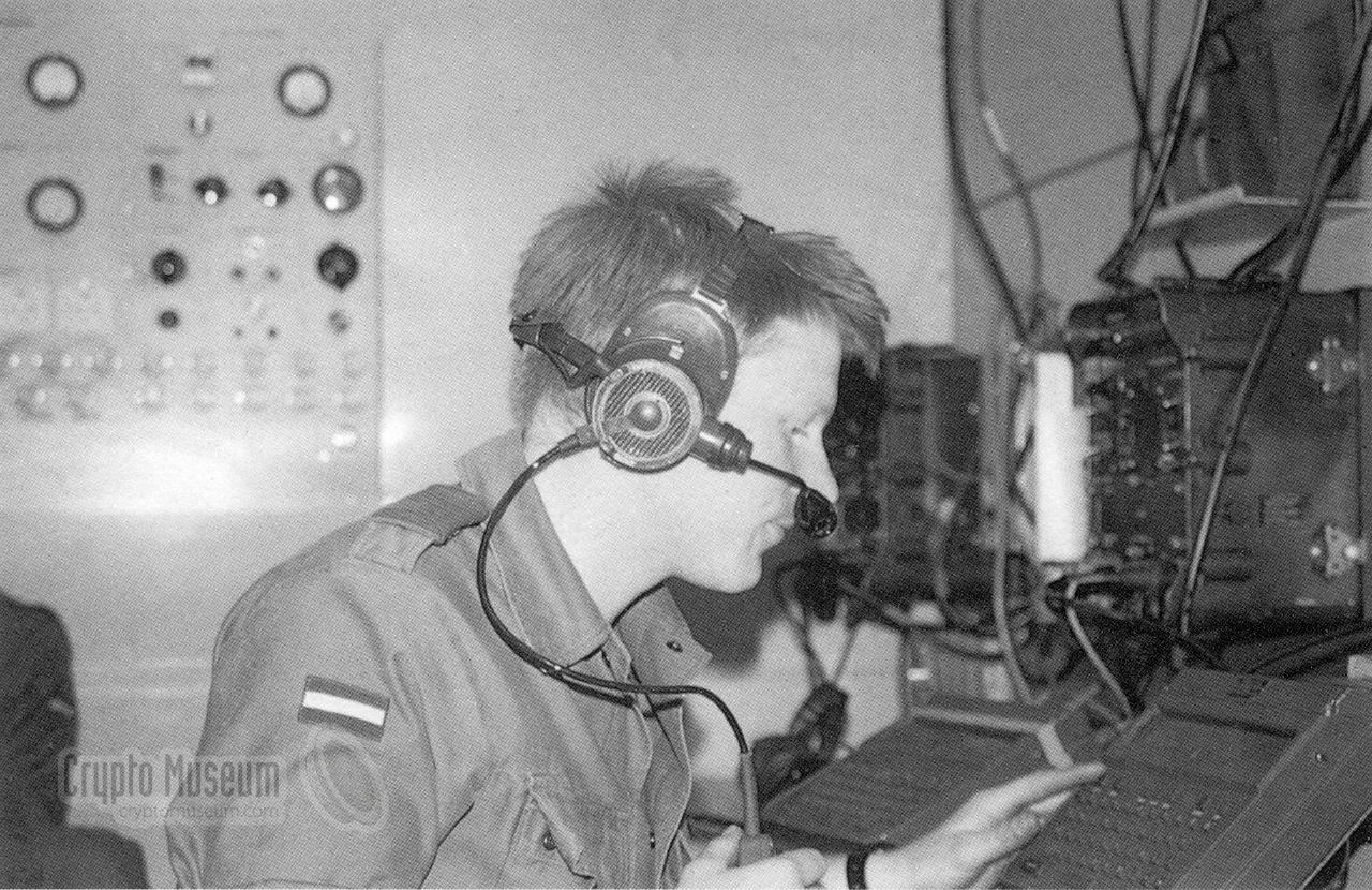
The image above shows a Dutch Special Forces soldier in an underground hideout [1].
The soldier in the picture is entering a message on his MEROD device (DBA).
The SE-6861 (LAPR) is visible in the top right.
Note that the version used by the Dutch,
has U-299 connectors rather than NF07.
|
Messages were first converted into a series of short messages –
typically with a manual system like
Slidex or
Batco – and
were then encrypted and transmitted in AFSK by means of MEROD.
The radio was operated in an acurate time and frequency scheme, which was very
difficult to predict for an outsider. As a result, the radio station was very
dificult to intercept and locate.
All messages were monitored and recorded in
a central listening post comprising a few radios, a PC and
Racal's Message
Base Station MA-4420.
|
|
|
|
In the Netherlands, the MA-4420 base station was known as
KY-5589/TGC-5578. Messages could be printed onto paper,
for further handling by intelligence officers (INTEL).
The photograph above shows the same MEROD device (DBA)
in use in a Dutch command center
[1].
In the early 2000s, the Dutch Special Forces dropped the SE-6861
in favour of
Harris radio equipment.
|
|
The SE-6861 is housed in a strong lightweight die-cast aluminium enclosure,
that consists of a front panel and a case shell. The two parts are held
together by six screws around the edges of the front panel. All internal
parts are mounted into a frame that is attached to the front panel.
|
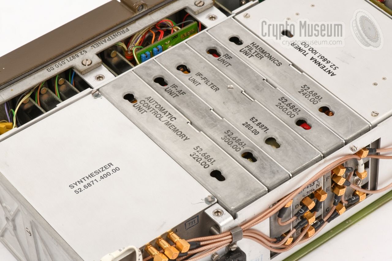
After loosening the six bolt at the edges of the front panel, the entire
contents of the device
can be extracted from the case shell, as shown here.
The olive green front panel is facing away here.
The device comprises a
large motherboard at the bottom,
into which a number
of modules
are plugged. Some of these modules (in particular the synthesizer
and the RF power amplifier) are part of the construction. At the top center
is a removable stainless steel bracket with five holes,
that serves as an extractor for the modules.
It can be slotted into the top
of each module.
|
|
|
|
Note that some modules are not only interconnected via the motherboard,
but also at the rear, by means of a series of teflon coaxial cables with SMB
connectors. They should be unplugged before removing a module. Also at the
rear is a 10-pin power socket
for connection to the battery pack.
|
Note that the pinout of this connector is quite different from the (identical)
power socket at the side of the battery pack. It should not be used to power
the radio directly. Instead, power should always be applied via the
battery pack socket.
Most modules – with the exception of the power amplifier (PA) and the front
panel – are housed in an aluminium can, with a removable lid that is held in
place by four sealed screws. Inside each can is one or more printed circuit board (PCB). As an example we are showing the two PCBs of the memory module
in the image on the right.
|
|
|
|
According to date codes on the various components, the device shown here was
manufactured in the late 1980s, probably in 1989, although most parts were
made five years earlier, in 1984.
As most SE-6861 units are now well over 30 years old, it seems
logical to assume that the batteries will now be exhausted and can
no longer be charged. Luckily,
the battery pack is fully acessible and various initiatives on the internet
demonstrate how the batteries can best be replaced [2].
|
|
The SE-6861 has two identically wired audio sockets at the right hand side
of the front panel. On the standard (German) version of the radio,
these sockets are of the NF07 type, and are wired for standard German handsets.
Here is the pinout when looking into one of the receptacles:
|
- Audio out 0dBm/600Ω
- Speaker
- Microphone (1)
- PTT (or morse key)
- connected to 'E' on other socket
- Microphone (2)
- Ground
|
|
|
One some international versions of the SE-6861, such as the ones used by
the Dutch Special Forces, the NF7 audio sockets were replaced by
U-229 sockets,
which was the common standard within the US Armed Forces
and NATO. Below is the pinout when looking into the receptacle.
|
- GND
- Speaker
- PTT
- MIC
- not connected
|
|
|
Below is the pinout of the power socket on the right side of the battery
pack, when looking into the socket. Note that this connection can be used
to power the radio directly (by using pin D/E), or to charge the battery
(using pin C/J), whith the (-) terminal always connected to A/B/H.
|
- GND
- GND
- Charge (+) 21.5 — 32V
- External supply (+) 21.5 — 38V
- External supply (+) 21.5 — 38V
- Battery charger (+)
- Over-temperature protection
- GND
- Charge (+) 21.5 — 32V
- Battery charger (+)
|
|
Device Portable manpack MW/SW two-way radio Purpose Long distance military and special forces voice and data communication Model SE-6861/12 mod ➤ More Year 1972 ~ Manufacturer AEG Telefunken Frequency 1.5 - 30 MHz in 100Hz steps Output 2W or 20W PEP ATU Built-in Antenna Tuning Unit ASG-6861 Modulation J3E (SSB) in LSB or USB, A1A (CW) and (optionally) FSK Channels 4 + 1 IF1 40.090 MHz IF2 9.910 MHz Power 19 - 38V DC Battery 30V, 1/8 Ah Temperature -35°C to +55°C Dimensions 315 x 300 x 92 mm Weight 8.5 kg (including battery)
|
LG-6874/1 Battery charger LG-6864/11 Battery charger KG-6864/1 Hand generator BT-6861/11 Battery NiCd 30V, 1.8 Ah (rechargeable) BT-6861/21 Battery NiCd 30V, 4 Ah (rechargeable) BT-6861/31 Battery Li/Mn 39.2V, 10 Ah (non-chargeable) FH-6864 Vehicle mount FH-6865/24 Vehicle Mount 24V LA-6861 Long-wire antenna A-6864 Vertical 3.3 metre rod antenna (whip, multi-section, foldable) SV-6863 100 W Transmitter Amplifier BG-6861/1 Remote control unit
|
|
|
|
Any links shown in red are currently unavailable.
If you like the information on this website, why not make a donation?
© Crypto Museum. Created: Friday 27 January 2012. Last changed: Wednesday, 05 November 2025 - 12:03 CET.
|
 |

|
|
|