|
|
|
|
|

|
|
USA Radio Crypto FILL
Audio, Data and FILL connector
U-229 is a standard military connector used by the
US Armed Forces and NATO for connection of audio equipment
(microphone, headset, handset, etc.) to a radio, as well as for the connection
of key loaders (FILL)
to cryptographic equipment.
The standard connector has 5 pins, marked A-E, but a 6-pin version also exists.
It has an extra pin – marked 'F' – which is located at the center.
The image above shows the pinout when looking at the contacts of the
female receptacle (left) and male receptacle (right).
Many different versions of the connector and its mating cable parts exist,
such as 5- and 6-pin variants, male or female and cable or panel mount.
Although each variant has its own specific type number, they are commonly
incorrectly referred
to as U-229. The table below shows the correct nomenclature.
U-229/U is the 5-pin female cable mount part.
|
| Type | P/S | Pins | Shape | Description |
|
|
| U-228/U | P | 5 | ◍ | 5-pin, male, cable mount |
| U-229/U | S | 5 | ◍ | 5-pin, female, cable mount |
| U-328/U | P | 6 | ◍ | 6-pin, male, cable mount |
| U-329/U | S | 6 | ◍ | 6-pin, female, cable mount |
| U-183/U | P | 5 | ◍ | 5-pin, male, panel mount (chassis) |
| U-283/U | P | 6 | ◍ | 6-pin, male, panel mount (chassis) |
| GC-429 | S | 5 | ◍ | 5-pin, female, circular panel mount (chassis) |
| GC-629 | S | 5 | ▢ | 5-pin, female, square panel mount (chassis) |
| GC-529 | S | 6 | ◍ | 6-pin, female, circular panel mount (chassis) |
| GC-729 | S | 6 | ▢ | 6-pin, female, square panel mount (chassis) |
|
P = Plug (Male), S = Socket (Female)
|
|
U-229 connectors are used for the following applications:
|
|
The U-229 was initially designed for use as an audio connector on military
radio equipment. The female cable part is commonly found on microphones,
speakers and handsets. In most cases the 5-pin version is used for this.
The radio itself usually has a 5-pin U-183/U male receptacle.
|
The image on the right shows a typical U-229/U female connector (right) as
part of a handset. On the left is the radio set which (in this case) has two
identical U-183/U receptacles. This is done to allow simultaneous
connection of microphone and speaker. The NATO-standard
pinout of this connector is given below.
Note that microphone and speaker levels may vary between radios.
Some radios, such as the SINCGARS RT-1439,
are fitted with 6-pin receptacles (U-283/U), in which case the extra contact
(F) may carry an extra signal or power for a peripheral device.
|
|
|
|
All radios used by the US Armed Forces and NATO, with very few exceptions,
have the same wiring layout of the AUDIO connector. This improves
compatibility between radios and peripherals.
The only known exception, is the Philips RT-3600,
which has two lines swapped (see below).
|
|
The US/NATO standard defines pins A-D only. Pins E and F are optional
and not standardized.
|
| Pin | NATO | Description | Note |
|
|
| A | GND | Ground (common wire) | |
| B | SPK | Speaker | 1 |
| C | PTT | Push-to-Talk switch (connects to ground) | 2 |
| D | MIC | Microphone | |
| E | EXP | Various expansions. Power in/out. Not standardized. | 3 |
| F | EXT | Extra signal or power out. Not present on most radios. | 4 |
|
 |
-
Some radios have a +6V DC offset on this pin. It is used for sensing the
presence of an external speaker and (if it finds one) muting the internal
speaker.
-
This pin should be grounded when transmitting. It is neither an input nor an
output, but a BUS. Anyone on the bus can start a transmission by asserting
this line to ground. On some radios it is also used for CW
(morse), but this is not possible if the
radio supports SSB. In that case, pin E is used for CW.
-
The function of pin E is not standardized.
Different radios used it for different purposes.
On some radios, such as the PRC-68 family, it is used as a 12V power input.
Manpack radios, like PRC-74 and PRC-104 may use it for CW
(morse).
In such cases it can also be used for the connection of a high speed
burst encoder
like the GRA-71.
Other possible uses for this pin are extra speaker and retransmission
{repeater).
-
Pin F is not present on the original U-229 connector. On some radios
the extra pin is reserved for future modifications or additional features.
Some radios use it for digital signals (e.g. uploading and
downloading of channel frequency assignments) or retransmission PTT.
It may also be used to supply power to a peripheral.
|
|
As far as we know, the only exception to the above standard is the
RT-3600 radio, manufactured by
Philips in The Netherlands. For some reason,
the microphone (MIC) and speaker (SPK) lines are swapped.
Handsets and headsets were wired
accordingly. Confusingly, Philips corrected this on later equipment,
such as RT-4600
and Spendex 10, but the
RT-3600 was never modified.
This means that two types of handset wiring can be found in The Netherlands.
It is easy though to swap lines B and D, either in the handset, or its
U-229 connector, or (better) inside the radio.
|
| Pin | RT-3600 | Description | Note |
|
|
| A | GND | Ground (common wire) | |
| B | MIC | Microphone | |
| C | PTT | Push-to-Talk switch (connects to ground) | |
| D | SPK | Speaker | |
| E | - | Unused | |
| F | - | Unused | |
|
|
|
FILL
crypto, frequency hopping
|
|
|
|
The 5 or 6-pin version of the U-229 can also be used for connection
of a key loader to a crypto device,
or to a radio with built-in crypto and/or
frequency hopping (FH) capability.
In some cases, such as with the SINCGARS
radios, this is combined with the AUDIO or DATA socket.
If a 6-pin receptacle is present (U-329/U), the extra pin (F) may carry
power, but this is not mandatory.
|
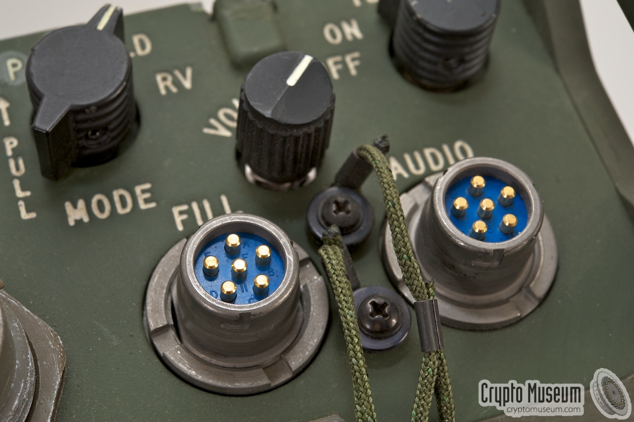
The image on the right shows two 6-pin U-283 receptacles on the front panel
of the KY-57 voice encryptor. The rightmost one is
for the handset. The leftmost one is for loading cryptographic
keys into the device by means of a key filler.
For manufacturers it is mandatory to design radios and preripheral
equipment with U-229 connectors, in such a way that nothing will be damaged
when peripherals are connected to the wrong connector. This is necessary,
as the same connector is used for AUDIO, DATA and FILL purposes,
and a mistake is easily made.
|
|
|
|
Generally speaking, there are two different protocols for transferring
cryptographic keys from a fill gun into a radio or crypto device.
They are both endorsed by the NSA. The oldest standard is
DS-102, which features synchronous data transfer
at arbitrary speeds. Examples are KOI-18 and KYK-13.
DS-102 has gradually been replaced by the newer
DS-101 standard, which is based on RS-232.
In practice, most modern devices support both standards through the same
connector.
|
|
This is the oldest protocol used for KEY FILL devices. It describes the
physical specifications as well as the data flow. In the early 2000s, the
DS-102 protocol was freely available on the internet, but has since been
removed. From surviving documents it is known that it is a synchronous
data protocol with negative logic, in which a '0' is represented by 0V
and '1' is represented by -6V. 1
|
| Pin | DS-102 | Description | Note |
|
|
| A | GND | Ground (common wire) 0V | 1 |
| B | SWG | Switched Ground (optional) | 2 |
| C | ACK | FILL request acknowlegment | |
| D | DATA | Fill data into radio or crypto device | |
| E | CLK | Fill clock into radio or crypto device | |
| F | - | - | |
|
The advantage of synchronous data communication is that it can be used at various
speeds (and even at varying speeds) without the need to configure the
receiving device accordingly. This was particularly useful when using the
KOI-18 key tape reader, where the punched paper tape has to be
pulled through the device manually. In that case, the sprocket hole provides
the clock (CLK).
➤ More about the DS-102 protocol
|
-
In some equipment, the FILL interface is completely isolated from the
rest of the circuitry. In that case, the local ground on pin (A) might
be at +5V relative to the equipment chassis. This should be interpreted
as GND on the FILL device. In that case, the equipment chassis (0V)
represents a -5V signal on the FILL device, which should be interpreted
as a logic '1'. NEVER use the chassis (shield) of the connector!
-
Connect the SWG line (B) to GND (A) to signal to the equipment that a FILL
device has been connected.
|
|
This is a later (now current) standard that superceedes the earlier
DS-102.
Like DS-102, it is endorsed by the NSA
and its description is not available in the public domain.
It is a serial asynchronous protocol that runs over an RS485/RS232D
interface, with data input and output lines (RXD/TXD) plus handshaking (CTS/RTS)
and runs at 64 kb/s using the HDLC data protocol.
|
| Pin | DS-101 | Description | Note |
|
|
| A | GND | Ground (common wire) 0V | |
| B | RTS | Request to Send | |
| C | RXD | Data out of radio or crypto device | |
| D | TXD | Fill data into radio or crypto device | |
| E | CTS | Clear to Send | |
| F | - | - | |
|
The advantage of using asynchronous serial communication is that it can
be integrated more easily with applications running on modern computers,
either directly from an RS-232 port (also known as the COM port) of a
Personal Computer (PC)
or via a suitable USB-to-RS232 adapter.
➤ More about the DS-101 protocol
|
|
Earlier SINCGARS radios, such as the RT-1439,
have a FILL socket for programming the
Frequency Hopping (FH)
tables. This was usually done with a specific transfer device like the
MX-18290.
The table below shows the pinout of the FILL
connector as specified in the SINCGARS manual [1].
|
| Pin | SINCGARS | Description | Note |
|
|
| A | GND | Ground (common wire) | |
| B | CCD | Not used for fill | |
| C | FILL REQ-N | Fill request acknowledgment | |
| D | FILL INFO | Fill data into radio | |
| E | FILL IA | Fill info available | |
| F | MUX | MUX Override. Not used for fill | |
|
On non-COMSEC devices,
voice encryption was achieved using an external
voice encryptor, like the KY-57
or KY-99. These devices have a separate FILL connector
for loading the cryptographic keys, which requires a KYK-13
key transfer device, or similar. Later SINCGARS
radios have built-in COMSEC facilities and allow a
KYK-13 (or equivalent)
to be connected directly to the radio.
|
|
The 6-pin version of U-229, known as U-329/U,
is also used for DATA interfaces
on SINCGARS radios. Data can be send as
analog tones between 300 and 3000 Hz (slow speed, e.g. on HF) or as true digital
signals with a variety of baud rates between 75 baud and 16 kbit/s (ASYNC/SYNC).
|
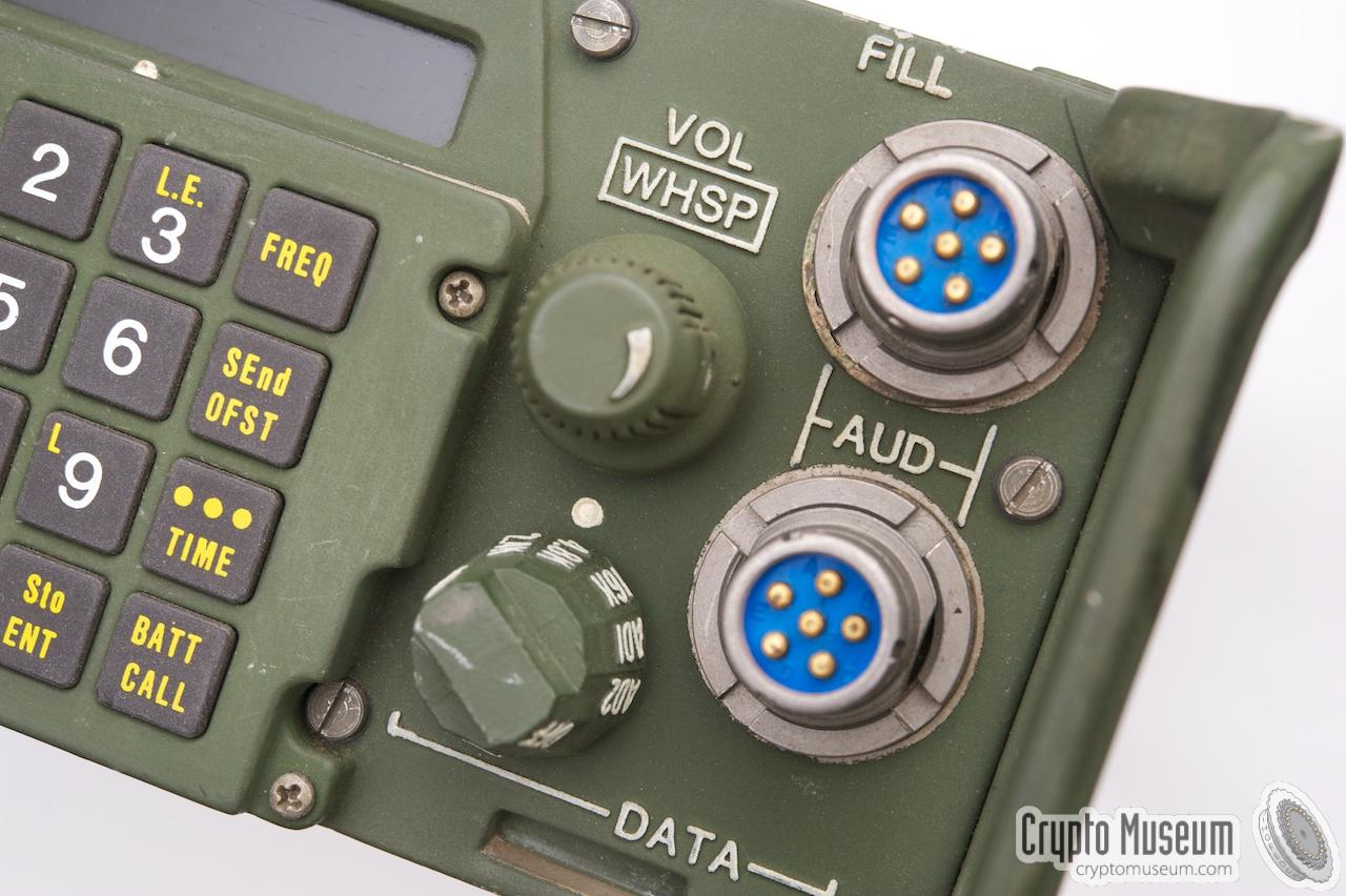
The image on the right shows the RT-1439
SINCGARS radio, which has two identical 6-pin connectors on its front panel.
One connector is marked AUDIO/FILL. The other one is marked AUDIO/DATA.
Although any analog audio device (handset, microphone, speaker, headset)
can be connected to either connector, the digital signals carried by
the data pins are completely different.
The upper connector shares the FILL function and allows a
key fill device to be connected.
The lower connector shares the DATA interface and allows the connection of
a digital serial device.
|
|
|
A rotary switch to the left of the lower AUDIO connector is used for selection of
the appropriate serial speed (baudrate). It can be set to a number of speeds between
75 and 4800 baud (4K8) in asychronous mode, or 16000 baud (16K) in synchronous mode.
When in synchronous mode, one of the pins of the connector carries the clock signal
(CLK). The table below shows the pinout of the connector in DATA mode.
|
| Pin | SINCGARS | Description | Note |
|
|
| A | GND | Ground (common wire) | |
| B | RXD | Data from radio | |
| C | PTT | Grounded when transmitting | |
| D | CLK | Clock out (in synchronous mode) or TXD (analogue) | 1 |
| E | DIG | Digital Data Mode Select (when grounded) | 2 |
| F | TXD | Data into radio | 3 |
|
-
In Analog mode, this pin is used as input for the data tones.
Analog mode is selected by grounding pin F.
This probably bypasses any filtering in the audio path of the transceiver.
In synchronous digital data mode, this pin carries the clock signal (CLK).
-
The excact functionality of this pin is currently unknown.
Grounding this pin seems to select digital (data) mode.
When both pin E and F are high-impedance (default) analog voice mode is selected.
-
In digital mode, this pin is used as the DATA input (into the radio).
When pin F is grounded, analog data mode (i.e. tones) is selected.
|
|
|
|
Any links shown in red are currently unavailable.
If you like the information on this website, why not make a donation?
© Crypto Museum. Created: Tuesday 20 December 2011. Last changed: Monday, 10 June 2024 - 18:38 CET.
|
|

|
|
|
|
|
|
|
| | |