|
|
|
|
|

|
|
RX DF RCD TAIYO PAN-3000 → ← PAN-1000
The complete system is about the same size as its predecessor
— PAN-1000 —
and was usually mounted in the trunk of a regular car,
with the controls and displays mounted at a convenient position near
the driver seat.
The PAN-2000 was introduced in 1995 and gradually replaced
the existing PAN-1000 systems
over the course of the following years.
In total, ~ 20 systems were built. Between 2005 and 2007 they
were gradually replaced by their successor, the
PAN-3000.
➤ History of the PAN-2000
|
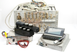
The diagram below shows the setup of a complete PAN-2000 system.
At the bottom is the ICOM IC-R9000 communications receiver,
that has several links to the
ELCOM FFT Processor just above it. They form the heart of the
PAN-2000 system. The FFT Processor is fed by the IF output of the receiver,
from which it creates the spectrum display. At the right is the CONSOLE
that is located between the front seats of the car. It is modelled
after the remote control unit of the PAN-1000.
To the left of the FFT Processor is the
TAIYO direction finder,
which is basically a stand-alone system connected to the IF output
of the receiver. It controls the 4-segment flat antenna
that is hidden in the car's sunroof, and drives the
compass display at the left. The switch box and
the RF pre-amplifier are integrated with the antenna. At the top right is
a stand-alone frequency counter with built-in field-strength indicator
that instantly shows the frequency of any nearby signal. It is connected
to the console, allowing the receiver to automatically tune to the displayed
frequency.
}
|
In a mobile environment the entire system must be powered by the 12V DC
voltage of the car battery. The 12V from the battery should be applied to
the 19" rackmount FFT Processor, which acts as a central hub. From there
the other items are powered. The console is used as a remote control unit.
The diagram below shows how the various PAN-2000 modules are powered [3].
At the top left is the raw 12V DC voltage from the regular car battery.
It is passed to the Console which switches and distributes it to the other
peripherals and to the switch input (start) of the FFT Processor.
Inside this unit is a solid state relay that controls the internal
DC/DC converters and hence the 12V and 15V supply to the TAIYO
direction finder and the ICOM receiver respectively. The TAIYO TD-L1706 main
unit provides the +5V and +9V voltages for its display and antenna.
A separate 12V battery was used for powering the FFT Processor, the ICOM
receiver and the TAIYO direction finder, as they could potentially exhaust
the main car battery when the vehicle is not running. By using a separate
battery (that is charged together with the regular battery), it remains
possible to start the car, even when the 2nd battery is flat. Another
advantage of this approach is that the equipment does not suffer from
a voltage drop when the car is started.
|
Unlike the earlier PAN-1000 system
— which ad been designed completely from
scratch — the PAN-2000 was built around an existing
ICOM IC-R9000 communications receiver.
This was done to reduce development time, but also to reduce the
cost of a complete system.
The ICOM receiver was modified
at several points, mainly to reduce
spurious signals and to make the connections at the rear more robust.
➤ More information
|
|
|
|
At the heart of the system is the FFT Processor that was developed especially
for the Dutch Radio Monitoring Service
by ELCOM GmbH. It takes
the IF signal from the ICOM receiver and converts it into a frequency
spectrum display,
using hardware-based Fast Fourier Transform (FFT) functions.
|
The FFT processor is also responsible for the user interface (UI).
It takes the input from the console, and delivers a visual
output on the wide-screen EL display described below.
In order to reduce the interference caused by the system itself,
all communication between the FFT processor, the display and the console, is
via optical wiring. This has the added advantage that the controls can
be placed further from the processor. In practice, the FFT processor
was mounted in the trunk of the car, with the console and the display near the
dashboard of the car.
|
|
|
|
The FFT processor can be powered either from the AC mains, or from a 12V DC
source like the battery of a car. In practice it was usually powered from
a mains voltage, even when used in a mobile invironment, using a power inverter.
A more detailed description can be found below.
|
|
The output of the FFT Processor is passed by the VIDEO card,
to a flat-panel electroluminescent (EL) display with a
resolution of 512 x 256 pixels, which was state-of-the-art in 1995.
The left half of the screen
is used for displaying parameters. The right half holds the
spectrum display.
|
At the rear, the display has threaded holes, to allow it to be mounted on
– or close to – the dashboard. It is powered by 12V DC supplied by the console,
and is connected to the main FFT Processor via four optical wires; one
for each signal: luminance (VID), vertical synchronisation (VS),
horizontal sync (HS) and pixel clock (CLK).
At the time of the development of the system, video monitors were virtually
always based on a cathode-ray tube (CRT), and electroluminescent displays
(EL) were the only ones that were flat enough for mounting on a
vehicle dashboard.
|
|
|
A major challenge with this display (or any other display for that matter)
was that it had to be bright enough for use in direct sunlight, and yet
dimmable enough to allow its use at night without attracting attention.
For this reason, the display has a luminance adjustment knob at the left side.
For use in bright sunlight, a hood was somethimes mounted in front of the
display.
Displays of this type typically produce a lot of unwanted radio interference
(RFI) that can be picked up by the receiver. As this is undesired
– particularly in this application –
it was decided to place a metal coated glass in front of the display.
A thin metal grid in front of the display was also tried, but appeared to
take away too much light and caused unwanted moiré patterns [9].
|
|
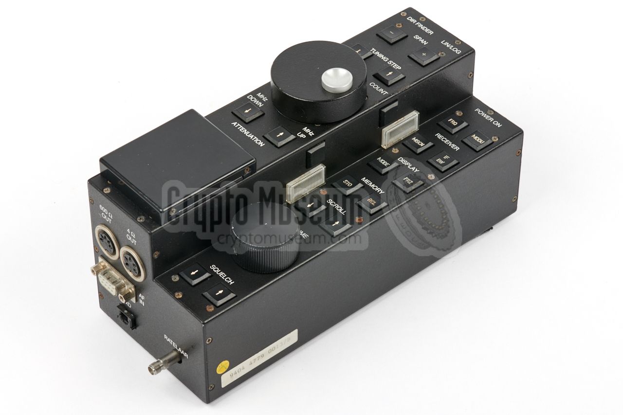
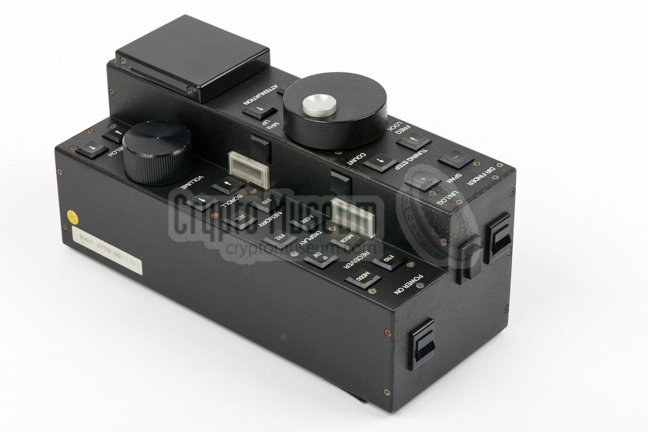
One of the most important parts of the PAN-2000 system is the remote
control unit (RCU) or console. As it had to be operated by the
investigating officer whilst driving the car, its functions had to be
intuitive, so that he or she could find each button quickly without looking
down on it.
|
The image on the right shows the console of the PAN-2000 which is clearly modelled
after the RCU of the earlier PAN-1000 system.
The unit was fitted in between the two
front seats of the car, aside the handbrake, so that it was within reach of the
operator's right hand.
The RCU has only two large rotary knobs: one for tuning the frequency,
and one of adjusting the volume. All other functions are controlled by
push-buttons.
The higher part has two built-in lamps that illuminate the push-buttons on
the right half, so that they can be found more easily in the dark.
|
|
|
The rectangular black hand-rest – at the left rear – is in fact a small hinged
lid below which a numeric keypad is hidden. This keypad can be used to select
memory positions and for entering a frequency directly. At the front side are
the main ON/OFF switch, an ON/OFF switch for the radio direction finder,
and a push-button to select between logarithmic or linear signal-strengh
scale.
All connections of the RCU are at its rear side. There are two DIN sockets:
one for a speaker and one (with a fixed output level) for a recording device.
A female DB9 socket carries the incoming and outgoing 12V power lines, plus the
audio signal from the ICOM IC-R9000 receiver. The RCU is connected to the
FFT Processor by means of a TOSLINK optical fiber link, just like the
display, to eliminate any radio interference on the intercepted
RF signal, caused by the equipment itself.
|
|
|
TAIYO direction finder
TD-L1706
|
|
|
Although the PAN-2000 system can be used without it, the TAIYO TD-L1706
direction finder can make the job of locating a transmitter a lot easier.
It uses a special antenna and takes the IF-output from the IC-R9000,
from which it calculates the angle of incidence of the signal.
➤ More information
|
|
|
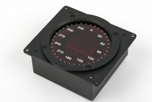
The output from the TAIYO TD-L1706 direction finder is delivered to a
special compass display that can be mounted at a convenient place on the
dashboard of the car. It displays the angle of incidence of the intercepted
radio signal on a 3-digit LED display at the centre of the front panel.
Around the circumference of the display is a circle with 72 red LEDs, one of
which points in the direction of the signal. A switch at the left side can
be used to turn the 3-digit display off.
➤ More information
|
|
|
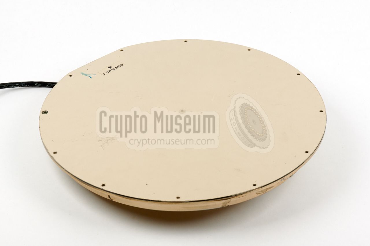
A special flat antenna was used with the TAIYO direction finder.
In consists of four antenna element in a special arrangement, mounted
in the circular enclosure shown on the right.
The antenna was usually mounted in the top roof of the car, disguised
as a sunroof, for which it was modified somewhat. Inside the disc is a
fast antenna switcher and a pre-amplifier.
➤ More information
|
|
|
|
|
Frequency counter
CR-3000/C
|
|
|
|
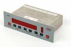
Most intercept vehicles of the Dutch Radio Monitoring Service were also
equipped with a stand-alone frequency counter that could be mounted
anywhere in the car. It had its own antenna and was able onto lock to
any nearby radio signal and display its frequency on the 8-digit display.
|
The 1/100 output of the counter is connected to the RATELAAR input
of the console. When the operator presses the console's COUNT button,
the intercepted frequency – visible on the display of the counter –
is copied to the PAN-2000, which in turn passes it on to the ICOM receiver.
The frequency counter was developed by the Dutch company DARE,
and was also supplied to the Dutch Police for installation in some of their
surveillance vehicles.
➤ More information
|
|
|
The simple antenna selector shown in the image on the right was
used as part of the PAN-2000. It allows various antennas to
be connected to the input of the PAN-2000 (and, hence, the Icom IC-R9000
receiver). The selector was operated by means of a rotary selector
that was mounted near the dashboard of the car.
One of the connected antennas was a simple vertical one
that was mounted on the car. Another one was the directional antenna
used with the TAIYO direction finder.
|
|
|
The audio LINE output from the ICOM IC-R9000 receiver, is supplied
directly to the Console, where it is amplified to speaker level.
A suitable speaker, such as the one shown in the image on the right,
should be connected to the 5-pin 240° DIN socket
at the rear of the console.
The audio volume can be adjusted with a potentiometer on the console.
|
|
|
The Console is used as a direct input for the FFT Processor,
similar to a keyboard of a PC. For this, a dedicated serial port on the
I/O card is used.
To avoid radio interference (RFI), an optical data link is used for this.
The image on the right shows the optical fibre that was used for the
remote connection. It is known as TOSLINK and is commonly available
from audio stores.
|
|
|
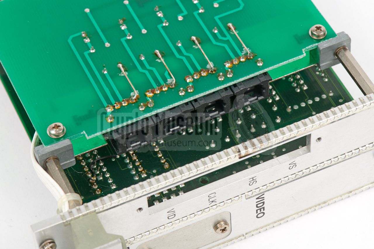
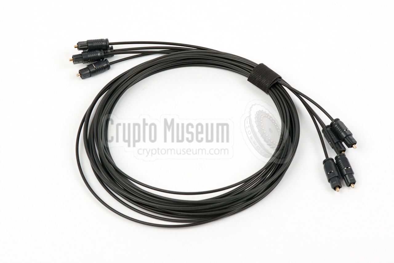
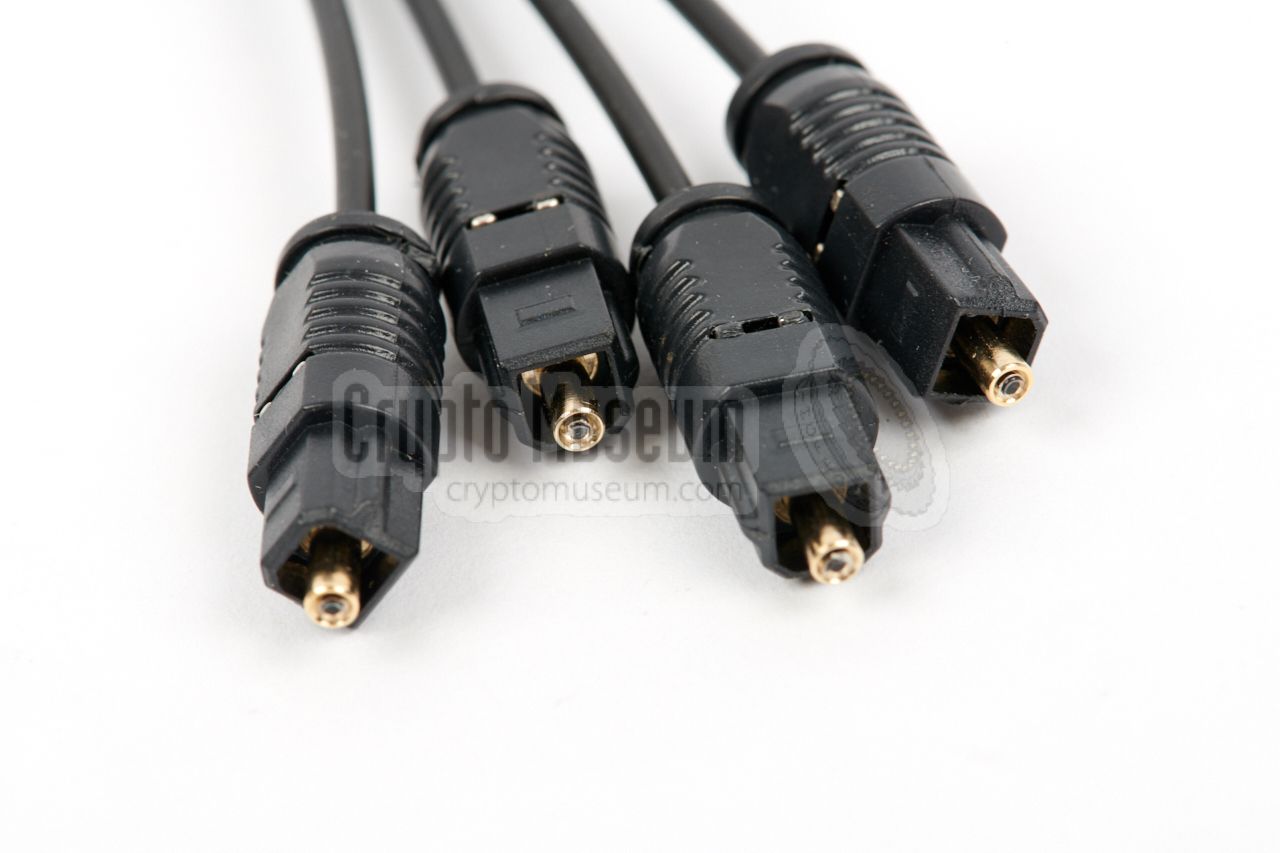
For the same reason (RFI), the video signals from the
graphics card
are passed to the FFT Display via four individual
TOSLINK optical wires.
Note that because of the fact that the TOSLINK sockets on the
video card are recessed, optical wires with narrow plugs
should be used, as otherwise they might not fit.
As an alternative, the video card can be
modified.
|
|
|
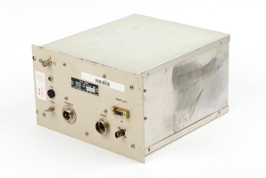
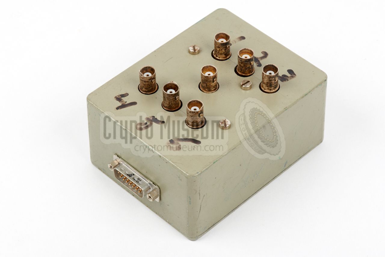
For a complete setup, quite a few power and interconnection
cables are needed. The image on the right shows a breakout box
through which the 12V DC power source should be supplied
to the FFT Processor
and to the Console. The entire system is enabled by
setting the POWER switch at the front of the Console to ON.
This activates a solid-state relay inside the FFT Controller,
which in turn enables all connected peripherals.
The FFT Controller supplies the power for the ICOM IC-R9000 receiver
and for the TAIYO DF unit, for which a separate cable is
required.
|
|
|
|
The following connections are needed:
|
- 12V from battery to breakout box
- 12V from breakout box to PAN-2000 and to Console (via DB9)
- 12V from Console to FFT Display and to Counter
- 12V from FFT Controller to TAIYO DF unit
- 15V from FFT controller to ICOM receiver
- Audio from ICOM receiver to Console (via breakout box)
- TOSLINK wire from Console to FFT Controller
- 4 x TOSLINK wire from FFT controller to FFT Display
- Discriminator output from ICOM receiver to FFT controller 1
- 10.7 MHz output from ICOM receiver to FFT Controller
- Frequency counter (1/100) to Console (Ratelaar)
- 3 x antenna connection from FFT controller to ICOM receiver
- Console speaker output to external speaker
- Antenna to FFT Controller
|
 |
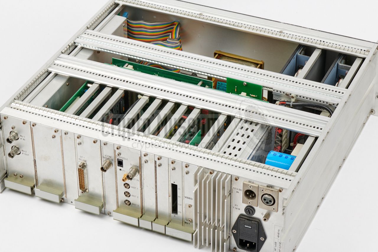
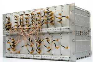
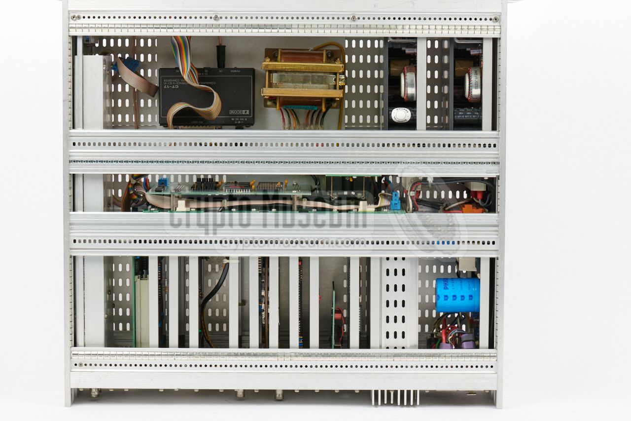
The core part of the PAN-2000 system is the FFT Processor that was
custom-built by ELCOM for the
Dutch Radio Monitoring Service. It is housed
in a 19" 3U rackmount enclosure and consists of several plug-in modules
that can be accessed from the rear side, as shown in this diagram:
In the above diagram, we have identified each plug-in unit with a name.
These names are used in the circuit desciptions below, and also in the
description of the pinouts of the various sockets, further down this page.
The folowing plug-in units and modules are present:
|
|
The FFT Processor is built around an AT96/ISA96 1 bus system, as developed by
IBM in the mid-1980s. It is basically a 16-bit variant of the 8-bit IBM XT-Bus
architecture, intended for industrial applications. Over the years, a wide
range of companies produced plug-in cards for this bus [4].
Note that part of the system is built around the AMS-bus (IEEE 796), which is
different from the AT96/ISA96 bus standard [8]. The two busses are connected
via an ISA96/AMS bridge interface.
|
-
ISA = Industry Standard Architecture.
➤ Wikipedia
|
The diagram below shows how the various modules are connected.
Central to the system is the CPU card with a 16-bit Intel 386 processor (CPU),
that is connected to an ISA96 expansion bus.
This bus has a slot for an (optional)
VGA graphics card (needed for configuration of the system) and an interface
that controls the IF Interface directly above it. The data from the A/D
converter on the IF Interface is passed directly to the FFT processor
via the AMS bus (blue), that is on the other side of the Bridge.
All other peripheral interfaces are also connected to the AMS-bus.
Above the hardware-based FFT processor is the graphics controller
that delivers the image for the FFT display. Above that is the
memory card that holds the firmware (EPROMs) and battery-backed RAM
for storing the frequencies and other settings.
The I/O card controls the antenna relay and the attenuator.
It also hold the optical interface to the Console.
Finally, at the top of the diagram, is the power supply unit (PSU)
and two DC-DC converters: one for 24V and one for 15V.
|
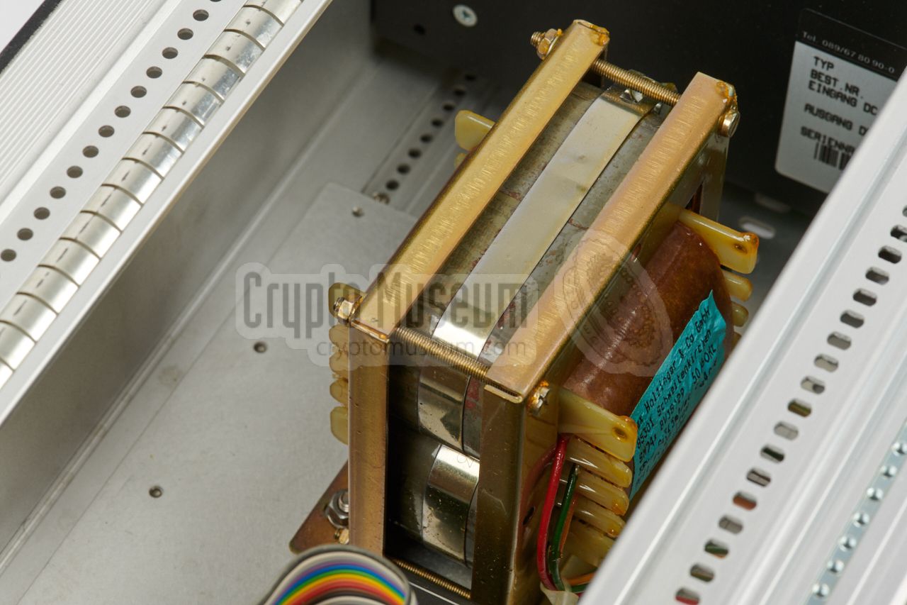
The power supply unit (PSU) is located at the far right of the case (when
viewed from the rear) and takes about
¼ of the total space. It consists
of a mains transformer and a series of
DC/DC converters, that convert
the 12V DC secundary voltage
into the voltages needed by the circuits.
Due to this approach, the unit can be powered from the mains as well as from
the 12V of a car battery.
Power is distributed to the plug-in cards via a wide backplane,
alongside the data lines. The generated voltages are 5V, 15V and 24V.
|
|
|
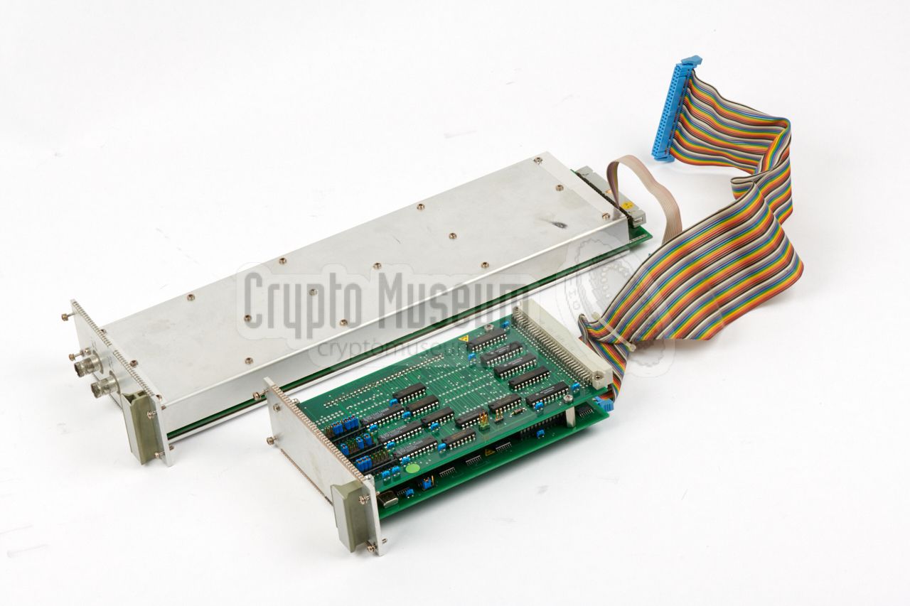
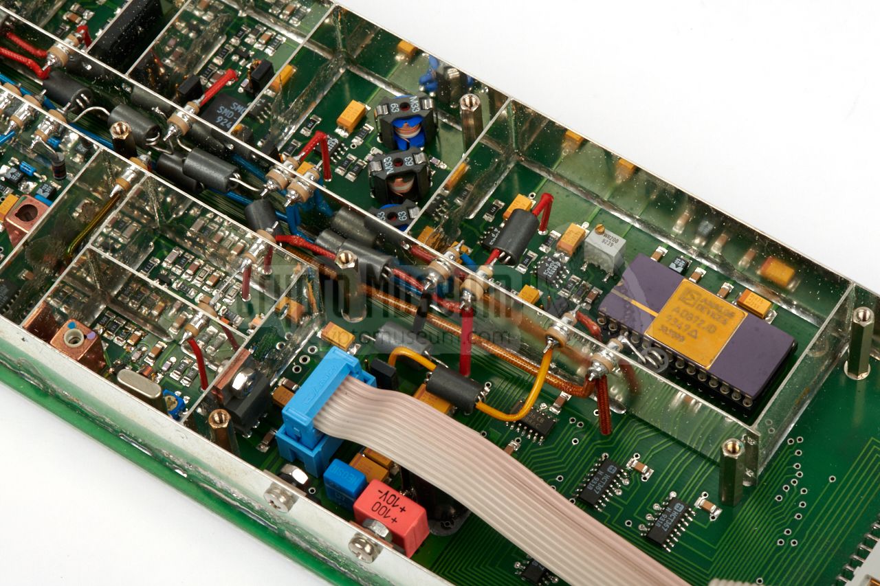
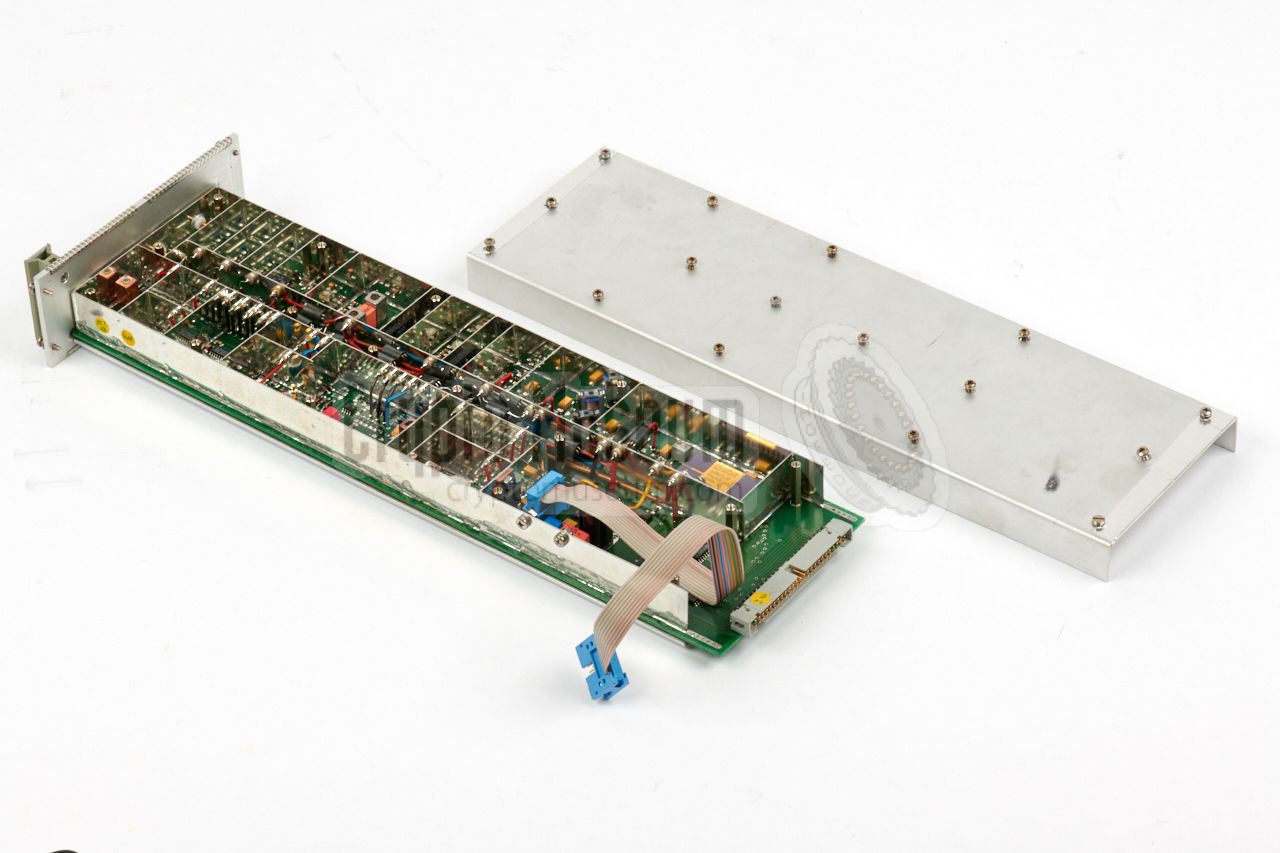
One of the most complex parts of the FFT Processor is the IF Unit,
which is also the only analogue part of the device. It is mounted
along the left side of the case (viewed from the rear) and is
completely shielded. It takes its input from the 10.7 MHz output
of the ICOM receiver.
At the far end of the card is an
Analog Devices AD872 A/D converter
that samples or digitizes the signal and passes it directly to
the FFT controller on the AMS bus.
➤ Datasheet
|
|
|
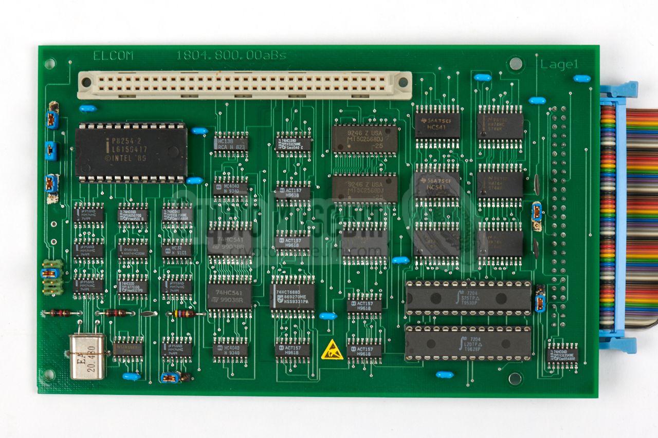
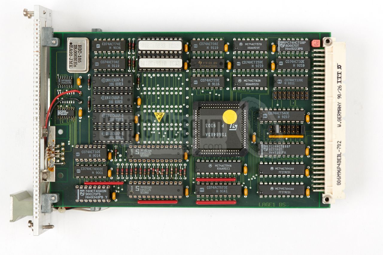
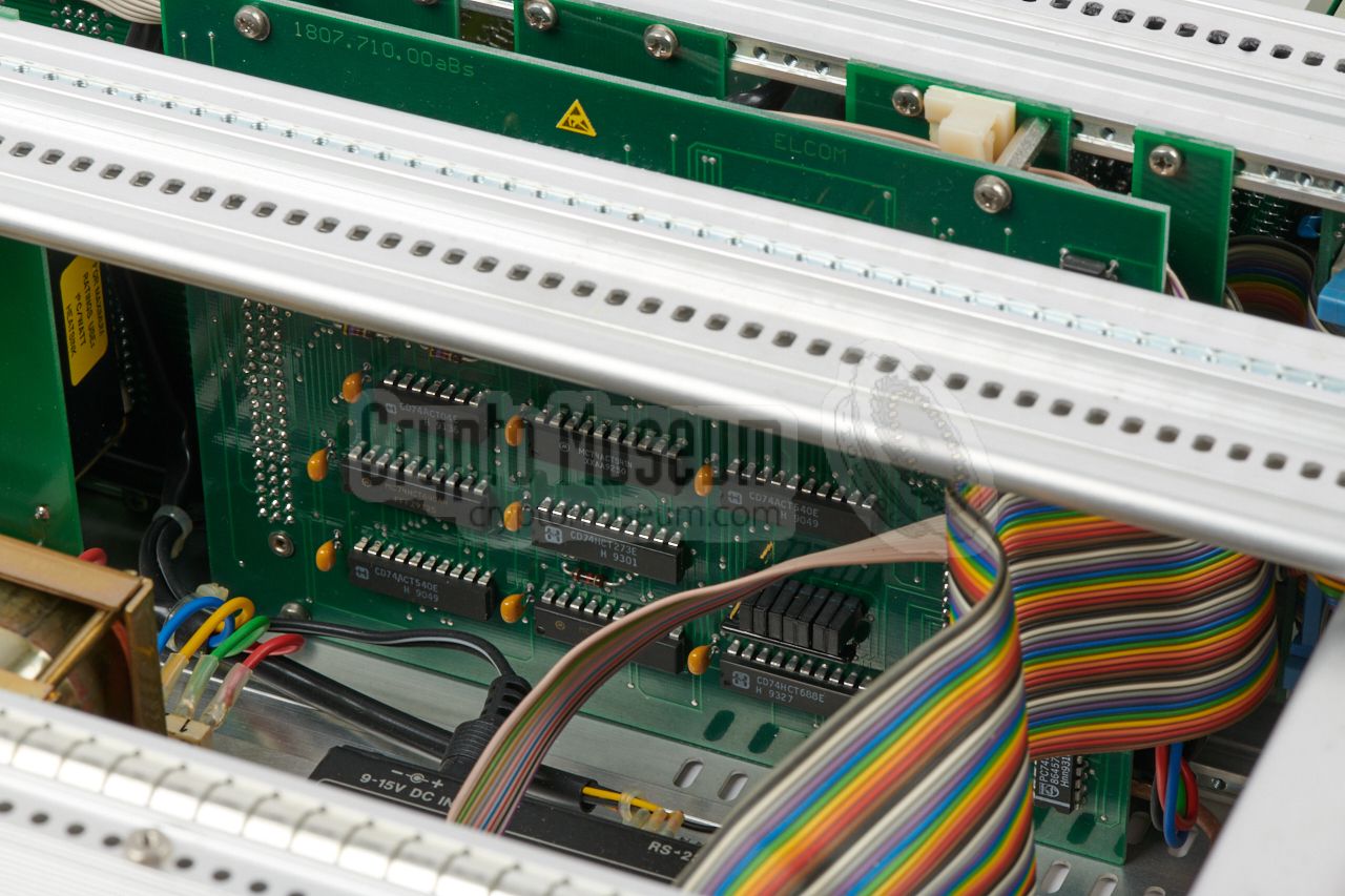
This card controls the functions of the IF interface and its
A/D converter. It ensures that the correct band segement are
sampled and sent to the FFT controller on the AMS bus.
The first card – visible in the image on the right – handles
the interfacing to the AT96/ISA96 bus. It also holds a series
of configuration jumpers. The card at the bottom controls the
IF Interface. The two
cards are inter-connected via an extra 96-way DIN connector,
located inbetween them.
|
|
|
|
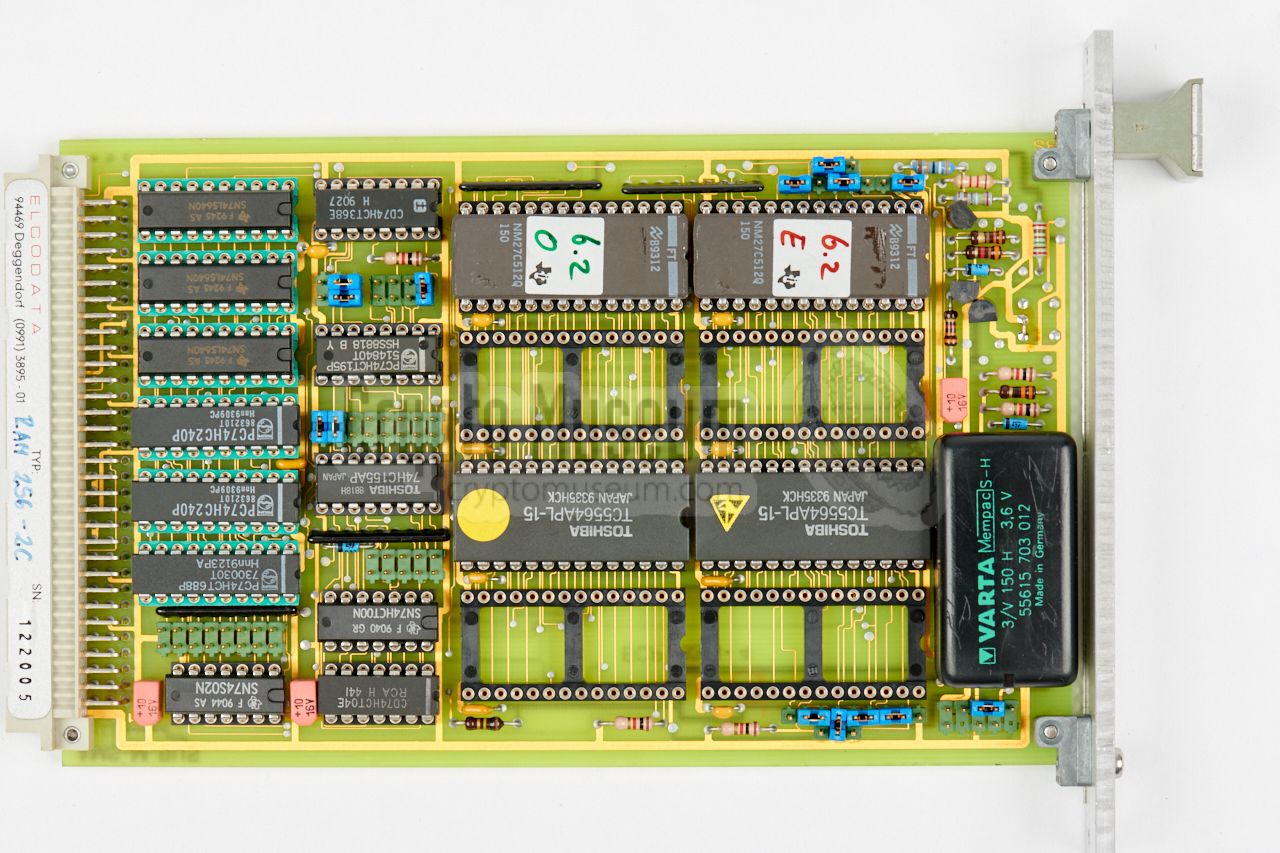
The image on the right shows the central processing unit, or CPU,
that controls the entire system. It bascially contains a standard
16-bit IBM PC with an Intel 386 processor on a single Eurocard-size PCB
(10 x 16 cm). At the time, it was a standard component for an
industrial AT96/ISA96 system, made by ELCODATA in Deggendorf (Germany).
|
|
|
To the right of the CPU card is a BNC socket, marked ICOM REMOTE.
It should be connected to the REMOTE socket of the
ICOM IC-R9000 receiver.
Behind the panel is not a plug-in card, but rather a
cable that leads to the ICOM CT-17 interface box
shown in the image on the right.
This interface is basically a level converter, that converts the serial
remote interface of the ICOM receiver into a standard RS232 data signal.
The output from the CT-17 interface is connected to the 2nd COM port of
the CPU card, and does not use hardware handshaking.
|
|
|
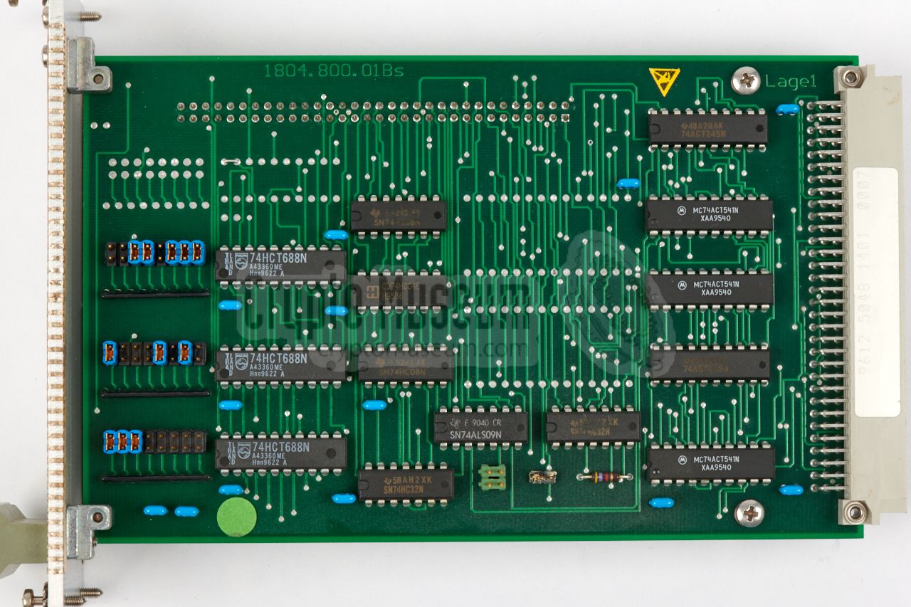
The input/output card (I/O) is responsible for communication with
the user. It holds an optical interface to the remote control unit
(RCU), which is handled by a separate SAB-80C537 microcontroller
made by Siemens. This leaves the main 386 CPU free to handle the
FFT conversion.
The I/O card also handles the selection of the appropriate antenna
input of the ICOM IC-R9000 receiver and the setting of the attenuator.
In the original technical documentation, this card was known as the
RF-Swich [A].
|
|
|
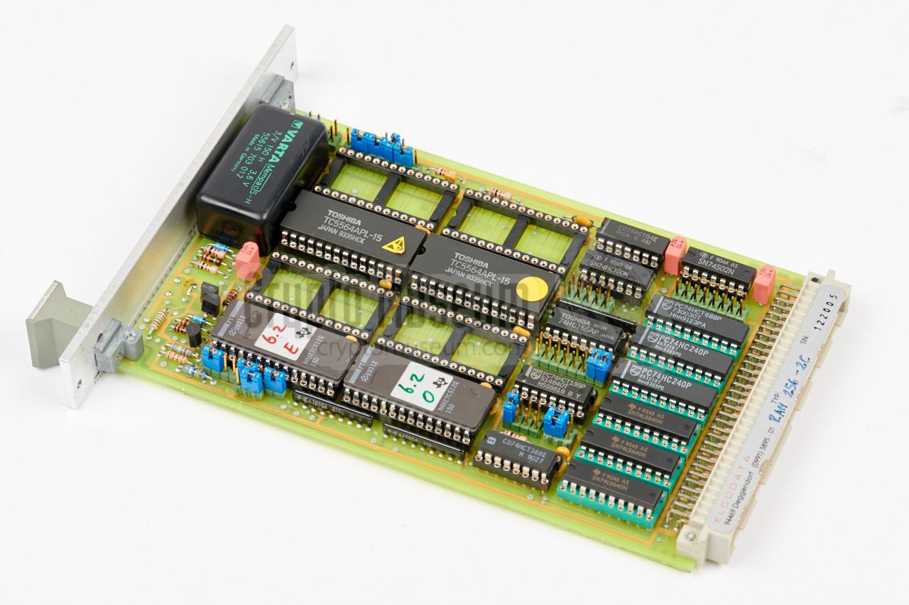
The image on the right shows the memory card which is connected
to the AMS-bus. It has 8 memory sockets of which
4 are populated. At the bottom left are the EPROMs which hold
the firmware of the system. As a 16-bit CPU is used, there are two
EPROMs (each covering 8-bits).
Above the EPROMs are two CMOS RAMs with a capacity of 8KB each.
At the top left is a 3V battery unit which retains the data stored
in the CMOS RAM chips.
|
|
|
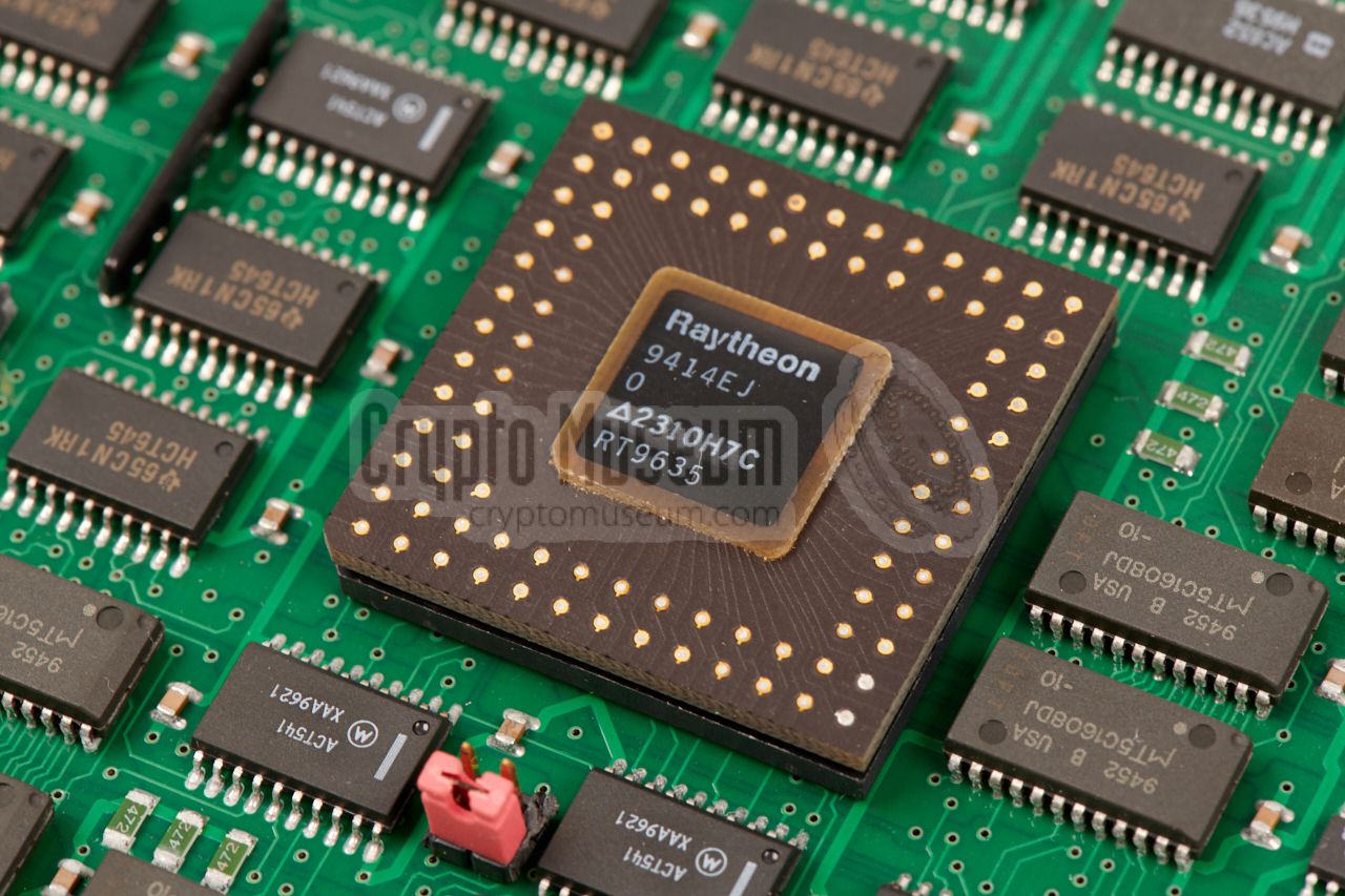
One of the most difficult tasks of the PAN-2000 is performed by the
FFT card, which is installed between the memory card (MEM) and the
display interface (VIDEO). It takes the samples directly from the
Inter Frequency (IF) card,
and converts it to the frequency domain so that it can be displayed
on the screen.
This conversion is done by means of a so-called Fast Fourier Transform
(FFT) algorithm, which requires a lot of processing power [5]. In the
PAN-2000 this is done with a special
TMC2310 FFT Controller, made by Raytheon
in the US [6].
|
|
|
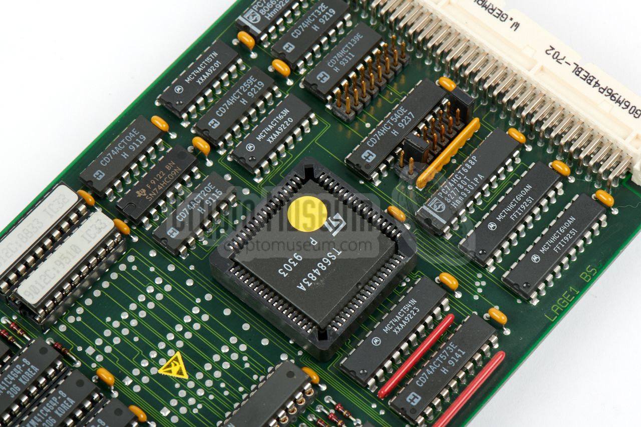
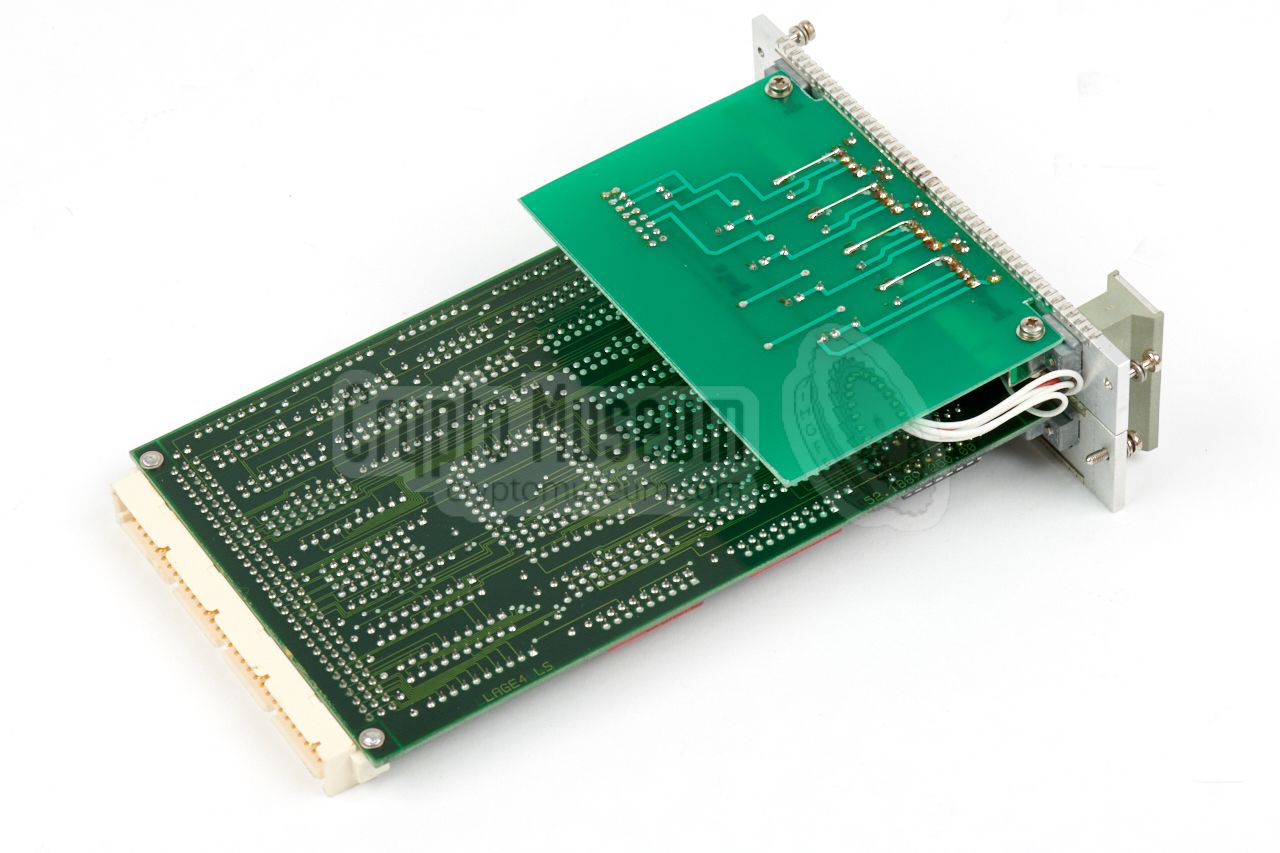
The graphics for the panoramic FFT display are delivered by the special
video card that is shown in the image on the right. It is fitted to
the right of the FFT card and consists of two PCBs: (1)
the actual video card
and (2) an optical interface.
It is built around a
TS68483A graphics controller.
Each of the video signals – luminance, horizontal sync (HS),
vertical sync (VS) and pixel clock (CLK) – are carried to the
display via a separate optical fiber. The optical fibre sockets
are recessed, to avoid damage when
the unit is installed in the trunk of a car. This can be
modified however.
|
|
|
In the PAN-2000 FFT Processor, two different BUS-systems are used:
the ISA96-bus (AT96-bus) and the AMS-bus. Although the cards for these
bus systems are very similar, they are not compatible. For this reason,
the FFT Processor has two different backplanes that are linked by a
so-called bus interface or bridge.
The image on the right shows the bridge card which is mounted behind
the two backplanes.
|
|
|
|
A major problem with the design of the PAN-2000 is the fact that —
like most IBM-compatible PC platforms — it has a BIOS 1 for which the
settings are stored in battery-backed CMOS RAM. For this, it is common
practice to use a NiCd battery, that is recharged when the device is powered.
|
As the PAN-2000 was made more than 20 years ago, the NiCd battery
is likely to be worn out by now, as a result of which the BIOS configuration
will have been lost, rendering the device useless.
In order to re-configure the BIOS, it is necessary to temporarily install
an AT/ISA96 VGA graphics card in the empty slot (marked 'X' in the
diagram above) and connect a VGA-compatible monitor (640 x 480). Also
required is a PS2-compatible keyboard, that should be connected directly
to one of the headers on the CPU card.
This card is not installed by default and is extremely rare.
|
|
|
|
Many thanks to Nico van Dongen (PA3ESA) for finding the only working VGA card
in the country and getting it on loan temporarily. With this card he was able
to reconfigure the BIOS of the PAN-2000 system featured here and bring it back
to life. He also replaced the NiCd backup battery.
|
|
As the PAN-2000 was developed in the mid-1990s — now well over 20 years
ago — some repair and restoration is inevitable. The device has seen
a significant mobile service life, and has been stored under uncontrolled
conditions for several years once it was decomissioned in 2005-2007.
|
The first thing to worry about is to make suitable cabling for the
system, as the original cabling has been lost. Once the wiring is in place,
the unit can be tested. Note that the PAN-2000 FFT Processor has to be
connected to a modified
ICOM IC-R9000 receiver. A standard IC-R9000
will also work, albeit with reduced performance.
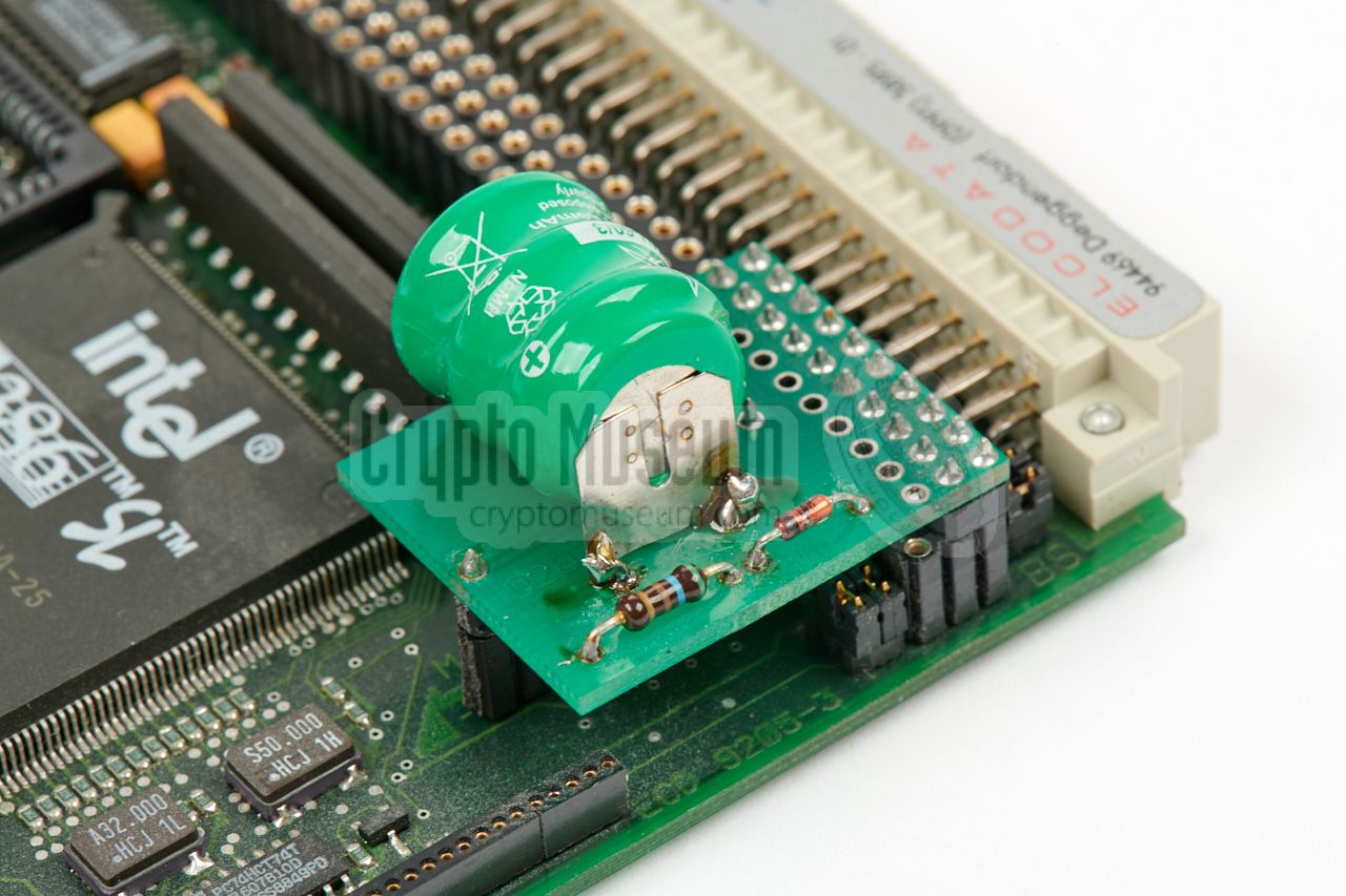
A serious problem is that of the backup battery on the processor card,
which retains the CMOS memory that holds the BIOS of the system. It is
very likely that after so many years this battery is flat and that the
BIOS settings have been lost.
|
|
|
|
This problem can be solved by replacing the rechargeable backup battery
as shown in the image above. Once the battery has been replaced the BIOS
settings must be restored manually, but this introduces a new problem:
it needs a PC keyboard and an ISA96-compatible VGA graphics card.
|
The first problem can be solved by making a suitable adapter cable and
connecting a standard PC/XT or PS2 keyboard to the CPU card. The second
problem is more difficult, as
compatible cards
are no longer available
and the previous owner (RCD/AT)
had only one such VGA card.
Luckily, with help from Nico van Dongen [1]
and Marcel Rohrs [2],
we were able to borrow the only remaining VGA card and configure BIOS
of the system. Another possible solution would be to convert an existing
ISA VGA card or a PC/104 VGA card for connection to our ISA96/AT96 bus.
|
|
|
|
With the previous problems solved, we were able to switch the PAN-2000 on
for the first time in years.
It worked straight away, but various types of glitches were observed on
the FFT spectrum display. Sometimes the image showed excessive noise —
originating from inside the device — sometimes a saw-tooth signal
appeared and sometimes the spectrum was gone completely.
|
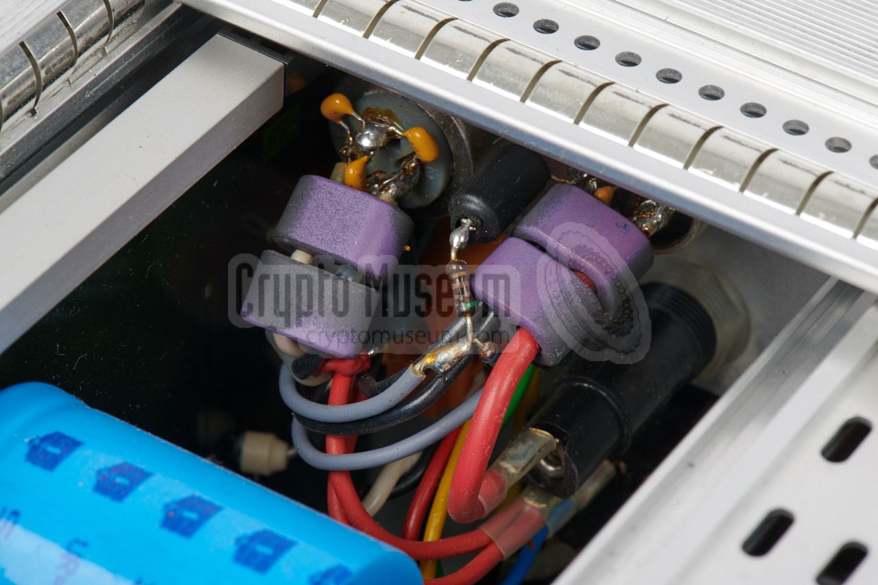
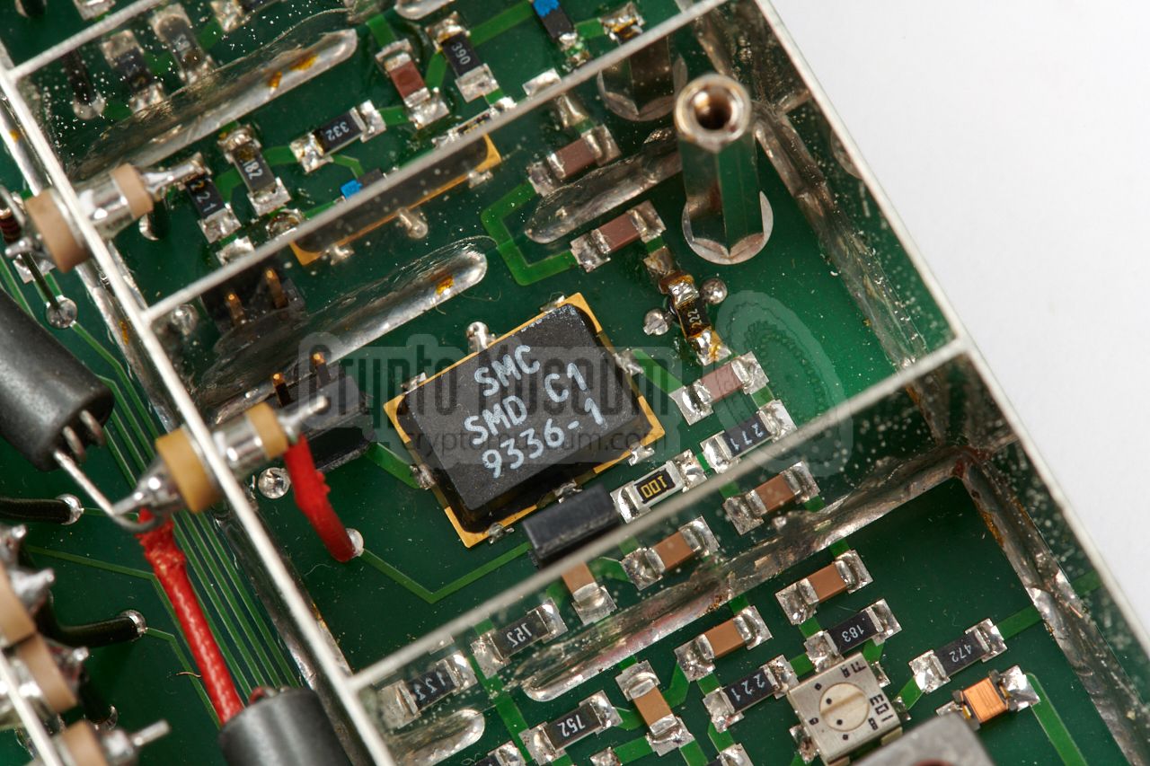
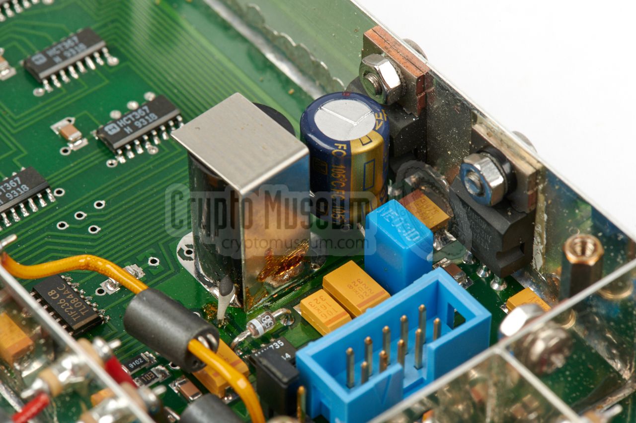
Tapping the enclosure had some effect on the glitches, and it was
concluded that the IF Interface was responsible for the problems.
The IF Interface is a beautifully built but very complex device, that can
be the root cause of several problems. First off all we replaced the
square red 100µF electrolytic capacitor
in the negative power circuit. Next we
resoldered all three power stabilizers that are located in the same area.
And finally, to reduce any spurious signals (birdies), we cleaned the outer
edges of the shielding on both sides with an ereaser.
|
|
|
|
As an extra safety measure, we
added a heatsink to the AD872 A/D converter,
which appeared to produce substantional heat. Adding a heatsink will increase
its lifespan. Once this was done, the IF Interface was closed again. When
doing this, ensure that all hex mounting stubs are properly fitted on both sides
of the PCB, that all screws are present, and that they are properly tightened.
|
The image on the right shows the extra heatsink that was glued onto the
A/D converter. Note that in the original design — the same IF interface was used
as part of the
Telefunken PSG-1800 panorama display
— a heatsink was also present in this place.
The image also shows the cleaned upper edges of the shielding that ensures a
proper contact with the aluminium-padded lid.
Once the repaired IF interface was re-installed, the PAN-2000 was switched ON
again, this time without any noticable glitches in the spectrum and without
any spurious signals, or birdies.
|
|
|
|
The only thing left now, was the
ICOM IC-R9000 receiver. As the original
– modified – receiver had been lost, we had to settle for a standard one.
Although the PAN-2000 can be operated with an unmodified R9000, the performance
will be sub-standard due to several quirks in its design.
|
Modifying an IC-R9000 for use with the PAN-2000 is not for the faint of heart.
It involves not only replacing a couple of connectors and part of the wiring,
it also requires serious modification of a number of densely populated boards
and a complete re-alignment of the entire receiver.
If you happen to have a PAN-2000 with an unmodified R9000 receiver, think twice
before you start modifying it. If you are uncertain, you may want to carry out
the simple modifications first, so that the receiver can at least be used
with the PAN-2000 for initial demonstration purposes.
|
|
|
|
During the 1970s and 80s, the Netherlands was flooded with clandestine
radio stations (pirates) operating in the MW/AM and VHF/FM broadcast bands.
In an attempt to counter the illegal use of the (limited) frequency space
and to reduce interference caused by such transmitters, the Dutch Radio
Monitoring Service – at the time known as the
Radio Controle Dienst (RCD) –
had its own purpose-built intercept receiver, which became known as the
PAN-1000 (panoramic 1000 MHz).
|
PAN-1000 was developed by the
Dutch Radar Laboratory (NRP)
and was introduced in the early 1980s, at the height of the clandestine
activity. In total, approx. 30 systems were
built at a unit cost of NLG 160,000 (EUR 73,000). They were delivered to
the RCD over the next few years in several batches. Most systems were
built inside the trunk of a regular car, with the controls and display
within reach of the driver/investigator.
By the early 1990s, the PAN-1000 had to be replaced and the need had arisen
for a wider frequency range, preferably up to 2000 MHz.
|
|
|
|
Due to the high price of the PAN-1000 and the meanwhile significantly reduced
budget of the RCD — by that time known as
HDTP-RDR — the order
was not given to the NRP,
but to ELCOM in München (Germany).
The new receiver would become known as the PAN-2000. Approximately 20
units were ordered, at a unit price which was reportedly
a fraction of the old PAN-1000 price.
|
|
The IF interface was adapted for the 10.7 MHz IF signal from the
ICM IC-R9000 receiver and the internal 10 MHz reference oscillator
was used, rather than an external one. Furthermore, the IF
controller and the firmware were adapted in such a way
that a maximum span of 10 MHz could be shown on the panarama display,
processed as 5 individual segments of 2 MHz each.
|
-
Over the years, Telefunken products were also sold under the
AEG, DASA, EADS, TST and Racoms brands.
|
The PAN-2000 was developed as the successor to the
PAN-1000, which had been
developed in the early 1980s by the
Dutch Radar Laboratory (NRP), especially
for the Dutch Radio Monitoring Service (RCD).
As the name suggests, it is suitable for frequencies up to 1000 MHz (1 GHz).
It offered a superior performance over the entire 100 kHz - 1 GHz
frequency range, with virtually no spurious signals, but had a price tag
of no less than NLG 160,000 in 1983 (~ EUR 75,000).
➤ More information
|
|
|
|
Below is the pinout of the various sockets and connectors of the
PAN-2000 core components.
The pinout of the sockets of the
ICOM IC-R9000 receiver
and the TAIYO TD-L1706 direction finder
can be found on their respective pages.
The layout of the rear panel of the ELCOM FFT
Processor is shown above.
The following sockets are available on the FFT processor:
|
PSU-ST1 Mains input (220V AC) PSU-ST2 12V DC input (and switch signal) PSU-BU1 12V DC output for DF unit and 15V output for receiver) VIDEO-BU1 Analogue video (not present) VIDEO-VS Display vertical sync (optical link) VIDEO-HS Display horizontal sync (optical link) VIDEO-CLK Display pixel clock (optical link) VIDEO-VID Display video (optical link) I/O-ANT IN Antenna input (usually from manual antenna selector) I/O-ANT 1 Antenna 1 input of ICOM IC-R9000 (50 ohm coax) I/O-ANT 2 Antenna 2 input of ICOM IC-R9000 (50 ohm coax) I/O-ANT 3 Antenna 3 input of ICOM IC-R9000 (50 ohm coax) I/O-CONSOLE RCU TxD (optical link) I/O-TUNING ICOM IC-R9000 CM-OUT (coax) RM-ICOM REMOTE ICOM IC-R9000 REMOTE (coax) CPU-ST1 RS232 serial port (for connection of PC) IF-BU1 IF input (from ICOM IC-R9000) (coax) IF-BU2 IF output (to TAIYGO TD-L1706) (coax)
|
- Battery (+)
- Battery (-)
- Switch input (+12V from console)
|
|
- +15V DC (for receiver)
- GND
- +12V DC (for direction finder)
|
|
|
This is a full serial RS-232 port for connection of a personal computer (PC).
It is the first serial port (COM-1) of the CPU card, and is configured at
9600 baud, 8-bits, no parity, 1 stopbit (8N1). Full hardware handshaking is
supported. This port basically duplicates the
functionality of the console.
The accepted command protocol is specified in the technical manual [A p.28].
|
- GND
- TXD
- RXD
- RTS
- CTS
- DSR
- GND
- DTR
|
|
|
The remote control unit (RCU) has several connections for power and other
peripherals. Below are the pinouts of all sockets that are located at the
rear side of the RCU, starting with the DB-9 socket that carries the 12V
DC power lines (looking into the socket):
|
- Audio line in (from IC-R9000 LINE OUT)
- (-) 12V DC (GND)
- Relay out for Taiyo DF unit (via DIR FINDER switch)
- (-) 12V DC (GND)
- (+) 12V DC input
- (+) 12V DC output (switched via POWER ON switch)
- n.c.
- n.c.
- n.c.
|
|
|
At the rear of the remote control unit is a 5-pin 180° DIN socket
for connection of a (tape) recorder. It follows the regular pinout
of mono audio equipment, when looking into the socket:
|
- LINE OUT
- GND
- n.c.
- n.c.
- n.c.
|
|
|
The RCU also has a socket for connection of a loudspeaker, of which the
volume can be adjusted with the volume control on the RCU. The pinout
is identical to the speaker socket of the earlier PAN-1000, so that its
speaker can be used straight away:
|
- Speaker 4Ω
- n.c.
- Speaker GND
- Direction finder on/off
- Direction finder on/off
|
|
|
Also on the RCU is an SMA/F socket marked RATELAAR (English: Rattle).
This socket should be connected to the 1/100 output of the DARE CR-300/C
frequency counter and allows the frequency in the counter's display to
be copied to the PAN-2000, when pressing the COUNT-button on the RCU.
|
|
Under normal circumstances it should not be necessary to connect a keyboard
to the PAN-2000, but in case the BIOS settings are lost, this might be
required.
In that case, install an AT96/ISA96 graphics card in the slot (X) to the left
of the CPU and connect an IBM keyboard to the CPU board.
|
- Vcc +5V
- KDAT
- KCLK
- do not use (turbo L)
- MCLK
- MDATA
- do not use (turbo M)
- n.c.
- n.c.
- GND
|
|
- KCLK
- KDAT
- not connected
- GND
- Vcc (+5V)
|
|
- KDAT
- MDAT
- GND
- Vcc (+5V)
- KCLK
- MCLK
|
|
Device Monitoring and surveillance receiver Purpose Locating clandestine radio transmitters and sources of interference Model PAN-2000 Manufacturer Elcom GmbH Years 1995-2007 User RDR, (AT) Frequency ? — 2 GHz Quantity 20 ~
|
Input 10.7 MHz (IF from receiver) Impedance 50Ω Level -40 dBm (for maximum display) Frequency span 100 kHz, 250 kHz, 500 kHz, 1 MHz, 2.5 MHz, 5 MHz or 10 MHz Non-linearity ± 0.2% Windowing Hamming Resolution 256 bit Display rate 10/2 — 30/s (depending on span) Input range -110dBm — +10dBm Attenuator IF: 50dB (in 10dB steps), RF: 60dB (in 10dB steps) Acuracy ±3dB Image rej. > 70dB Intermod. < 70dBm Dynamic range 70dB Display range 80dB Display MODE Normal, Average, Maximum, Freeze Memories 100 1 Power AC 120/240V AC (selector), 48 — 66 Hz, 200mA @ 220V AC Power DC 9.5V — 18V DC, ~ 4.4A @ 12V DC Power out 15V DC ±5%, 7A Temperature 0°C/+50°C, operational: -20°C/+55°C, storage: -40°C/+70°C Dimensions 464 x 443 x 132.5 mm
|
Display type Electroluminescent (EL), raster scanning display Resolution 512 x 256 (2:1) Active area 233 x 136 mm Refresh rate 50 Hz Intensity Adjustable with knob DC input 11 — 30V DC, ~ 500mA @ 12V DC Data input 4 x optical fibre (plastic) Dimensions 268 x 146 x 40 mm
|
Counter 2 0dBm, 50Ω Resolution 2 10 Hz (10kHz—300kHz), 100 Hz (300MHz–20MHz) Speaker 4Ω Recording 600Ω Power 9 — 14V DC Current ~ 200mA @ 12V DC Data 1 x optical fibre (plastic) Dimensions 222 x 115 x 92 mm
|
-
The following parameters are stored with each memory position: frequency,
span, IF mode, IF bandwidth, attenuation, display mode and scan mode.
-
This refers to the input marked RATELAAR at the rear of the Console. This
input should be connected to the 1/100 output of the
CR-3000/C frequency counter.
|
|
AMS
|
|
Advanced Microcomputer Systems
16-bit computer bus-architecture with real-time facilities and multi-processor
capability, initially developed in 1974 by Intel as Multibus [8].
Later adopted as the IEEE 796 bus. In Europe also knows as the IEC 796
standard and as AMS-bus.
➤ Wikipedia
|
|
BIOS
|
|
Basic Input/Output System
On an IBM-compatible PC platform, the BIOS is a piece of non-volatile
firmware that is used to perform hardware initalisation during the start-up
process of the platform (booting). In most cases, the configuration of the
BIOS is held in a volatile battery-backed CMOS RAM.
➤ Wikipedia
|
|
DF
|
|
Direction Finding  RDF RDF
|
|
FFT
|
|
Fast Fourier Transform
Mathematical algorithm that samples a signal over a period of time
(or space) and divides it into a (finite) number of frequency components.
In this context, the FFT converts the sampled IF signal from the ICOM
receiver from the time domain to the frequency domain, so that it can be
displayed as frequency spectrum activity.
➤ Wikipedia
|
|
ISA
|
|
Industry Standard Architecture
➤ Wikipedia
|
|
RCU
|
|
Remote Control Unit
In this context, RCU refers to the central control unit of the PAN-2000.
Also known as the CONSOLE.
|
|
RDF
|
|
Radio Direction Finding
Generic name for the processing of finding the direction of a (radio)
transmitter. Also known as Direction Finding (DF).
|
- PAN-2000 Technical Manual - Part 1 Description (German)
ELCOM GmbH, mid-1994. 65 pages.
- PAN-2000 Technical Manual - Part 2 Circuit diagrams
ELCOM GmbH, mid-1994.
- FFT Controller TMC2310, Datasheet
Raytheon, TRW. Revision D, November 1990.
- A/D Converter AD872A, Datasheet
Analog Devices, Revision A, November 1997.
➤ Obsolete — Replaced by AD871
- TS68483A Advanced Graphics Controller, datasheet
SGS-Thomson Microelectronics, September 1993.
|
- Nico van Dongen (PA3ESA), PAN-2000 and system description
Crypto Museum, July 2018.
- Marcel Rohrs, Previous owner of several PAN-2000 systems
Crypto Museum, July 2018.
- AT/RCD technician, Personal correspondence
April 2018 — August 2018.
- Wikipedia, Industry Standard Architecture
Retrieved July 2018.
- Wikipedia, Fast Fourier transform
Retrieved July 2018.
- Raytheon, TMC2310 FFT Controller, datasheet
Revision D, November 1990. Retrieved July 2018.
- Wikipedia, TOSLINK
Retrieved July 2018.
- Wikipedia, Multibus
Retrieved July 2018.
- Wikipedia, Moiré pattern
Retrieved July 2018.
|
|
|
|
Any links shown in red are currently unavailable.
If you like the information on this website, why not make a donation?
© Crypto Museum. Created: Wednesday 11 July 2018. Last changed: Monday, 25 May 2026 - 07:42 CET.
|
|

|
|
|


![Optional VGA card for AT96/ISA96 bus. Photograph kindly supplied by Nico van Dongen [1].](img/VGA_large.jpg)