|
|
|
|
|

|
|
RX DF NRP RCD PAN-2000 →
Panoramic monitoring receiver
PAN-1000 is a high-end monitoring receiver in a 19"
rackmount case, designed and built in the early 1980s by the
Dutch Radar Laboratory (NRP),
for use by the Dutch Radio Monitoring Service, at the time known as the
Radio Controle Dienst (RCD)
and part of the Dutch Post Office (PTT).
It was used for finding clandestine radio stations (pirates)
and is also known as the NRP receiver.
The name PAN-1000 was derived from PANORAMIC and the maximum
frequency (1000 MHz).
|
In the Netherlands, RCD was mandated by law
for locating and taking down
clandestine radio stations. As high-end monitoring and intercept
receivers were not commonly available at the time, the RCD decided to
commission the NRP with the development of a purpose-built one.
Development took several years and the ordered units were delivered
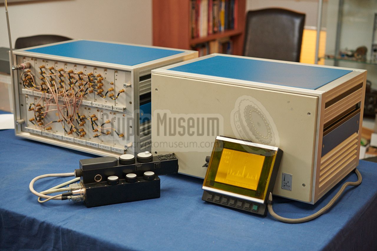
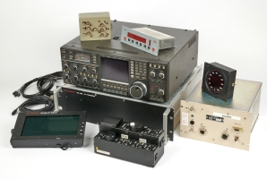
over a period of five years. The image on the right shows a complete PAN-1000
system, consisting of a large 19" rack with the
various RF, IF and AF modules, a small PSU,
a display, an interface
and a remote control unit.
|
|
|
The radio is extremely well built, is sensitive and has a
consistent behaviour — accurate within 1dB — over its entire frequency
range to 1 GHz, despite the fact that it consists of 6 individual receivers.
From 1983 to 1987, between 30 and 40 PAN-1000 units were delivered by
the NRP
[1], for a price of NLG 160,000 each (approx. EUR 73,000).
The exact number of receivers is unknown at this time, as spare units
and additional units were built for other Government agencies as well.
Some PAN-1000 systems were later extended with a
TAIYO direction finding unit
of which the flat antenna was concealed as the sunroof
of the car. During the 1990s, when new intercept receivers were needed,
the PAN-1000 was considered too expensive. As a replacement, a standard
ICOM IC-R9000 receiver
was expanded by the German company ELCOM
with an external FFT processor, a panoramic display and a new remote
control unit that was similar to the PAN-1000 one.
The new receiver was designated PAN-2000 and
was often combined with a
TAIYO direction finder.
➤ History of the PAN-1000
|
The Power Supply Unit (PSU) and the Main Unit (RX) were usually mounted
in the trunk, with two cables – carrying power, data and audio –
running to the front of the car.
The graphical display (DSP) was connected to the main unit via a display
interface unit (INT), and the custom-designed Remote Control Unit (RCU)
was connected to both the display interface (INT) and the Main Unit.
The block diagram above shows how the various components are interconnected.
All controls are located on the RCU, except for the preset buttons and
the brightness control, which are part of the display.
When in use, the complete PAN-1000 set consumes
slightly less than 6A (at 12.6V).
The complete PAN-1000 system was designed in such a way that it could be
conveniently built inside the Ford Grananda and Peugeot 204 cars that were used
by the agency at the time. The drawings below show the position of the
various components inside the Ford Granada in 1984.
The 19" racks (1) and
(2) are mounted in the trunk,
commonly in a heavy outer frame with shock mountings, as shown in the
original brochure [D].
The interface between the receiver and the display would be fitted inside
the glove compartment (3) of the car,
whilst the display itself was mounted on the dasboard (4). Finally, the
remote control unit was mounted between the seats,
just aside the handbrake (5).
The antenna was mounted somewhere on the body of the car (6).
|
|
The PAN-1000 covers all frequencies between 100 kHz and 1 GHz and was
suitable for virtually any intercept job at the time, although it
did not have Direction Finding (DF) capabilities. Instead, the operator would
measure field strength, in combination with a set of attenuators and
a high-resolution field strength meter (with a linear or logarithmic scale)
on the system's plasma display.
|
The attenuator
could be operated directly from the RCU. Additionally,
the field strength meter could be switch from a logarithmic scale to
a linear one, giving a much better dynamic range in close proximity of the
clandestine transmitter.
The entire system was designed in such a way that it could be
controlled by a single person who was driving the car at the same
time. For this reason, cars with an automatic transmission were
generally used. The frontmost dial is used for tuning to the
desired frequency in small steps. Push-buttons are used for
larger steps.
|
|
|
Once the receiver was tuned to the desired radio station,
the investigator started driving around in order to find a direction
in which the signal strength would increase. If the signal became too
strong, he would use the second dial to select an appropriate
attenuator (between 0 and 120 dB).
Finally, when the receiver was in close proximity of the transmitter,
the attenuator would be set to its maximum (120 dB) and the S-meter
would be switched to linear scale. Whilst driving past the location
of the transmitter, the meter would clearly indicate a peak value.
The investigator would usually repeat the last step several times,
to be sure that the right house was entered.
The entry frequency span from 100 kHz to 1 GHz is divided over six
main bands that are handled by six individual converters, each with
their own sub-bands. There is a small overlap between the bands, that
can be useful when investigating signals right at the border between
two bands. The receiver has a built-in frequency hysteresis,
that avoids switching to the other converter at that point, depending
on whether you are tuning up or down, as illustrated in the diagram
above.
The internal IF converters and synthesizer frequencies are choosen
in such a way that spurious signals (birdies) are avoided as much as
possible. In this respect, the PAN-1000 still outperforms many modern
receivers today.
Another unique feature of the PAN-1000 is the large 100 MHz frequency span
of the display in the 500 - 1000 MHz band that greatly helped the
discovery of clandestine TV stations in this part of the spectrum;
a typical problem of the 1980s.
|
|
The simplified block diagram below shows how the various modules
are connected together. The frequency range from 100 kHz to 1 GHz
is divided over six main bands. The input selector feeds the
antenna signal, via an adjustable attenuator, to the selected converter.
Inside each of the six converters, the band is further divided into sub-bands that
are each processed independently.
|
➤ Download block diagram as PDF
At the bottom right is a complex set of digital frequency synthesizers
that together determine the frequency of the bands and sub-bands of each band
module, in such a way that hardly any internal spurious signal (burdies)
are generated. The receiver produces two independent outputs, one of which is
used to give a panoramic view of the selected frequency, whilst the other one
is further processed and demodulated into an audible signal. Frequency setting
is under control of three microprocessors (µP),
one of which is located in the receiver cabinet (RX) as
module #14.
|
TIP — Click any of the modules in the above block diagram for a detailed
description and hi-res images.
The PAN-1000 consists of 6 converters that each cover a part of the supported
frequency range. These converters can be seen as six individual receivers.
With exception of the lowest frequency range (0.1 - 31.25 MHz),
each converter has two internal frequency mixers.
It delivers an output signal of 50 MHz which is mixed in a 3rd IF stage
down to 10.7 MHz before it is fed to the FM, AM and SSB demodulators.
This concept can best be described as a triple-super-heterodyne.
The only exception to this rule is the converter for the lowest frequency
band (module 7, 100 kHz - 31.25 MHz), which has only one IF stage and is
therefore a double-super-heterodyne receiver.
The signals for the 1st and 2nd mixers are generated by a complex set of
digital frequency synthesizers (modules 15 - 19), all of which are under
control of the internal microprocessor (module 14, µPS).
The first signal – here denoted as Synthesizer 1 – is a variable frequency
that is responsible for tuning.
The second synthesizer produces a fixed frequency of 240 or 360 MHz.
|
|
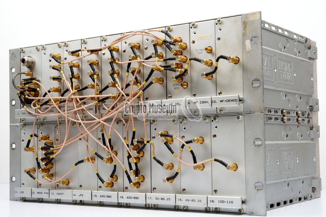
The main unit of the PAN-1000 system is the actual receiver itself.
It has a modular design and consists of a double Eurocard 19" rack
that holds the various modules.
Each half of the rack has its own backplane through which the power
lines, data lines and clock signals are distributed.
|
The image on the right shows the receiver rack. At the top row are 10
modules (marked 1-10). The antenna is connected to the Type N socket
of the first module (1) that contains a switchable attenuator followed
by a band selector relay.
The output of the band selector is fed to any of
the six RF converters (modules 2-7), each of which delivers its output
to the 50 MHz 3rd IF stage (module 8). The output of the 50 MHz stage is
passed to the 4th IF stage at 10.7 MHz (9) and finally to the demodulator
(10), which converts it into an audible signal for the RCU.
|
|
|
The bottom row holds 9 modules (marked 11-19), some of which are wider
that the others. The first three modules are part of the panorama viewer,
which consists of a sweep generator (13), a mixer (12) and a logarithmic
amplifier (11). The mixer gets its input from each of the six band converters
in the top row (2-7). The output of the logarithmic amplifier (11) is
fed to the input of the µPS microprocessor unit (14),
where it is sampled by an A/D converter. The microprocessor passes it
on to the display interface unit (INT) that presents it on the
panoramic display (DSP).
All connections between the various modules are made
by means of high-quality teflon coax cables with SMA connectors
at either end. The rack allows each module to be removed in
order to be serviced individually.
The receiver has no controls and was usually mounted in the trunk
of the car. Two multi-wire cables are used to connect it to
the RCU
and the display interface (INT).
➤ Detailed description of each module
|
|
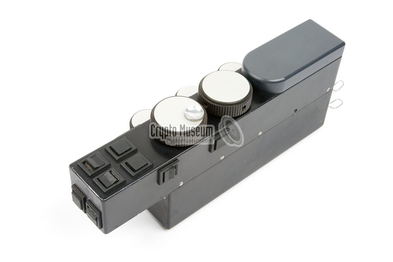
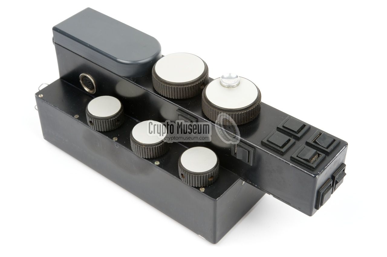
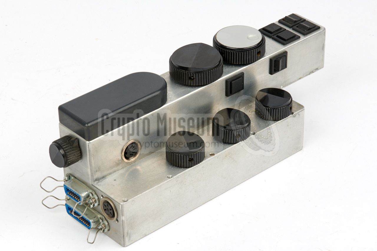
The custom-designed Remote Control Unit (RCU) measures approx. 26 x 7.5 x 11 cm
and was layed out in such a way that all controls were conveniently
located and could be identified by touch.
It was mounted in between the two front seats of the car
by means of velcro strips.
|
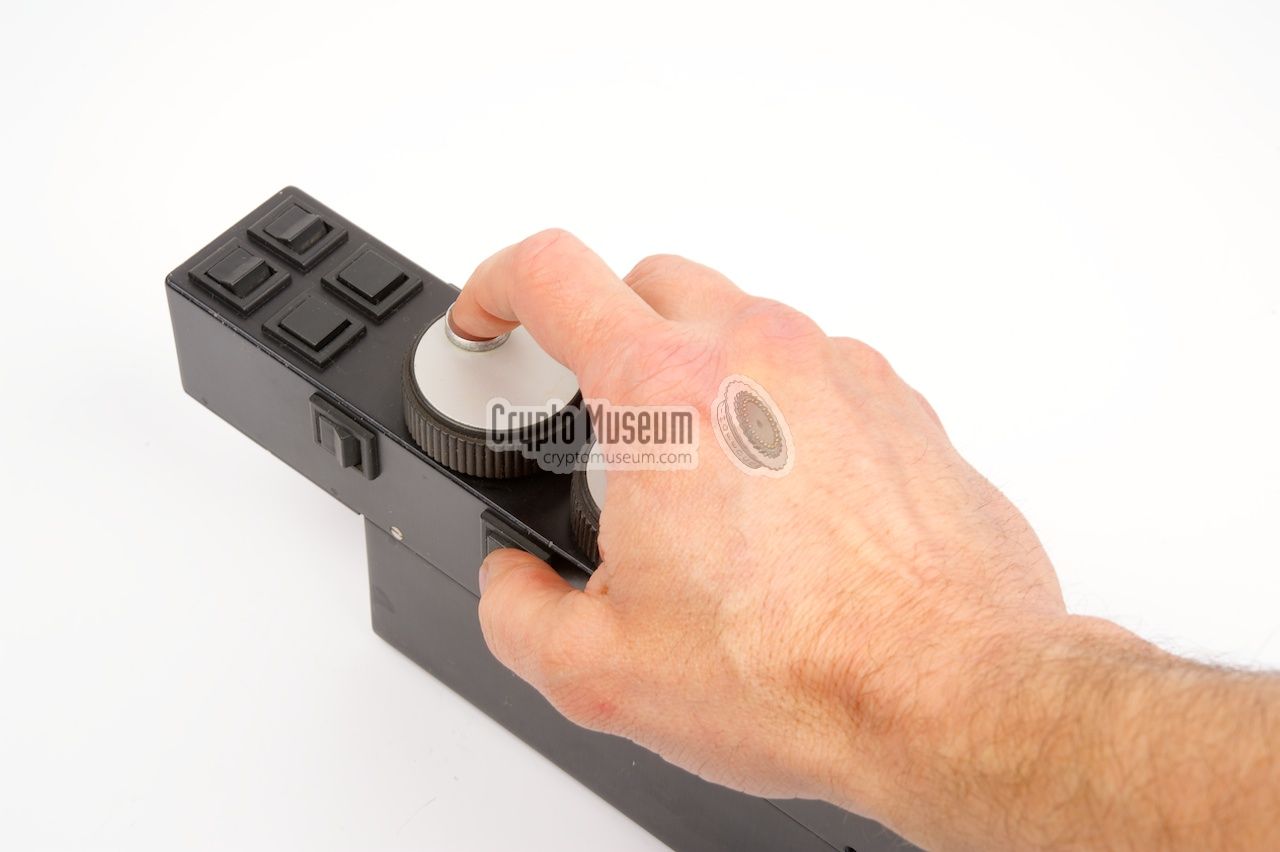
The image on the right shows the RCU a seen from the right. The driver could
place his right hand on the knobs
whilst driving the car, resting the palm of the hand on the rounded grey pad.
The two most important controls are located prominently at the top of the unit.
The frontmost dial is the tuning knob and one behind it is the
attenuator. The three knobs at the lower right are (front to rear)
clarifier, volume and squelch. The MODE
selector (AM, FM, SSB) is
located at the back of the unit, as it is hardly used.
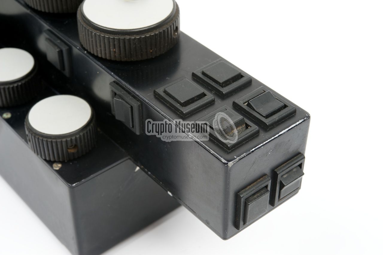
Various toggle switches and push-buttons are located at all sides of the
CU, within reach of the fingers.
|
|
|
|
There is no text or index on it, as the driver has no time
to look at the controls whilst driving. Furthermore, the device was often
operated in the dark. In practice, an operator quickly got used
to the controls as they are organized in an intuitive manner.
All connections to the main unit (RX),
the display interface (INT) and the
speaker are
at the rear, where also the MODE selector is found.
An isolated recording output (0dB into 600Ω)
is available on a 5-pin DIN socket at the right side.
|
|
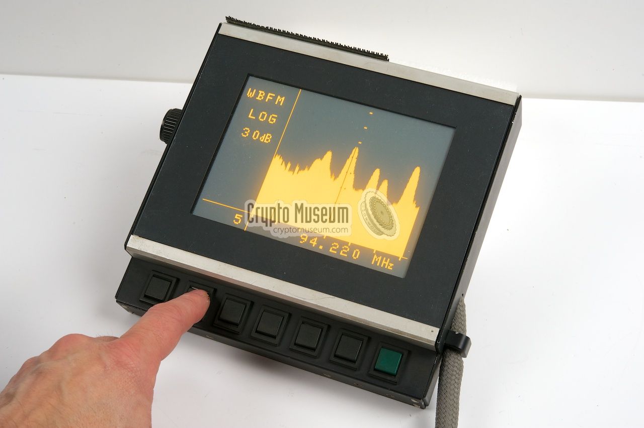
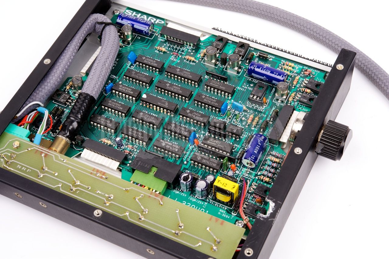
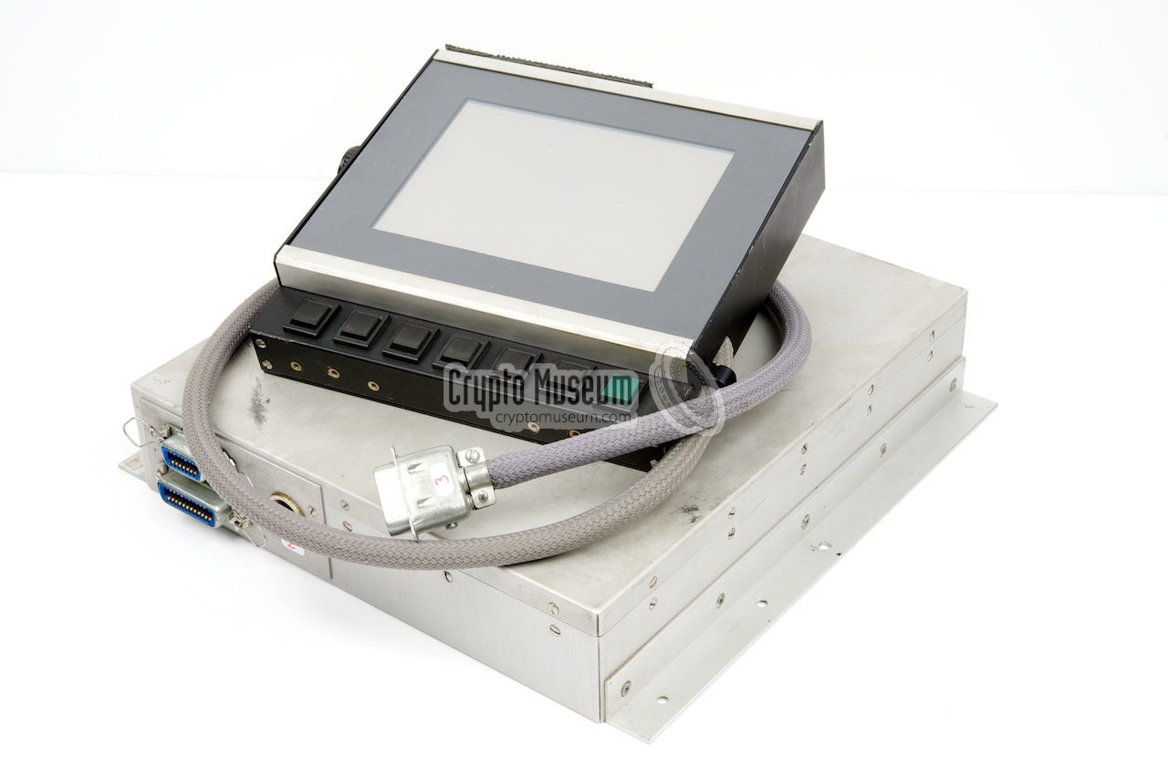
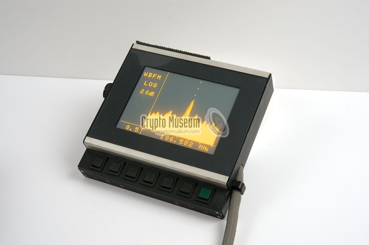
The display unit is used for the interaction with the operator.
It shows the current frequency, the current settings and the
panorama display. At the heart of the display unit is a
SHARP LJ-320U01 Electro-Luminescent (EL) Display,
also known as PLASMA, with a resolution of 320 x 240 pixels.
|
The display measures approx. 19 x 15 cm and was mounted on the
dashboard of the car, to the right of the steering wheel, in such
a position that the driver had a clear view whilst driving.
The display holds the necessary electronics
for driving and refreshing it. This driver board was supplied
by SHARP. It was connected to a
large external character and graphics generator
– also supplied by SHARP – that was part of the
display interface unit (INT).
For that reason, the interface unit had to
be placed as close to the display as possible, usually in the glove
compartment.
|
|
|
|
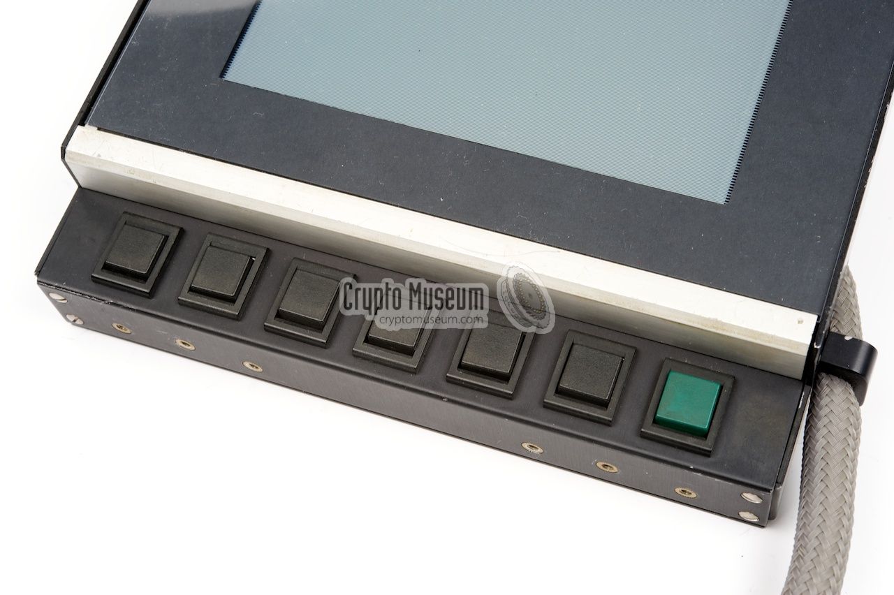
Below the display are 7 push-buttons.
The first six of these buttons are for recalling the presets.
The rightmost button is green and is used for storing a new preset.
After pressing the green button, the letter 'M' appears in the
display (Memory).
After subsequently
pressing one of the preset buttons,
the current frequency is stored in memory and the letter 'M' disappears again.
|
|
At the time the PAN-1000 was developed, microprocessors were not very
powerful yet, and graphics controllers were hardly available. Furthermore
it was difficult to find good displays, with sufficient resolution and
refresh rate, that could display text and graphics simultaneously.
|
The SHARP EL display that was selected for the PAN-1000 was by far the
best possible solution, but required a lot of extra electronics. Part of
these electronics – the display driver – were placed behind the display,
but the character and graphics generator was much larger and had to
be placed elsewhere, but not too far away.
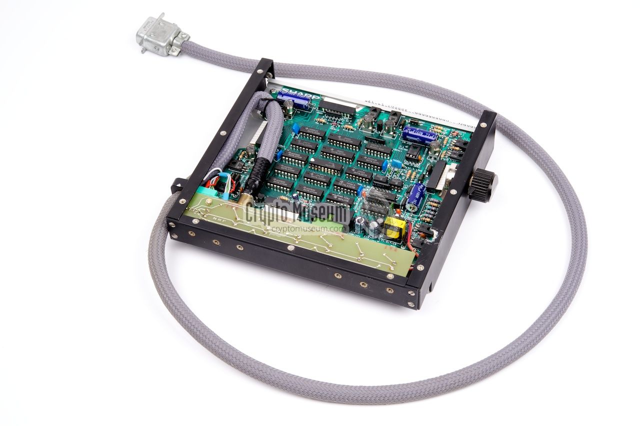
It was decided to place this board in a separate enclosure – shown in
the image on the right – that was
mounted inside the glove compartment of the dashboard.
It has two compartments, one of which
houses the display controller board.
|
|
|
|
The display controller board (DSP-A) is connected to the
display driver board (DSP-B, mounted
behind the display) via a short cable in order to avoid interference.
The display controller board is driven by one of the microprocessors (µP)
that are placed at the reverse side of the enclosure.
|
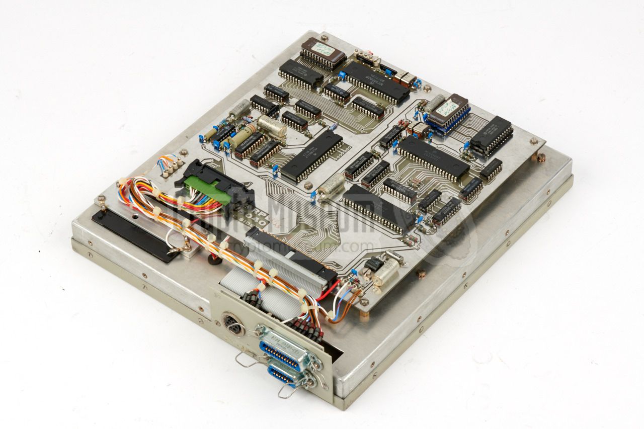
The other compartment of the interface unit holds two microprocessors:
µPC
and µPD.
The first one (µPC) is the control processor.
It reads the
state of the controls on the RCU and the push-buttons below the display,
and sends it to the system microprocessor at the main unit (µPS) via a
full-duplex asynchronous serial interface.
In return, the system processor (µPS) keeps the control processor (µPC)
constantly updated with panoramic data, which is passed via a parallel
interface (PIA) on to the
display processor (µPD)
which converts it into graphical display data.
|
|
|
|
The Power Supply Unit (PSU) was placed externally.
According to its front panel, it is designated MODULE 20.
It contains a relay – controlled by a switch on the RCU –
that supplies the raw 12V to the receiver. It also delivers
+15V and -12V for the EL display and the A/D converter respectively.
|
Although it seems overkill, the PSU is mounted on its own in the full-width
19" Eurocard rack shown in the image on the right. It is connected to the
car battery via a 2-pin socket at the rear
and to the main unit (RX) via an 6-pin socket.
The rack offers space
for two additional plug-in units (modules) that are omitted in the image.
The additional space was for the anticipated (optional)
doppler radio direction finder (RDF).
Three extra sockets are available at the rear for the
RDF unit that was placed externally. In practice, this option was
never used however.
|
|
|
|
The PSU is designed in such a way that the PAN-1000 consumes no
power when it is switched OFF. This is done by deactivating the
relay that is present inside the PSU.
When toggling the power switch at the
front of the Remote Control Unit,
the relay is activated and power is supplied to the receiver
and the other parts. Within a few seconds, the PAN-1000 is ready
for use.
|
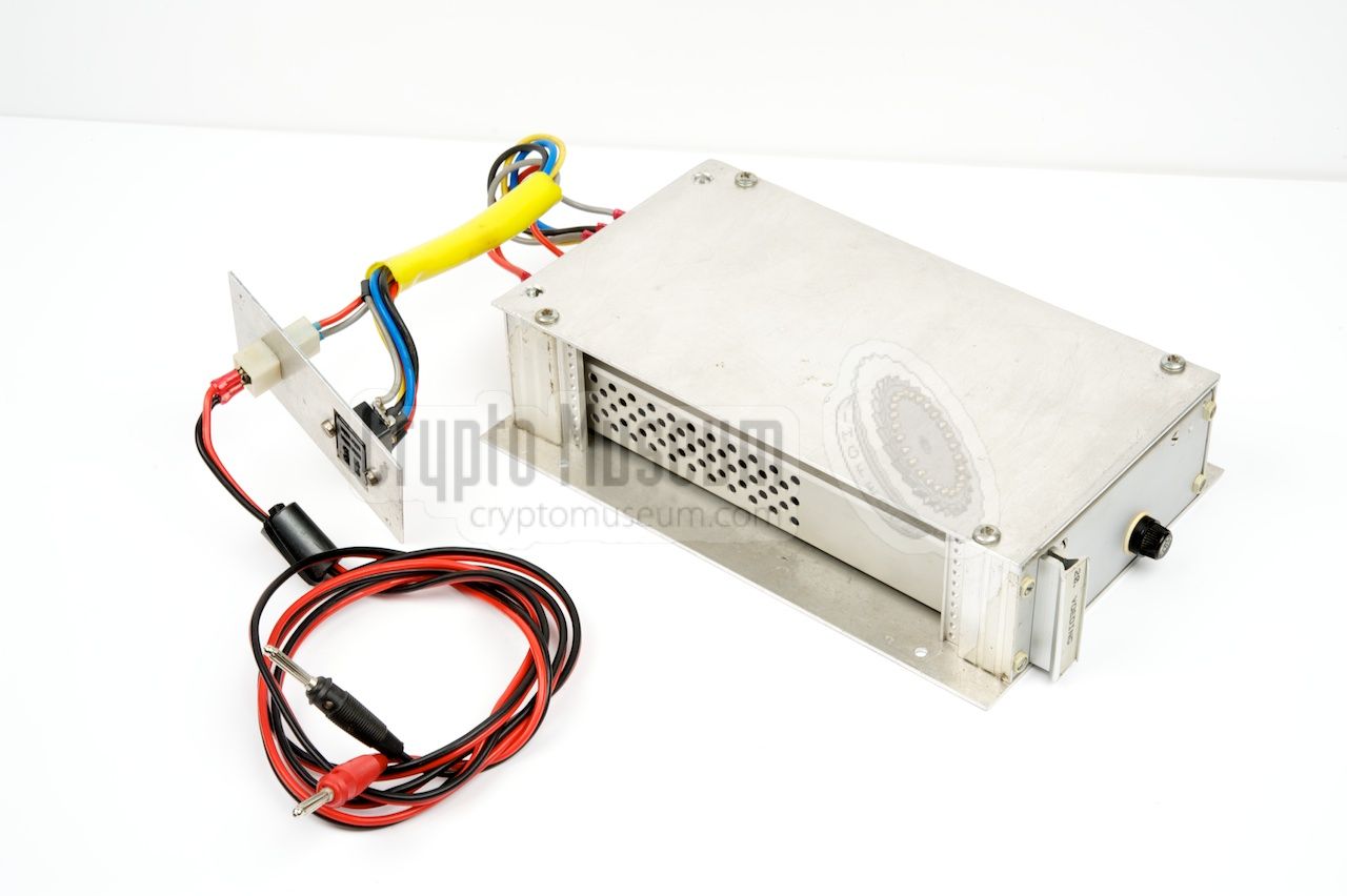
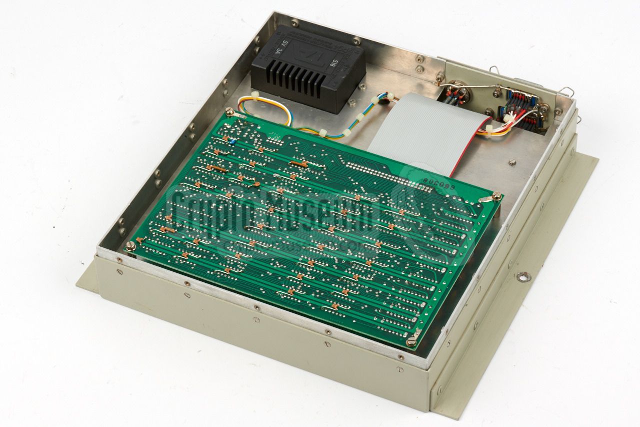
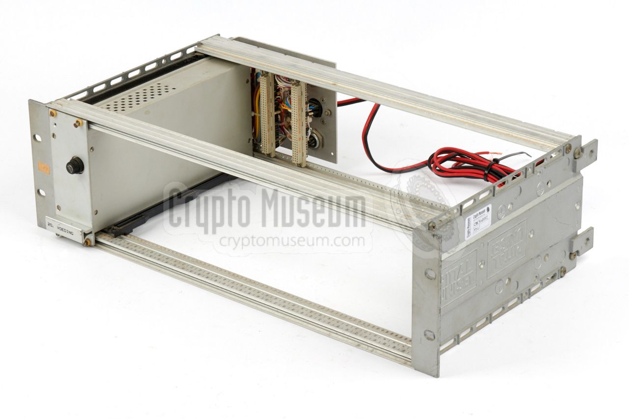
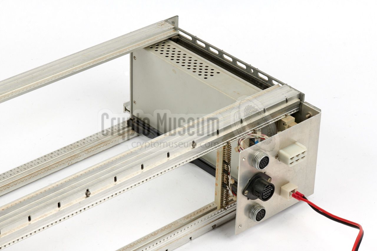
As the RDF option was never used, the extra slots and connectors
were omitted from the PSU that was supplied with the second generation
PAN-1000 receivers that was supplied in 1987.
As a result, the new PSU requires far less space in the trunk of the
car. The image on the right shows the redesigned PSU, which is housed in
a simple aluminium enclosure that was mounted behind the main unit.
A small aluminium panel holds the sockets for connection to the vehicle
battery (2-pin) and the main unit (8-pin Jones).
The PSU was wired directly to the car battery.
|
|
|
|
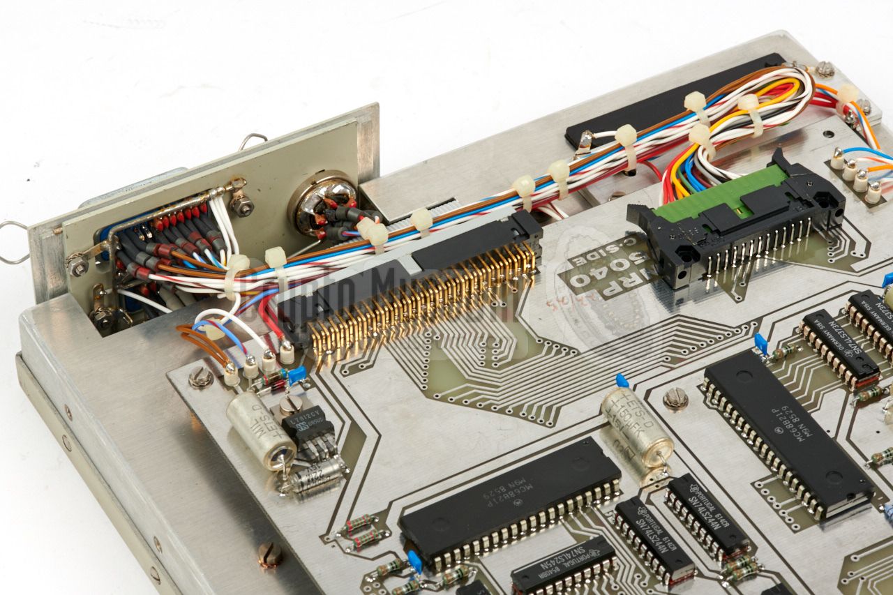
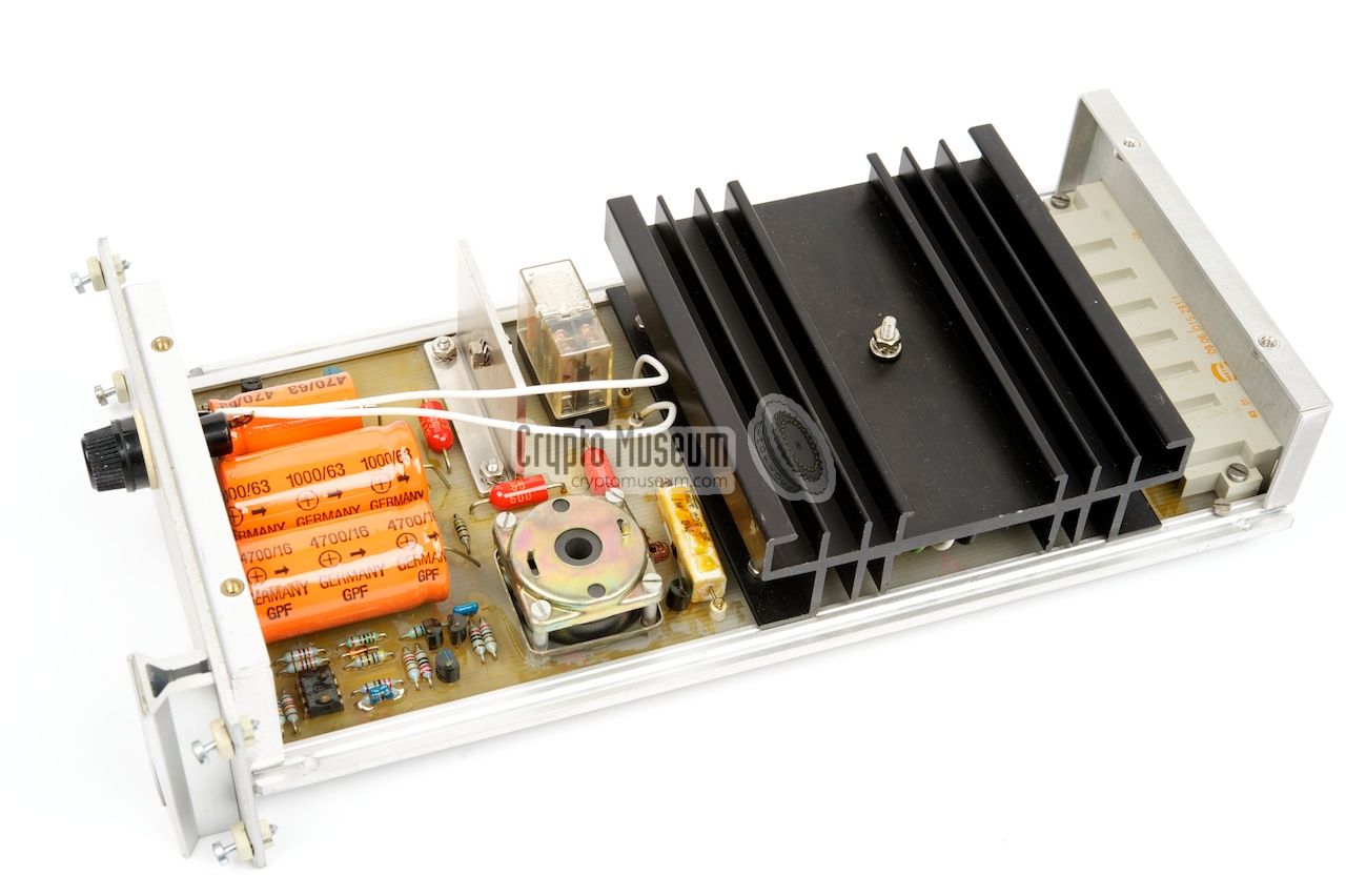
Inside the PSU
is a simple DC-DC voltage converter, built from discrete
components. It contains a 55 kHz square-wave generator that is built around a
CA3140 OpAmp, and provides stable +15V and -12V voltages for display
and A/D converter.
A relay switches the raw +12V to the main unit.
|
|
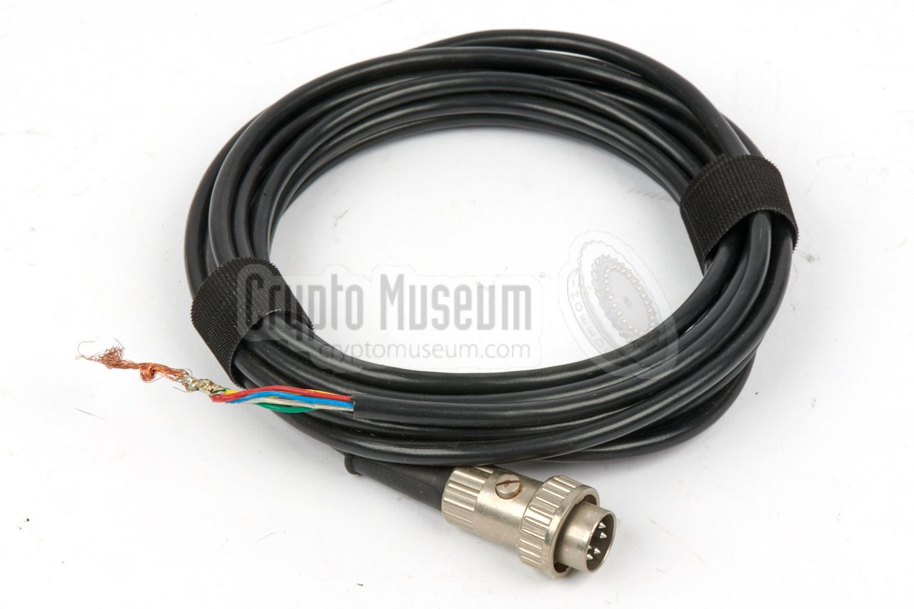
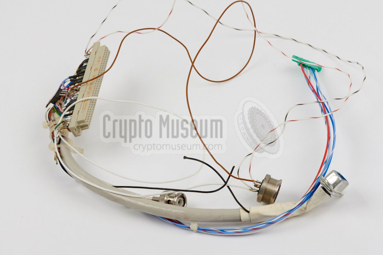
The PAN-1000 came with a full set of cables for installation in a regular
car. A multi-wire cable with a 7-pin DIN plug at either end
connects the main unit (RX) to the display interface (INT). This cable
carries power (15V and -12V) and full-duplex serial data at
a speed of 76800 baud.
|
The cable is long enough to run from the trunk to the glove
compartment at the dashboard, in which the display interface (INT) is installed.
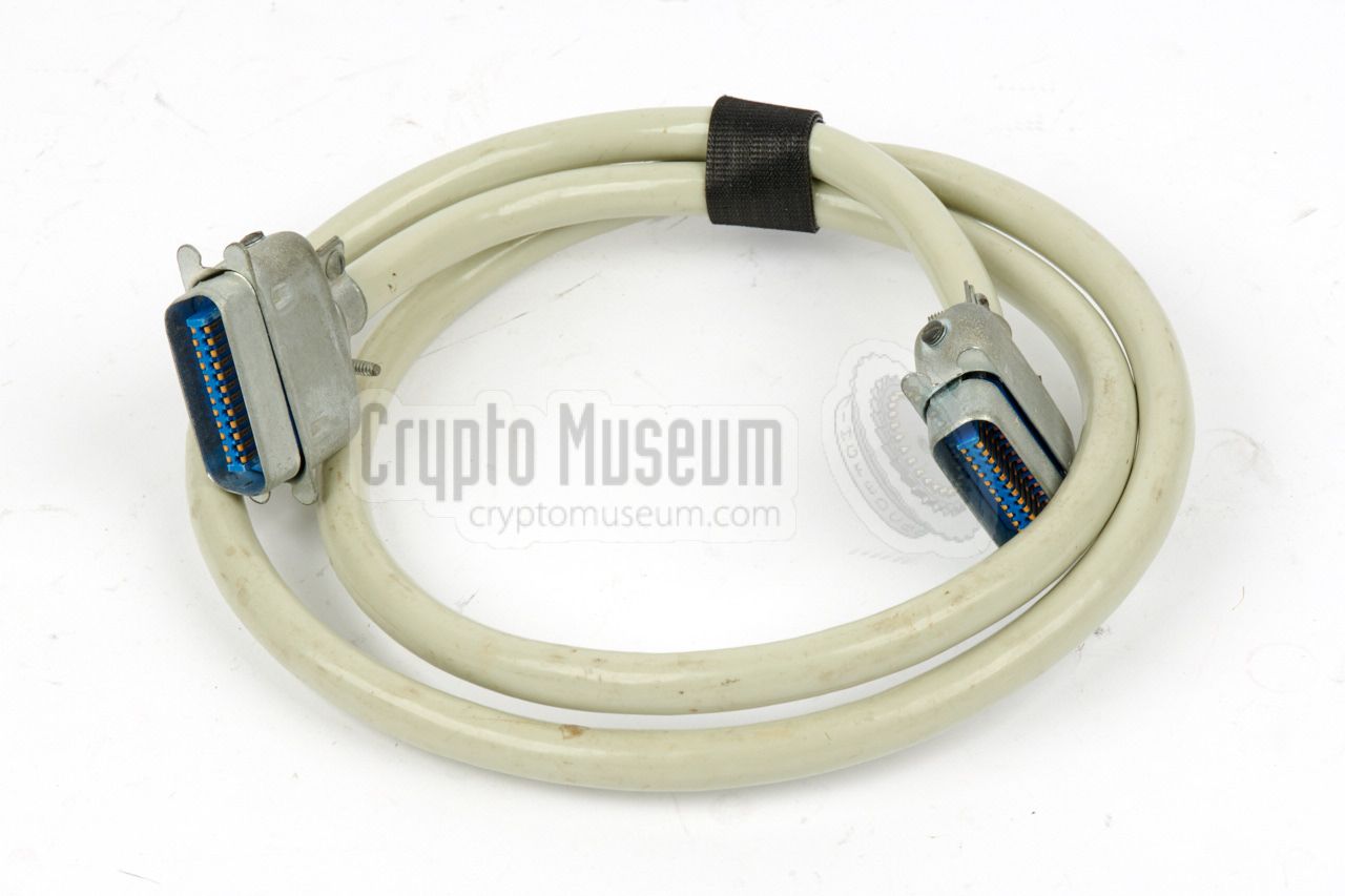
Another long 14-wire multi-cable
connects the main unit (RX) to the
remote control unit (RCU) between the front seats. This cable carries the
audio signal and the ON/OFF line, allowing the receiver to be turned
on remotely from the RCU.
A shorter 24-wire multi-cable
connects the RCU to the display interface,
allowing it to keep the main unit updated with the state of the controls.
|
|
|
|
The image above shows the 24-wire RCU/INT cable.
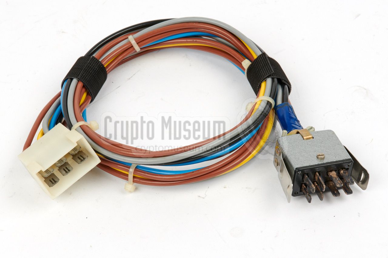
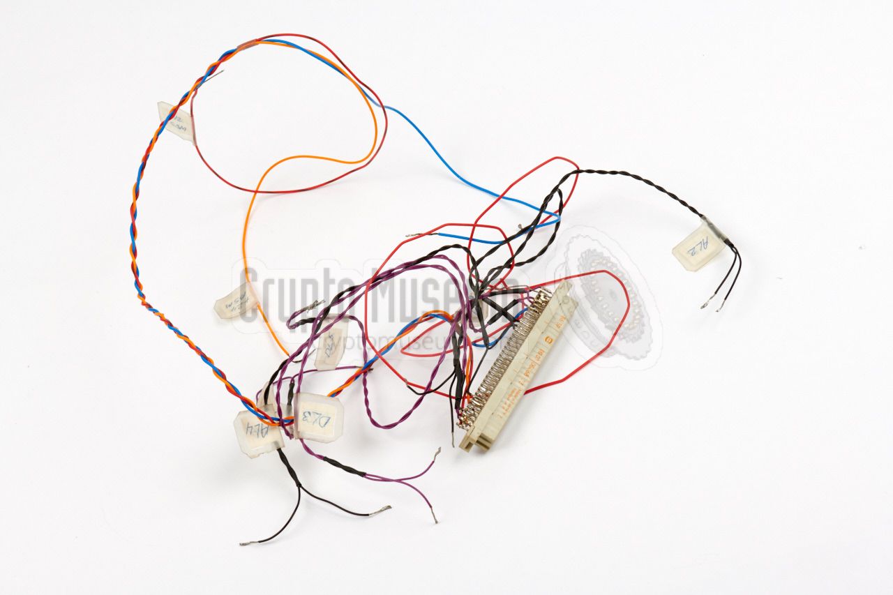
A thick multi-coloured 6-wire cable is used to connect the main unit (RX)
to the external power supply unit (PSU). Depending on the type of PSU and
the type of socket on the main unit, one of three different power cables
was supplied.
|
|
The first generation of PAN-1000 receiver had provisions for the connection
of an (optional) doppler
radio direction finder (RDF), which is why the
power supply module (PSU) was housed in a full width 19" rack. Two additional
cards could be installed in the rack, and two additional multi-wire cables
were supplied for connection to the main unit
and to the external installation.
Although all cables and interfaces were present, it is unlikely that this
option was ever used.
|
The PAN-1000 does not have an internal speaker. Instead, an external
speaker must be connected to the 5-pin 270° DIN socket at the rear
of the remote control unit (RCU).
In most cases a simple small speaker was used, such as the one shown in
the image on the right. It is manufactured by the German manufacturer
Peiker and was commonly supplied with two-way radios and early car phones.
The one shown here was branded 'PTT' as it was also used by the Dutch
(state-owned) telecom provider with the first generation of car phones.
|
|
|
Each PAN-1000 system came with a full set of operational and technical
documentation, divided over two blue plastic binders. The manual contains
operating instructions as well as full circuit descriptions and circuit
diagrams.
As there are some differences between the first and second generation
PAN-1000 units, the manual for the first 10 units is different from the
one supplied with the later ones.
➤ Download the newer manual
|
|
|
|
The history of the PAN-1000 receiver starts in the early 1980s,
a time when The Netherlands was undergoing a recession and
was plagued by an increasing number of clandestine radio and TV
stations, commonly known as 'pirates'. At the time,
the Radio Monitoring Service (RCD),
responsible for confiscating illegal transmitters,
was heavily understaffed and had virtually no budget.
|
When the current State Secretary of Transport – Mrs. Smit-Kroes [4] –
visited the headquarters of the RCD in Nederhorst
Den Berg (Netherlands) at the end of 1980 or the beginning of 1981, the
managing director, Daan Neuteboom, expressed his concern about
the lack of staff and budget.
When Mrs. Kroes unexpectedly asked him how many extra employees
he wanted, he stared at the ceeling for a moment and answered:
"Fourty, Madam State Secretary". Although he probably wasn't expecting
to get them, she replied: "You will get your fourty men, Mr. Neuteboom!" [2].
|
|
|
|
From then on, a seemingly endless line of new employees entered service.
At the same time, it was decided to professionalize the department and
develop a state-of-the-art receiver.
A small committee was assembled to define the initial
functional specification, using an existing
Hans Plisch receiver as a starting point.
It would have to be a panoramic receiver with an operational frequency
range from 100 kHz to 1GHz, and it had to fit inside a standard car.
The new receiver – that would later become known as PAN-1000 – would be
developed and built in small quantity by the
Dutch Radar Laboratory –
Nederlands Radar Proefstation (NRP) –
in Noordwijk (Netherlands).
|
Development of the receiver at the NRP started around 1983.
Apart from the extreme technical specifications, several other problems
has te be solved before it could be taken into production.
The first problem was the panorama display. It had to be fitted on the
dashboard of a car, so it could not be too deep.
LCD screens were small
enough, but were way too slow at the time
to give a real-time representation of the frequency spectrum.
This problem was solved by using an early type of
Electroluminescent display (ELD)
produced by the Japanese company Sharp [7].
|
|
|
|
Electroluminescent displays (ELDs) are known today as Plasma Displays.
At the time they were only available as monochrome displays.
On the selected display the image was show in a yellow colour known as
amber.
Integrating it in the design wasn't for the faint of heart. Two additional
large PCBs – both supplied by Sharp – had to be added in order to display
text and graphics.
|
Another problem was that the receiver had to be controlled
by the operator whilst driving the car. This means that a special remote
control unit had to be developed.
For safety reasons, it had to be fully intuitive and the operator had to
be able to identify each knob without looking at it.
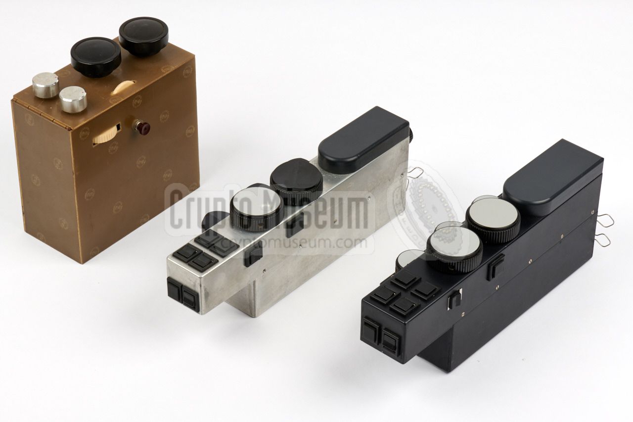
Cor Moerman [3], one of the law enforcement officers of the RCD, came up
with a mockup of a possible design – made from junkbox parts –
to explain the idea.
After several redesigns and improvements, it evolved into the elegant
remote control unit that was supplied with the receiver.
|
|
|
|
The image above shows the mockup and the final design side-by-side.
The final one is designed in such a way, that it can be mounted between
the front seats, aside the handbrake. The operator could rest the
palm of his hand on the rounded pad, and operate the controls with his fingers.
|
It was decided to use a modular design and implement the receiver as
a set of plug-in units at extended Eurocard size (160 x 100 mm, plus the
connector), so that it could be housed inside a readily available 19" rackmount
enclosure.
It turned out that two full-width eurocard cases were necessary.
The power supply unit (PSU) was placed externally, to avoid
radio interference.
The image on the right shows the prototype of the PAN-1000 that was used
at the NRP for hard and software development. It was later also used for
incidental repairs and for firmware upgrades.
|
|
|
|
Finially, in May 1984 the PAN-1000 was ready for
release and the first units were delivered to the RCD.
They were built into the existing intercept vehicles of the day:
a series of Ford Granada and several Peugeot 204 cars.
Production of the PAN-1000 receivers was rather slow, and
the first 10 units were delivered over a period of several years.
In 1987, another 21 units were manufactured.
|
|
Initially, a Radio Direction Finder (RDF) was planned as an optional
expansion for the PAN-1000. For this reason, the PSU was placed in a
separate 19" rack, which had two additional slots for the interface.
Although the NRP developed a prototype of an RDF unit that worked well
with narrowband signals (NBFM), they were unable to make it work reliably
with wideband signals (WBFM).
|
By that time, The Japanese company TAIYO came up with the
TD-L1706 radio direction finder
with EF-353 antenna that worked well with both
narrowband and wideband signals.
As the TAIYO unit could simply be connected to the 10.7 MHz IF output of the
PAN-1000, it was decided to cancel the development of the NRP direction
finder, and order TAIYO units instead.
The TAIYO direction finding units were later used again on the successor
of the PAN-1000: the PAN-2000.
➤ More information
|
|
|
|
Each PCB inside the PAN-1000 is treated with a conformal coating that
protects it from dust and moist. In the late 1980s one of the RCD's vehicles
accidentally ended up in a canal. When it was recovered, the PAN-1000 was
still fully functional, while all other equipment in the car was lost.
|
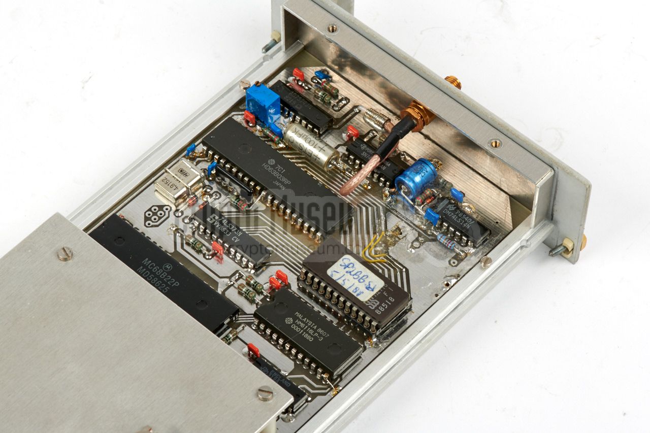
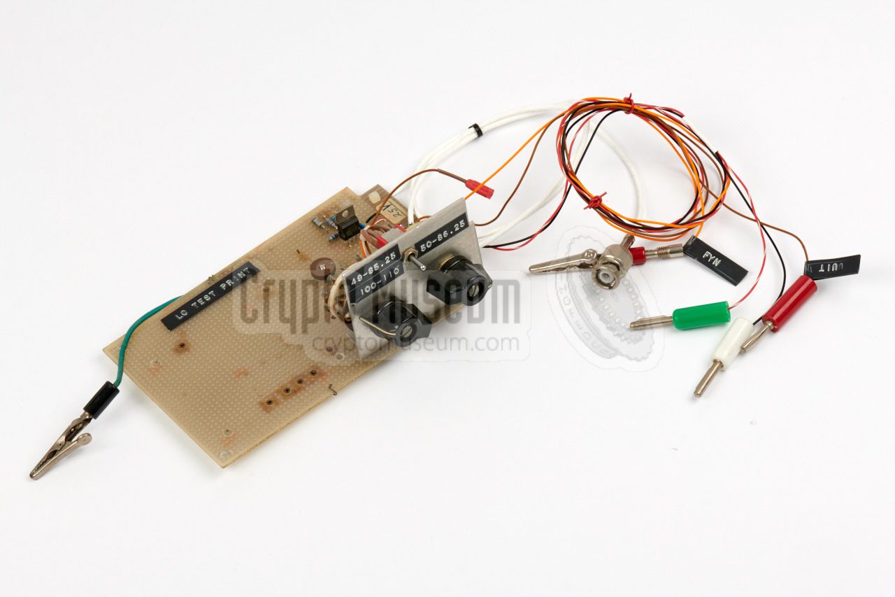
Testing and aligning the individual modules of the PAN-1000 was
extremely complex and not for the faint of heart. Especially the alignment
of the two free-running oscillators in synthesizer modules 17 and 18 was
tough, as its inductors had to be adjusted within very narrow limits [8].
Several tools, or jigs, were developed at the NRP for the alignment
of the various modules of the PAN-1000, such as the one shown in the image
on the right, which was probably used for testing a synthesizer outside of
the receiver's enclosure, connecting directly to the PCB's wide DIN socket.
|
|
|
|
|
Radio Monitoring Service (RCD)
|
|
|
The RCD
was the Dutch Radio Monitoring Service
(Radio Controle Dienst),
responsible for tracing radio and TV interference, and for enforcing
the Telecom Law.
The PAN-1000 was developed in the early 1980s,
when the Netherlands was flooded with radio and TV pirates.
Although the name of the organization has been changed several times
over the years, it is often still called RCD by the public.
The agency is currently known as RDI.
➤ More about the RCD
|
|
|
|
|
Dutch Radar Laboratory (NRP)
|
|
|
The NRP was the Dutch Radar Test Station (Nederlands Radar Proefstation)
in Noordwijk. It was established by Mr. J.M.F.A. (Joop) van Dijk
shortly after WWII, on 7 July 1947, in an attempt to bring The Netherlands
up to speed with the wartime developments in the field of RADAR.
In the years that followed, the NRP was involved in development and consultancy
in the field of RADAR, navigation, sensors, communication equipment and
communication systems in general. In the early 1980s the NRP was asked to
develop the high-end PAN-1000 intercept receiver for the RCD.
➤ More about the NRP
|
|
|
|
|
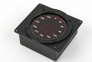
Field strengh indicator
NRP-FS
|
|
|
Alongside the PAN-1000 intercept receiver (see above), the NRP also
released this small portable field-strength indicator that was used
by the law enforcement officers to pinpoint the location of
clandestine transmitter at very close range.
This unit has a built-in frequency counter that could be enabled
temporarily by the user,
to quickly determine the frequency of the signal.
➤ More information
|
|
|
|
Below is the wiring for the most important connectors on the device.
It is assumed that the multi-wire cables (with Amphenol connectors) –
that connect the various units together – are present and operational.
If the pinout of sockets for
these cables is needed, please refer to the
service manuals
[A].
Furthermore, there are several additional sockets on the original
(rack-mounted) PSU of which the function is currently unknown.
They were probably reserved for an RDF unit.
|
|
A 2-pin AMP connector is used for connection of the PAN-1000 to a 12V
DC source, such as the battery of a car. The plugs has an index to prevent
it from being inserted the wrong way around. If a suitable plug is missing,
it is also possible to use common single AMP-plugs, but please check the
polarity before applying power.
|
Red 10.6 — 15V Grey Ground (0V)
|
|
|
An 6-pin AMP socket is present at the rear of the receiver rack (RX). The same
socket is present on the power supply unit (PSU). The image below shows the
pinout of this connector when looking into the socket. Note that later versions
of the PSU and/or the receiver rack, have an 8-pin Jones connector in this
place.
|
Brown 10.6 — 15V Yellow 15V Grey GND Brown 10.6 — 15V Blue -12V Black ON/OFF
|
|
|
The Control Unit (CU) has a 5-pin 180° DIN socket
at the right side, just behind the SQUELCH control.
This sockets is wired for MONO recording and is completely
isolated from the receiver, by using a 1:1 transformer.
It supplies AUDIO, independent from the VOLUME control,
at a line level of 0dB into a 600 Ω load.
Pinout is as follows (looking into the socket):
|
- Audio out (0dB into 600Ω)
- Ground
- not used
- not used
- not used
|
|
|
The connection for the speaker is at the rear of the CU,
where also the connections to the display unit and the
receiver are. The audio amplifier can deliver 2W into a
4 Ω speaker.
The speaker connection is a 5-pin 240° socket
with the following pinout:
|
- Audio out (speaker)
- not used
- Ground
- not used
- not used
|
|
Device Monitoring and surveillance receiver Purpose Locating clandestine radio transmitters and sources of interference Model PAN-1000 Type Digital synthesizer double/triple conversion superheterodyne Manufacturer Dutch Radar Laboratory (NRP) Users Dutch Monitoring Service (RCD), Dutch Foreign Office (BuZa) Years 1983-1987 Frequency 100 KHz - 1 GHZ Bands 6 ➤ More Tuning Continuously with rotary dial (250/rev), coarse with push-buttons Spacing Depending on MODE and frequency band (see brochure) Clarifier More than one frequency step (always available) Resolution 1 kHz (clarifier offset not shown in display) Memories 6 (volatile) 1 Noise figure < 9 dB IP3 > 5 dBm (f < 30 MHz), > 0 dBm (f > 30 MHz) Modulation USB, LSB, AM, NBFM, WBFM, CW (in position USB or LSB) Stereo Indicator 'S' shows on display when detecting pilot tone Bandwidth ➤ Crystal filters Squelch With NBFM and WBFM only AF output 2 Watts into 4Ω speaker Recording 1mW, 600Ω, fixed level Power 12V DC Quantity 30-40
|
-
Not retained over a power cycle.
|
- 0.1 - 31.25 MHz
- 31.25 - 62.50 MHz
- 62.50 - 125 MHz
- 125 - 250 MHz
- 250 - 500 MHz
- 500 - 1000 MHz
|
USB 2.4 kHz LSB 2.4 kHz AM 5 kHz NBFM 12 kHz WBFM 100 kHz - using LSB/USB
|
0.1 - 31.25 MHz 0.3, 1 or 3 MHz 31.25 - 62.5 MHz 1, 3 or 10 MHz 62.5 - 500 MHz 1, 3, 10 or 30 MHz 500 - 1000 MHz 1, 3, 10, 30 or 100 MHz
|
|
Below is a complete list of the various modules of the PAN-1000.
Modules 1 thru 19 are part of the Main Unit.
Module 20 is the PSU, which is housed in a separate 19" rack.
The other modules are available as separate units.
Click here for a detailed description of each module.
|
- Input selector
- Converter 500-1000 MHz
- Converter 250-500 MHz
- Converter 125-250 MHz
- Converter 62.5-125 MHz
- Converter 31.25-62.5 MHz
- Converter 0.1-31.25 MHz
- 50 MHz Selector Unit
- IF Converter
- IF Amplifier and Demodulator
- Logarithmic Amplifier
- Mixer Panorama Display
- Sweep Synthesizer
- Microprocessor µPS
- 240/360 MHz Synthesizer
- 400-690 MHz Synthesizer
- 50-86.25 MHz Synthesizer
- 49-85.25 MHz Synthesizer
- 100-110 MHz Synthesizer
- DC-DC Converter (PSU)
- Remote Control Unit (RCU)
- Display Interface Unit (INT)
- Panorama Display (DSP)
|
|
AF
|
|
Audio Frequency
|
|
DSP
|
|
Display
In this context used for the display.
Not to be confused with the current abbreviation DSP
which means digital signal processor.
|
|
HF
|
|
High Frequency
|
|
IF
|
|
Intermediate Frequency
|
|
INT
|
|
Interface
In this context used for the
display interface unit.
|
|
NRP
|
|
Nederlands Radar Proefstation
Dutch Radar Test Station in Noorwijk (Netherlands). Established in 1947 and renamed to
CHL (Christiaan Huygens Laboratorium) in 1993. Now located in Katwijk (Netherlands).
➤ More
|
|
RADAR
|
|
Radio Detection and Ranging
|
|
RCD
|
|
Radio Controle Dienst
Radio Monitoring Service of the Dutch Post Office (PTT) from 1975 to 1989.
Later renamed to Agentschap Telecom (AT) and now part of
the Ministry of Economics.
➤ More
|
|
RCU
|
|
Remote Control Unit
In this context used for the black control device by which the PAN-1000
is operated.
|
|
uP
|
|
Microprocessor
Also written as µP. In this context used to identify any of the
three microprocessors that control the operation of the PAN-1000
(µPS, µPC and µPD).
➤ More
|
-
Manual reproduced here by kind permission of the NRP Legacy [9],
|
- Nederlands Radar Proefstation BV, Panorama Ontvanger 0,1-1000 MHz
Service Manual (Dutch) for serial numbers 11 to 32. February 1987. 1
- Anonymous former Investigator of the RCD
Interview at Crypto Museum, May 2011.
- Cor Moerman, former Investigator of the RCD
Interview at Crypto Museum, January 2013.
- Wikipedia, Neelie Kroes
Dutch State Secretary for Transport from 28 December 1977 to 11 September 1981.
Visited January 2013.
- Cor Moerman, Mockup of PAN-1000 Control Unit
Object kindly given on loan by Cor Moerman for the purpose of this page.
Museum Jan Corver, January 2013.
- CHL Netherlands BV, Successor of the Nederlands Radar Proefstation (NRP)
29 January 2013. ➤ About NRP/CHL
- Wikipedia, Electroluminescent display
Retrieved April 2018.
- AT/RCD Engineer, Personal correspondence
April 2018.
- Dutch Radar Laboratory (NRP) Legacy
Crypto Museum, February 2016.
|
-
Manual reproduced here by kind permission of the NRP Legacy [9],
|
|
|
|
Any links shown in red are currently unavailable.
If you like the information on this website, why not make a donation?
© Crypto Museum. Created: Tuesday 15 January 2013. Last changed: Monday, 25 May 2026 - 07:44 CET.
|
 |

|
|
|