|
|
|
|
|

|
|
RDI PAN-6000 → ← PAN-2000
The system is built around an EB-200 receiver
from Rohde & Schwarz, and features a panoramic FFT
spectrum display, that is driven by a central processing unit in 19"
enclosure. Since the system was intended for use inside a vehicle,
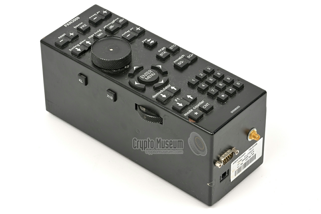
an intuitive remote control unit (the console)
is used to control all functions. It can be
placed conviently between the two front seats of the car, so that it
can be controlled whilst driving.
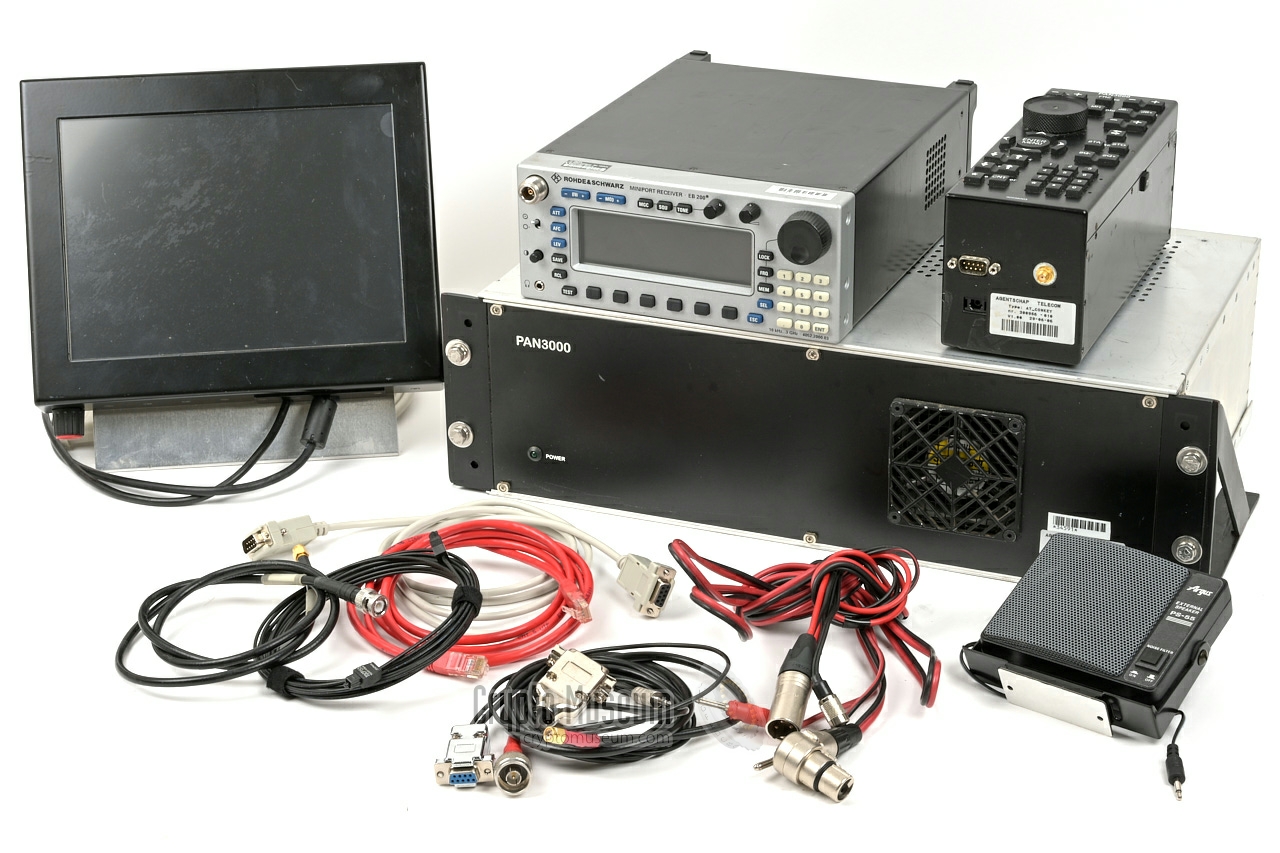
The image on the right shows a complete PAN-3000 installation, comprising
a main unit, EB-200 receiver, console,
display and accessories.
|
|
|
The PAN-3000 can be extended to a full radio direction finding
(RDF) system by adding the EF-353 antenna from its predecessors. This
antenna (or another DF-antenna for that matter) can be controlled directly
from the main unit. Furthermore, the system could be fitted with
a frequency counter (also from its predecessors) that allowed it to lock
instantly onto a nearby RF signal.
Following the success of the earlier PAN-1000 and
PAN-2000, it was decided to commission the development
of the PAN-3000 to an external contractor. Development of the system started
in 2005 as a joint effort of two companies: Pree-e-rf-tech and Rena,
both from the Netherlands. After delivery and approval of the first
prototype, 15 complete units were built and delivered in 2006.
In 2013, the flat panel video screen was replaced by an Android tablet.
In 2016, an electronic compass was added to the digital map, but this was
less successful than anticipated [1].
In 2016, ten years after the inception of the PAN-3000, it became
increasingly difficult to maintain the current system and keep it up-to-date
with respect to modern features and digital radio signals. It was therefore
decided to commission a commercial party with the development of its
successor: the PAN-6000. However, as the prototype did not
meet the expectations, the project was cancelled and the RDI
decided to develop the PAN-6000 itself. It was released in 2025.
|
 |
-
The name PAN-3000 is derived from its predecessors PAN-1000
and PAN-2000, in which 'PAN" is short for 'Panoramic' and
'3000' is the highest frequency in MHz (3000 MHz). The successor is the
PAN-6000.
|
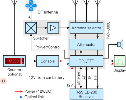
The diagram below shows how the various parts of the PAN-3000 system
are interconnected. At the heart of the system is a
Rohde & Schwarz (R&S) EB-200 receiver and a purpose-built
CPU (the main unit). The latter is responsible for controlling
the EB-200 — which is usually mounted in the trunk of the
vehicle — through its Ethernet interface. The entire system
is controlled from a compact Console that can be mounted
in a convient place to the right of the driver's seat.
To avoid radio interference, the Console is connected to the
main unit via an optical fiber link (TOSLINK).
Several antennas can be connected to the main unit, including
a set of direction finding antennas; all under software control.
In practice, the PAN-3000 was often used in combination with the
EF-353 antenna of the former PAN-2000 and
PAN-1000 systems, albeit without its controler.
The signal from the antenna(s) is first passed through an
adjustable attenuator, and then delivered to the antenna input
of the EB-200 receiver. The IF-output of the EB-200
(WBIF) is then passed to the IF-input of the main unit.
The speaker output of the EB-200 is also pased to the
main unit.
Video from the CPU plug-in unit is delivered in digital form to
an external flat-panel VGA monitor, via an extended DVI cable.
The complete system is powered from a single power cable, that takes
the required 12 V/DC directly from the vehicle's battery, into
the main unit. From there it is distributed to all other
devices that require 12 V (console, EB-200 receiver
and video display).
|
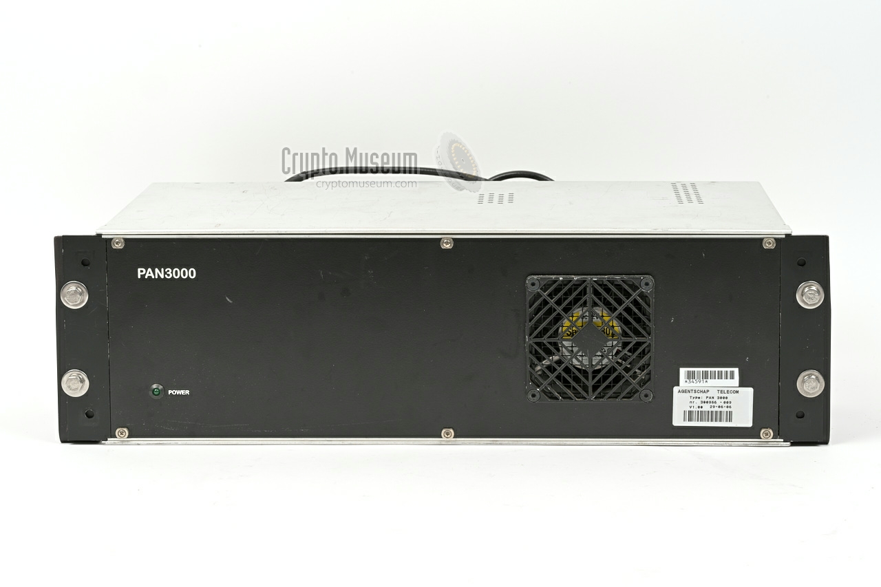
At the heart of the system is the 19" 3U enclosure shown in the
image on the right. It houses the central processing unit (CPU)
that is responsible for showing the FFT display, controlling the
EB-200 receiver and interfacing the console.
It is proprietary-built for the PAN-3000 and runs Linux on a
Kontron CP-306-V-8HP CPU-module.
All other parts of the system are connected to the CPU, including the
incoming and outgoing 12 V/DC power lines.
When present, the CPU also controls the direction finding
antennas.
|
|
|
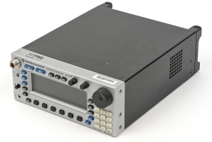
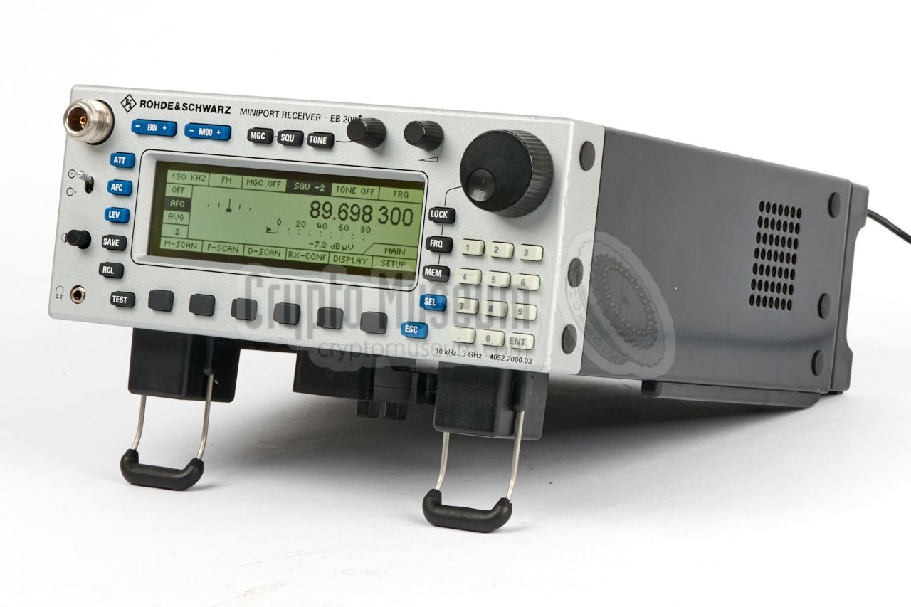
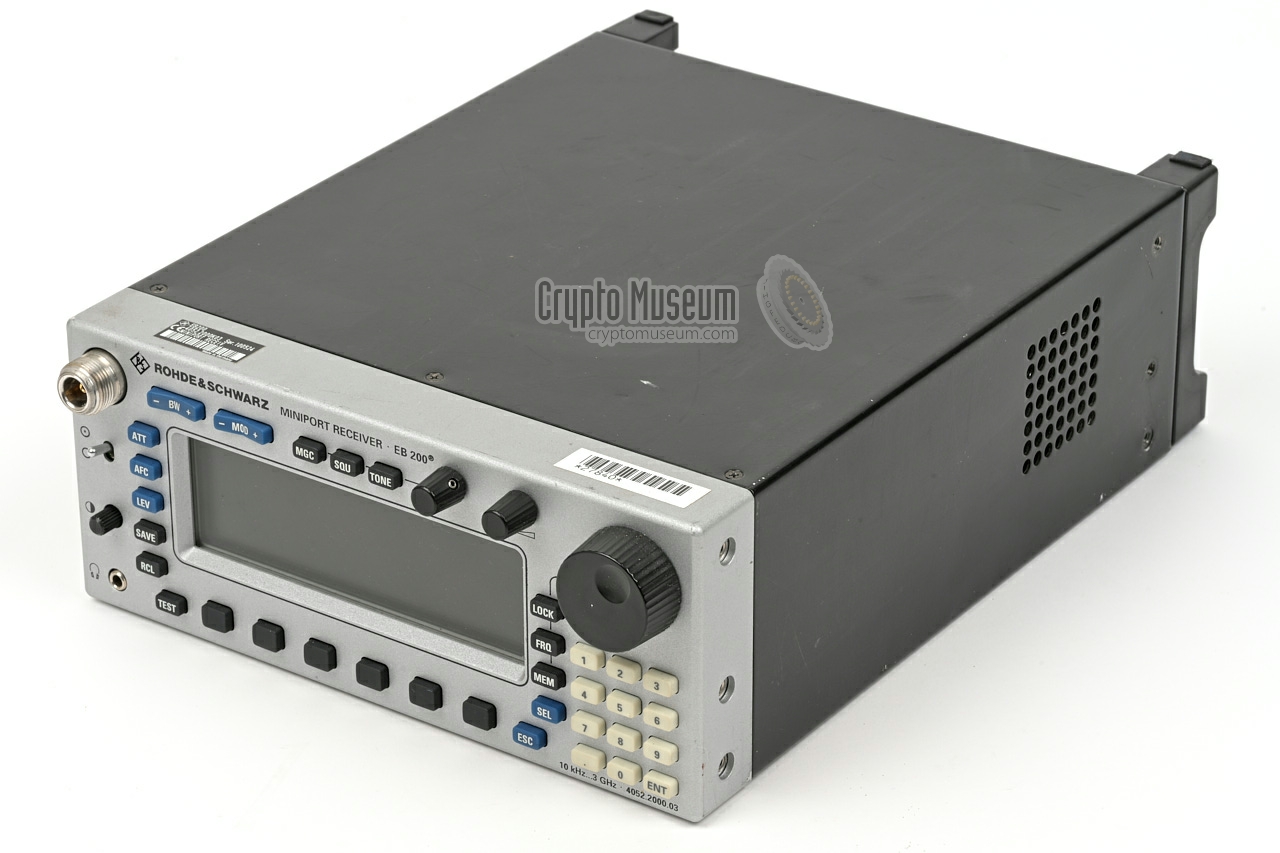
The actual receiver was a Rohde & Schwarz EB-200
portable monitoring receiver, that covers the 10 kHz — 3 GHz
frequency spectrum. It has a maximum IF bandwidth span of 10 MHz.
For remote control, it has the (optional)
Ethernet expansion card installed.
The device was modified by the AT in several ways, to give it
a more uniform performance over the entire frequency range and
bandwidth.
➤ More information
|
|
|
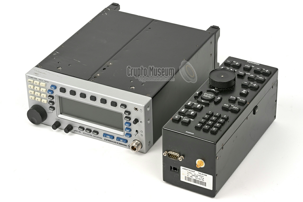
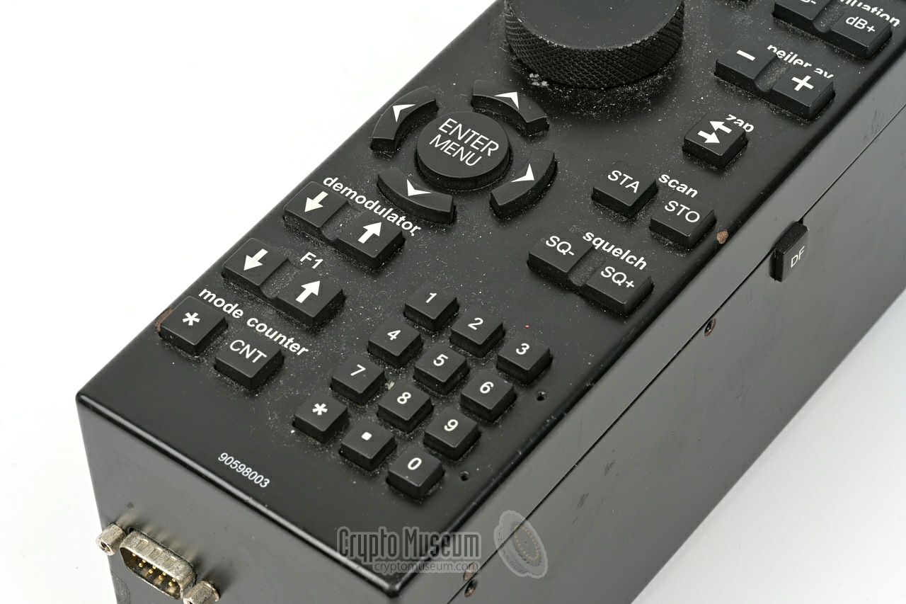
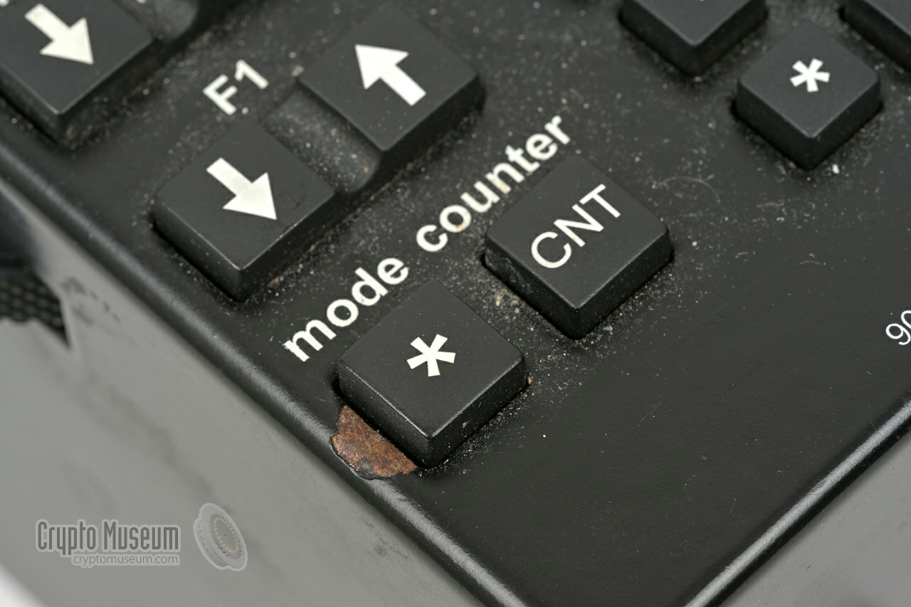
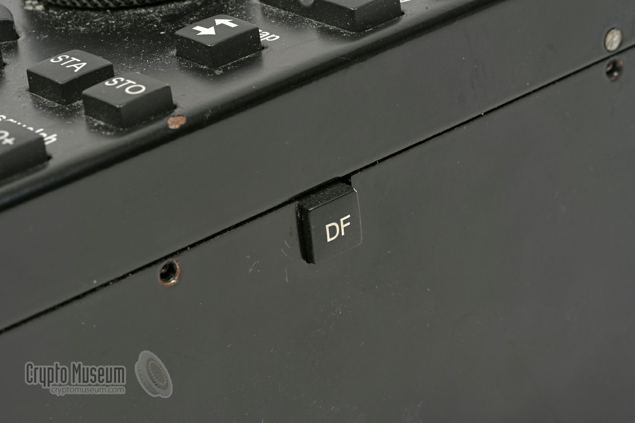
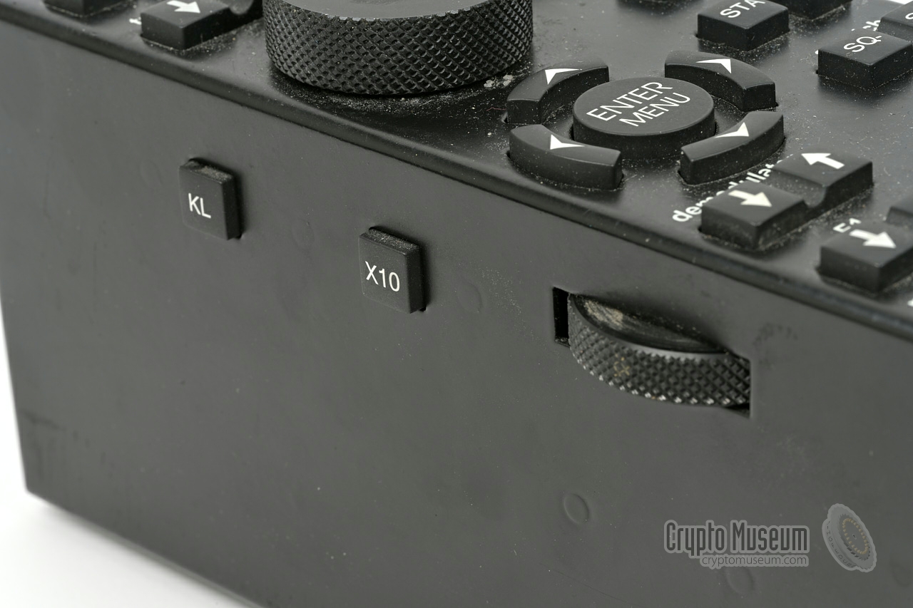
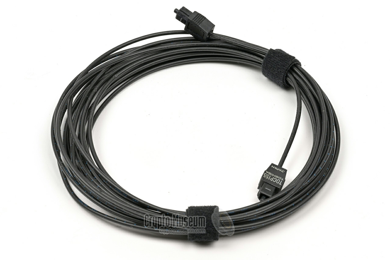
All functions of the PAN-3000 are controlled from the console
shown in the image on the right. It is connected to the main unit
via a DE-9 power cable, and a TOSLINK optical fiber that carrier the
digital signals. This is done to avoid radio interference (RFI) from the
device itself.
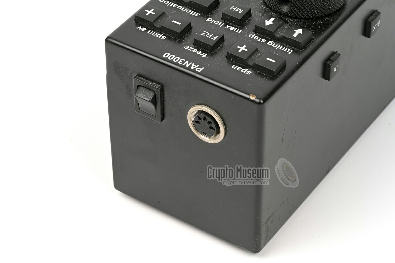
The console also holds the main power switch.
At the front is a socket for connection of an (optional)
frequency counter.
|
|
|
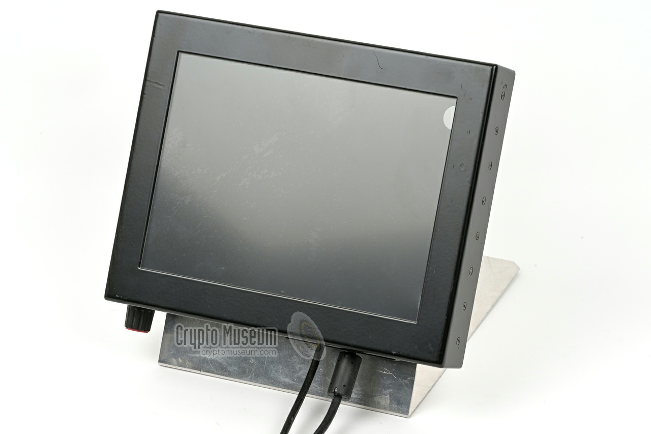
The output of the PAN-3000 is delivered to the mobile VGA
flat-panel colour TFT/LCD monitor, shown in the image on the right.
It is powered by a 12 V/DC source – delivered by the main unit –
and a Digital Visual Interface (DVI) input [2].
The display shows the current settings, but the largest part of the screen
is taken by the FFT-feature, which shows part of the frequency
spectrum around the selected frequency in real-time.
|
|
|
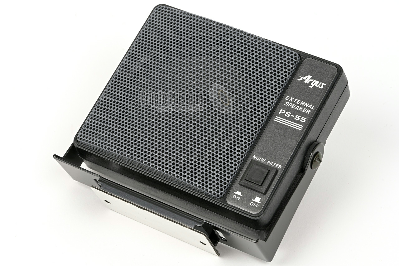
Although the receiver's audio is available from its internal speaker,
this is not convenient, since the EB-200 was usually placed in the
trunk of the vehicle. For this reason, the speaker output of the EB-200
is passed to the main unit via a combined audio cable.
An external speaker, such as the one shown in the image on the right,
is then connected to the main unit. Its volume can be controlled
with the volume-knob at the left side of the console.
|
|
|
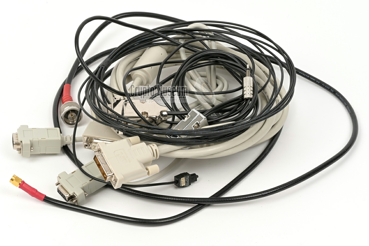
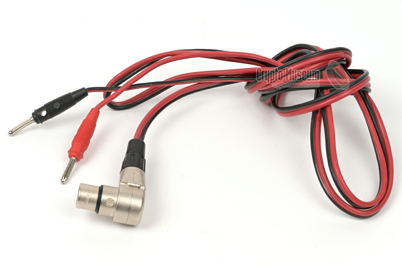
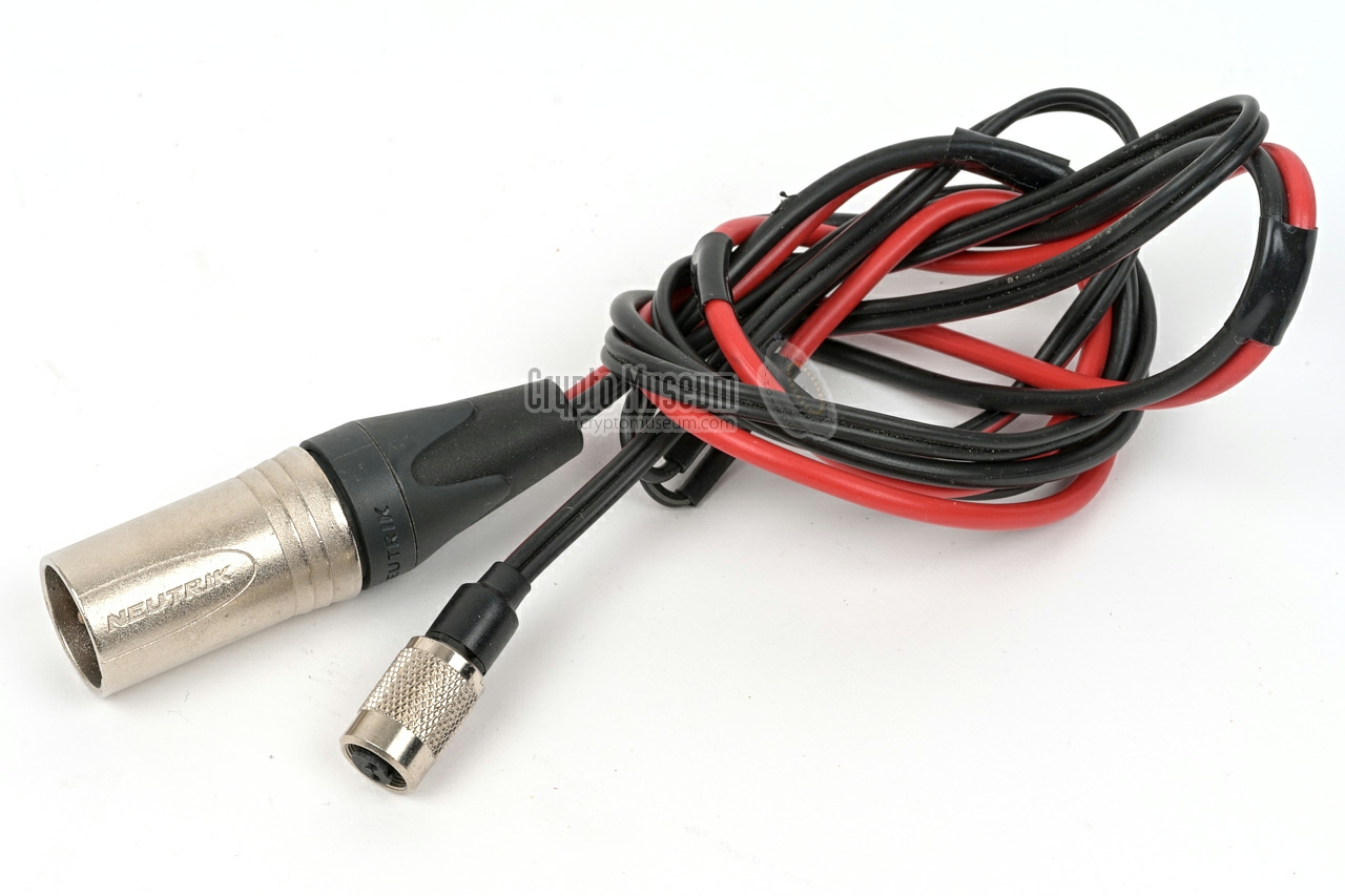
To interconnect all components of a PAN-3000 system,
a wide range of cable types are required, some of which are
proprietary. Included are coaxial cables, power cables,
audio cables and an optical TOSLINK wire. For use in a large
vehicle, some of these cables may have to be extended.
The image on the right shows the cable set that came with the PAN-3000
in our collection. Additional cables are required to connect the
antennas.
|
|
|
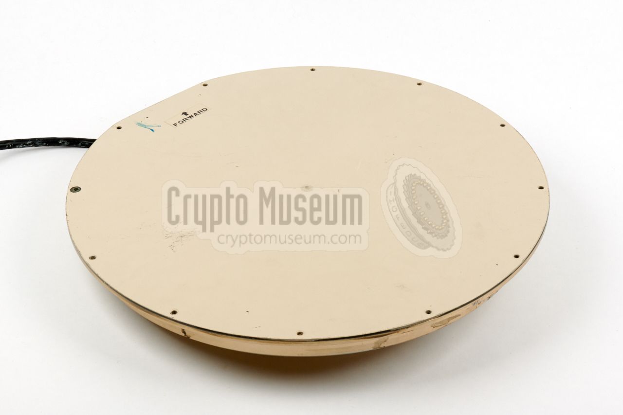
A special flat antenna was used with the TAIYO direction finder.
In consists of four antenna elements in a special arrangement, mounted
in the circular enclosure shown on the right.
The antenna was usually mounted in the top of the car, disguised
as a sunroof, for which it was modified somewhat. Inside the disc is a
fast antenna switcher and a pre-amplifier.
➤ More information
|
|
|
|
|
Frequency counter
CR-3000/C
|
|
|
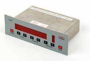
Some intercept vehicles were equipped with the stand-alone frequency
counter shown in the image on the right, which was inherited from the
earlier PAN-2000 system. The device could be mounted in
the regular car stereo bay, and locks onto the strongest
signal in its vicinity.
The 1/100 output of the counter it connected to the
console, allowing the latter to 'grab' the frequency of the
intercepted signal with a single key-press, and tune the PAN-3000 to it.
➤ More information
|
|
|
The main unit (CPU) is housed in a metal 3U 19" rackmount
enclosure. It comprises 10 plug-in units (modules) that are inserted
from the rear and are fitted to an internal backplane, in a fixed
arrangement.
The image below gives an overview of the rear panel of the main unit.
|
| Pos. | Designator | Name | Description |
|
|
| 1 | 90598-013 | Power distribution unit | 12V in/out and power switching |
| 2 | CPCI-PSU-12V | Power supply unit | Internal +5V, +3V3, +12V DC |
| 3 | 90598-010 | I/O | I/O Interface for CPU |
| 4 | 90598-001 | ADC | Analog-to-Digital Converter |
| 5 | CP306-V | Celeron CPU | Linux and firmware on CF card |
| 6 | 90598-008 | Audio I/O | Audio and optical interface for Console |
| 7 | 90598-002 | Peiler | Control of external DF antenna |
| 8 | 90598-007 | Decoder | AF demodulator, stereo decoder and RDS |
| 9 | 90598-005 | MF Filter | |
| 10 | 90598-011 | ATT | Attenuator |
|
The interior of the main unit and the above modules, has not yet been photographed.
|
The PAN-3000 featured on this page, was donated to Crypto Museum on
10 March 2026, by the Dutch Radio Monitoring Service (RDI).
The system was supplied complete with cables and firmware, after the
devices had been decommissioned 2025, following the introduction of the all-new
PAN-6000. It was delivered in operational condition, including cables,
documentation and spare parts. Consequently, there is currently no need
to restore this device.
|
Device Monitoring/surveillance receiver Purpose Locating clandestine radio transmitters and sources of interference Model PAN-3000 Manufacturer Pree-e-rf-tech, Rena User AT (RDI) Year 2006 Operational 2006-2025 Country Netherlands Predecessor PAN-2000 Successor PAN-6000 Frequency 10 kHz — 3 GHz Step see below Bandwidth 5 kHz, 9 kHz, 15 kHz, 120 kHz, 150 kHz IF span 100 kHz, 250 kHz, 500 kHz, 1 MHz, 2.5 MHz, 5 MHz, 10 MHz Firmware 2.4 1 Power 12V/DC Dimensions see below Weight ? Quantity 15
|
-
As the firmware of the main unit (CPU) is subject to third party
copyright, we are not allowed to distribute it.
|
- 1 Hz
- 10 Hz
- 100 Hz
- 1 kHz
- 5 kHz
- 10 kHz
- 12.5 kHz
- 20 kHz
- 25 kHz
- 100 kHz
- 1 MHz
|
Device Main unit (CPU) Purpose Main control and data processing Model PAN-3000 Designator 300956-009 Power 12V DC nominal Dimensions HWD: 139 × 492 × 300 mm Weight 10,140 g
|
Device Communication Receiver Purpose Portable and mobile radio monitoring Model EB-200 Manufacturer Rohde & Schwarz Frequency 10 kHz - 3 GHz Remote Ethernet Dimensions HWD: 88 × 210 × 286 mm Weight 4300 g
➤ More specifications
|
Device Video Display Unit (VDU) Purpose VGA display for PAN-3000 system Model ? Manufacturer ? Country ? Resolution ? Interface DVI Power 12V DC Dimensions HWD: 214 × 264 × 45 mm Weight 3,800 g
|
Device Remote control unit (RCU) Model AT-CONKEY Designator 300956-010 Buttons ? Interface Optical (TOSLINK) Power via DE-9 connector Dimensions HWD: 105 × 92 × 235 mm Weight 2,000 g
|
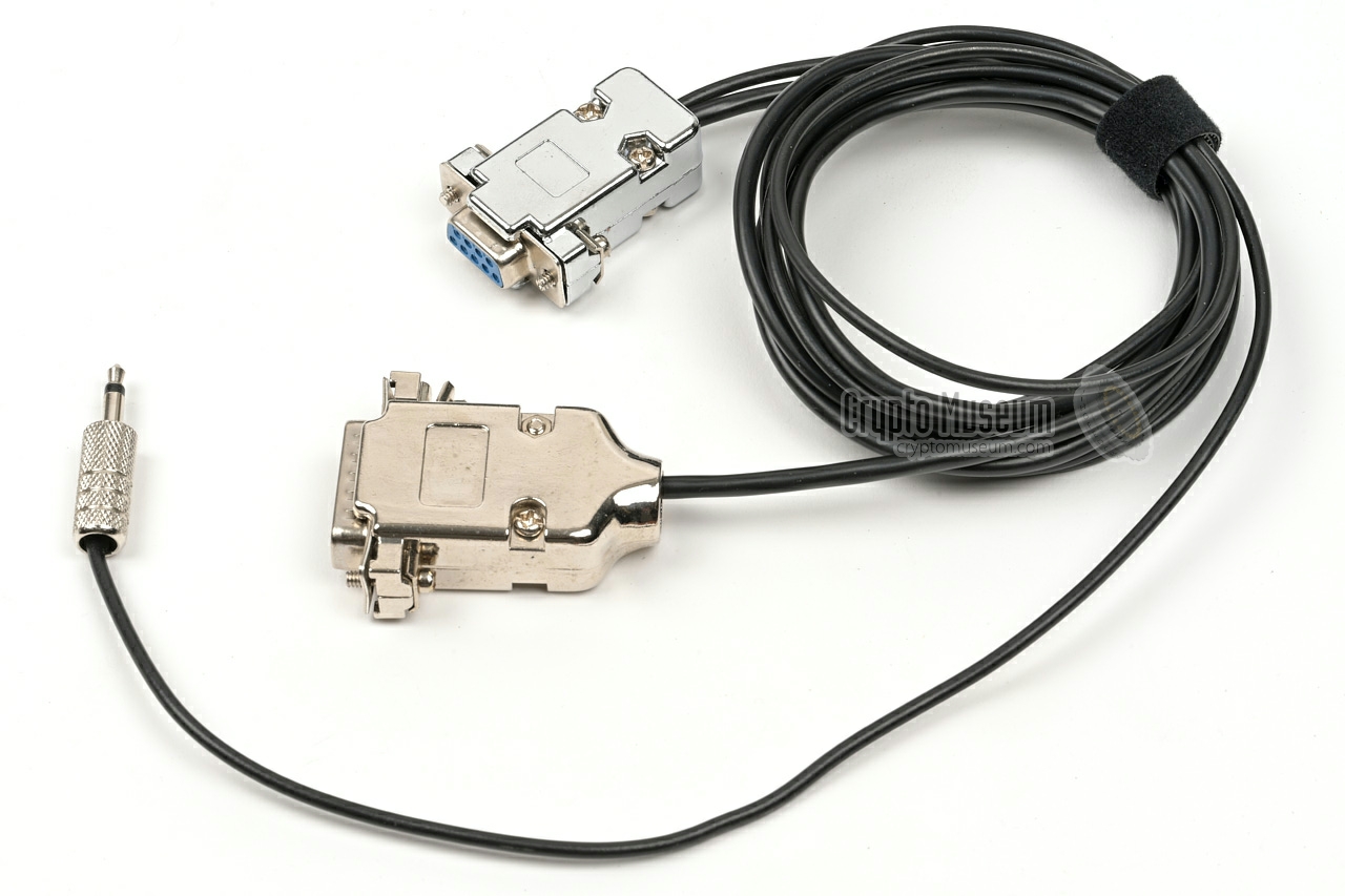
- Serial cable 9-pin DE9 M/F (for remote control)
- Interconnection cable 15-pin DC15/M to DE9/F and 3.5 mm jack
- Optic fibre (TOSLINK) for remote control
- Coax SMA-BNC
- Coax SMA-N
- 4 × coax SMA-SMA (installed on main unit)
|
|
|
|
Any links shown in red are currently unavailable.
If you like the information on this website, why not make a donation?
© Crypto Museum. Created: Wednesday 11 July 2018. Last changed: Friday, 28 August 2026 - 15:50 CET.
|
|

|
|
|
|