|
|
|
|
|

|
|
← IC-R9000
Modifications
- under construction
This page gives a detailed account of the modifications that were made to
the ICOM IC-R9000 receivers that were used by the
Dutch Radio Monitoring Service (RCD, now: AT),
when the device was used in combination with the
PAN-2000 intercept system.
As the RCD/AT used many of its devices in a mobile environment,
it was important to reduce the weight and power consumption.
|
It is estimated that approx. 20 complete PAN-2000 systems were ever made.
After they were decomissioned – sometime between 2005 and 2007 – they were
sold as government surplus, but in many cases the ICOM IC-R9000 got separated
from the main PAN-2000 set, as it was a desired professional (amateur) receiver.
When we obtained our PAN-2000 set (mid-2018), it came with an unmodified
IC-R9000, as the original one had disappeared. Although an unmodifed one
will work with the PAN-2000, it will have a reduced accuracy and performance.
|
|
|
|
As we wanted to restore our PAN-2000 to its original operating conditions,
we decided to modify our IC-R9000, so that it would have the best performance
when used in combination with the PAN-2000 panoramic FFT unit.
This involves altering the AGC circuits, using a different 10.7 MHz IF path,
changing the characteristics of some filters, and adding new connectors at
the rear. All this would not have been possible without the wonderful
assistence from several parties [1].
|
|
All connections of the receiver are located at the
rear panel. A row of
sockets along the bottom edge of the case, provides room for expansion.
Some of the connections are brought out on poor quality CINCH (RCA)
sockets (e.g. IF output), whilst others are missing completely (e.g. CENTER).
|
|
The REMOTE connection was made available on one of the BNC sockets, as it
was found to be more robust than the existing 3.5 mm jack. For connection
to the ICOM REMOTE socket on the PAN-2000, a simple BNC-BNC cable can now
be used. Another socket was reserved for the IF output, which was previously
present on a CINCH socket at the other end of the rear panel (on most
receivers the IF signal was fed out over a fixed coaxial cable.
The third socket was reserved for the signal from the discriminator meter,
here known as the CENTER meter (or: CM OUTPUT).
|
|
|
Mains power supply removed
|
|
|
|
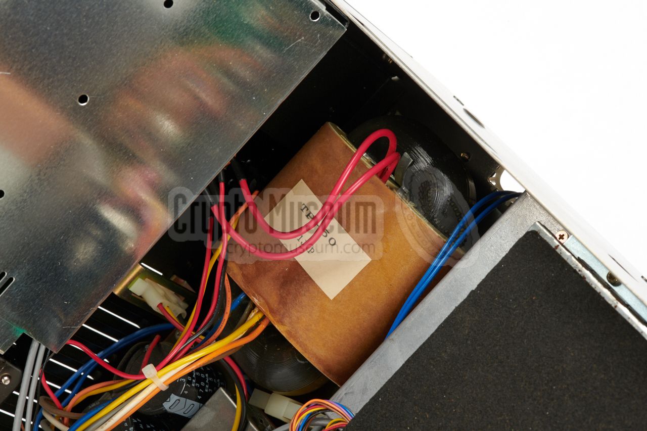
As the IC-R9000 was commonly used in a mobile environment, the internal
mains PSU was not used. As it is rather heavy — the PSU is built around
a conventional transformer — is was often removed in order to reduce weight.
Note that this was not the case for the receivers that were used in a
(semi) stationary setup, such as the ones that were used in fixed
monitoring stations.
|
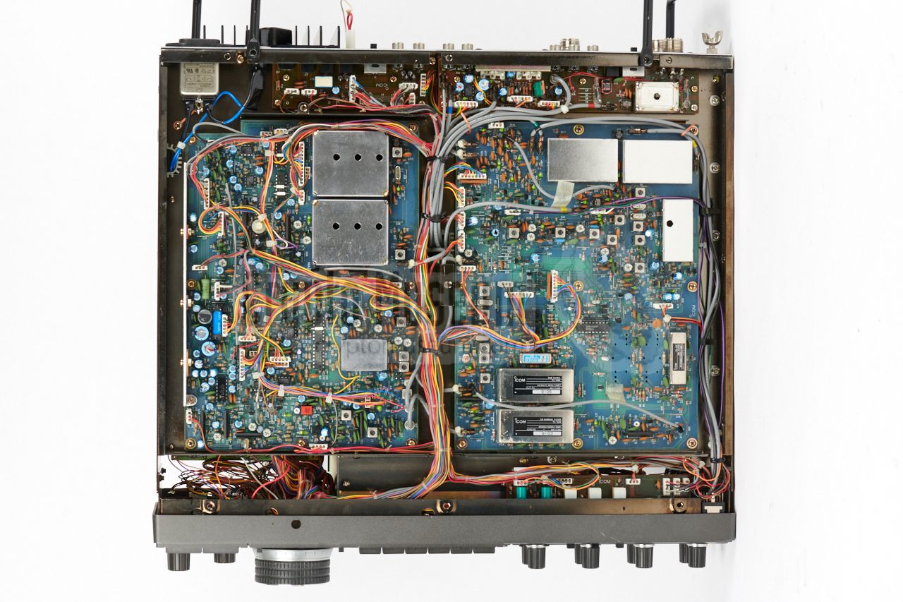
The image on the right shows the conventional transformer of the IC-R9000.
It is fitted in the lower section of the case, at the rear right.
In our case, we decided to leave it intact, as it allows
the unit to be powered from the mains during demonstrations. Note that, when
the receiver is powered from the PAN-2000 FFT unit, the jumper connector
at the rear of the receiver has to be removed, as the socket is needed for the
15V DC power supply from the PAN-2000. Do not lose the jumper plug,
as you might need it when powering the receiver from the mains.
|
|
|
|
Note that the receiver requires a minimum DC voltage of 13.5V for a proper
operation. It will not work well with a lower voltage. In the case of
the PAN-2000 system, it was powered by the 15V DC output of the
FFT Processor. Suitable connectors for the DC INPUT of the IC-R9000 can be
difficult to find, but it is possible to modify an old harddisc power
connector for this purpose.
|
|
The receiver has a timer switch at the top left of the front panel,
just below the power switch. If this switch is pressed accidentally,
the device can not be turned on by supplying power and switching it
ON. As in such cases, the PAN-2000 will be completely dead, it might
be wise to disable the timer switch altogether.
|
|
At the center of the front panel of the IC-R9000 is a monitor, or
display, which is built around an amber cathode ray tube (CRT).
A CRT requires a high voltage and usually consumes a significant amount
of energy. Although it is possible to turn the display OFF by pressing
the DISPLAY button at the front panel, this switch only interrupts
the video signal and not the power supply.
As the display was not needed — the PAN-2000 has its own display —
it was decided to cut the power supply to the monitor, as this would
reduce the total power consumption of the system by 1A.
|
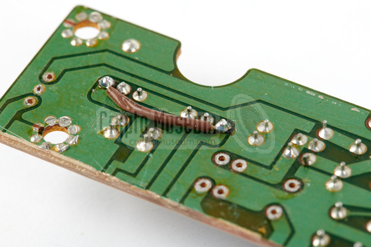
This was done by cutting the brown wire from the connector at the back
of the display casing, and bringing it to the back of the radio,
were it was soldered to the outer pins of the (modified) 5-pin DIN DATA socket.
When for some reason the display was needed, e.g. when servicing the
radio, the display could be enabled by installing a shorting plug in the
former DATA socket.
When the modified Dutch IC-R9000 receivers were decommissioned,
many of the new owners
reverted this modification by soldering the wires back together, in order
to restore the display.
|
|
|
|
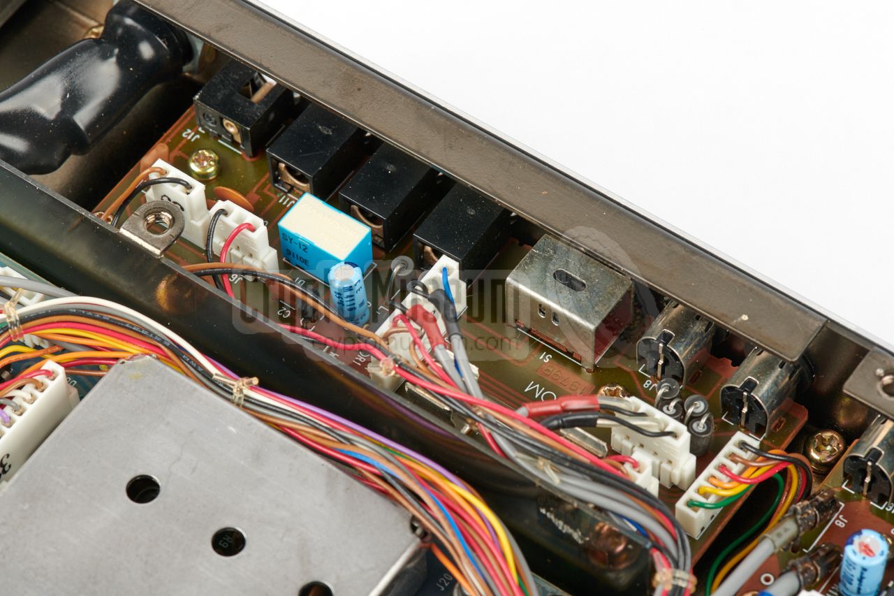
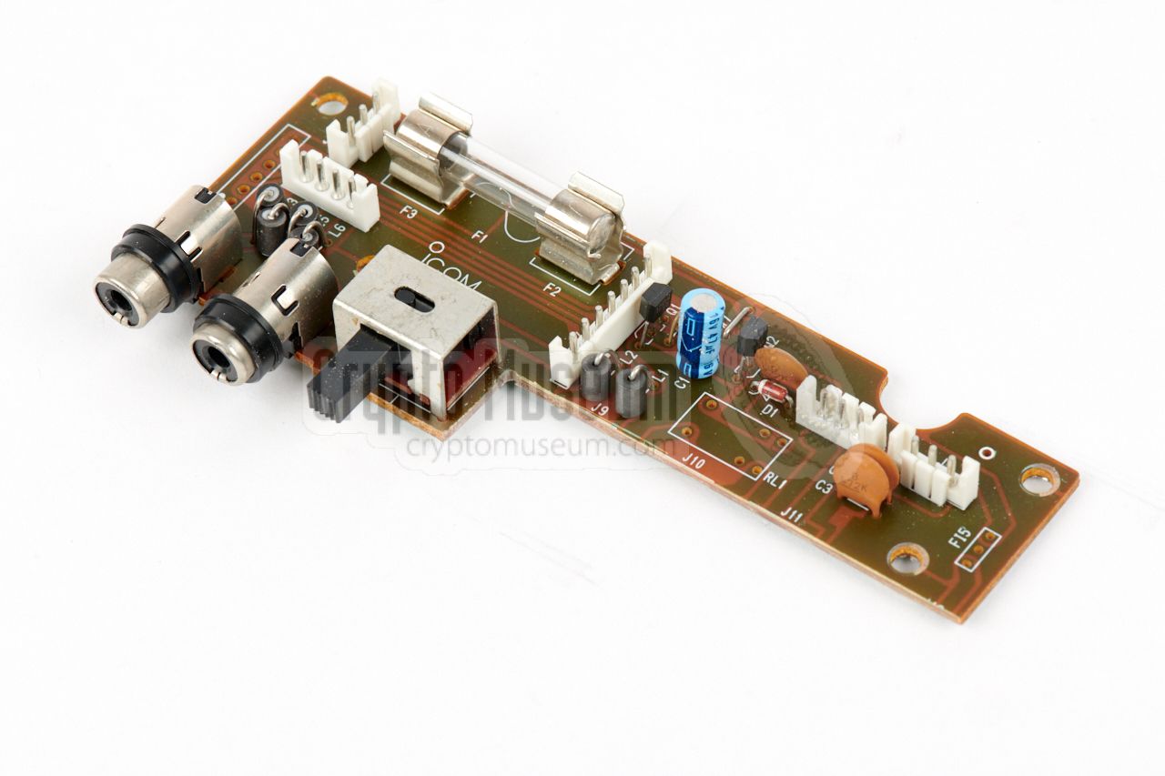
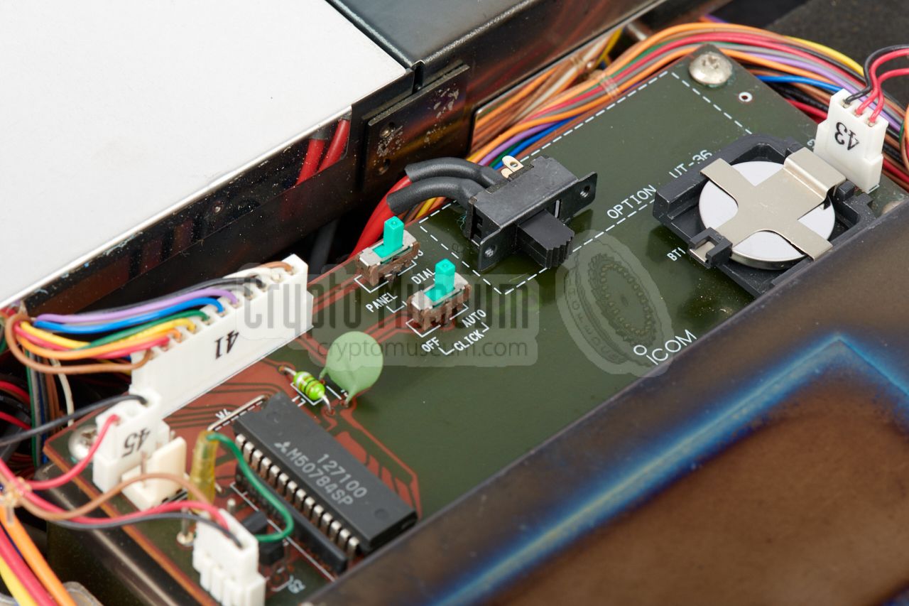
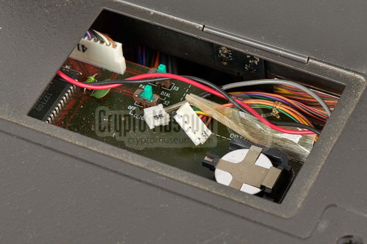
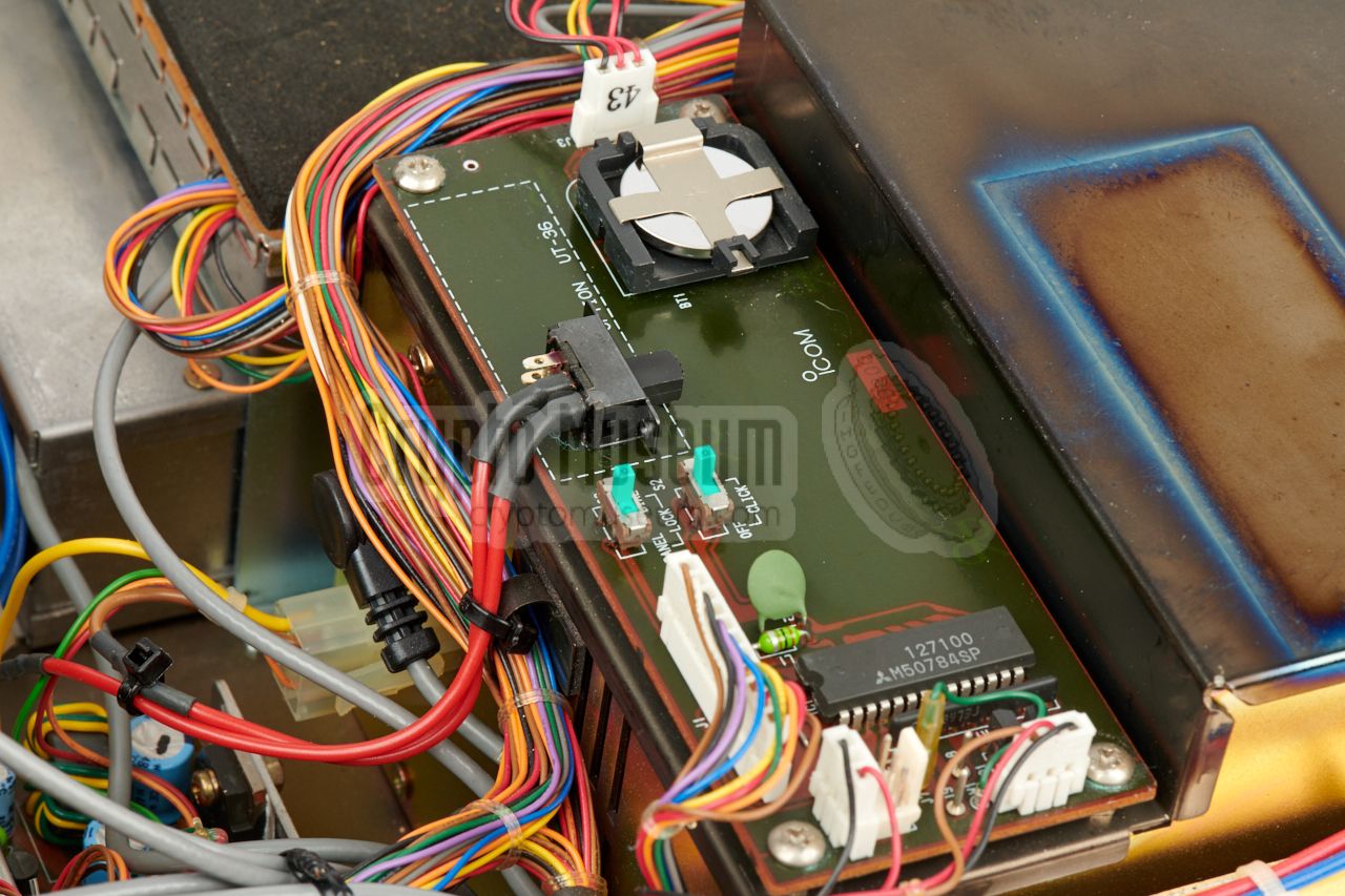
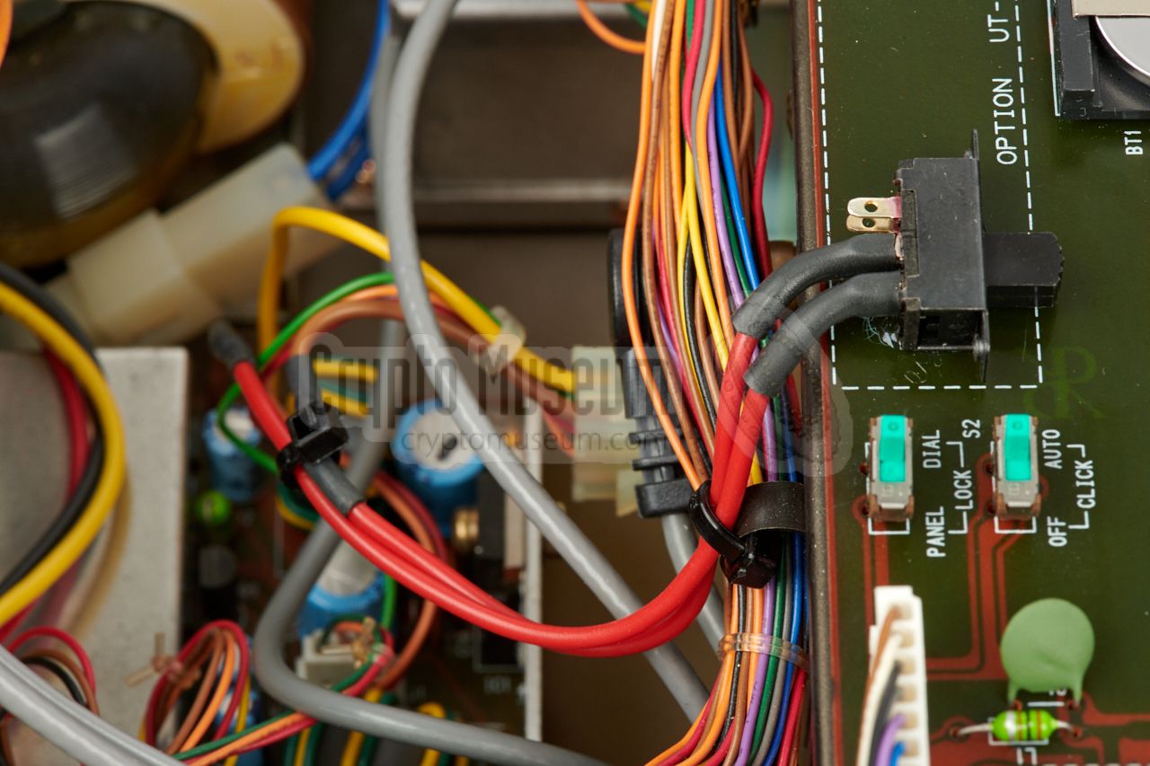
We decided to take a different
approach, by adding a switch to the options board (below the small
removable panel at the top
of the receiver). This allows the monitor to be
enabled/disabled easily for demonstration and testing purposes.
This solution is shown in the image above. For this modification,
only the brown wire from the connector
should be interrupted by the switch.
|
|
|
Discriminator output added
TUNING
|
|
|
|
In order to be able to tune-in more precisely to a station, the IC-R9000
has a discriminator meter (shared with the S-meter). In case of the
PAN-2000 however, the receiver is controlled remotely and the
discriminator signal is not available externally, so it is necessary to add an output for it.
|
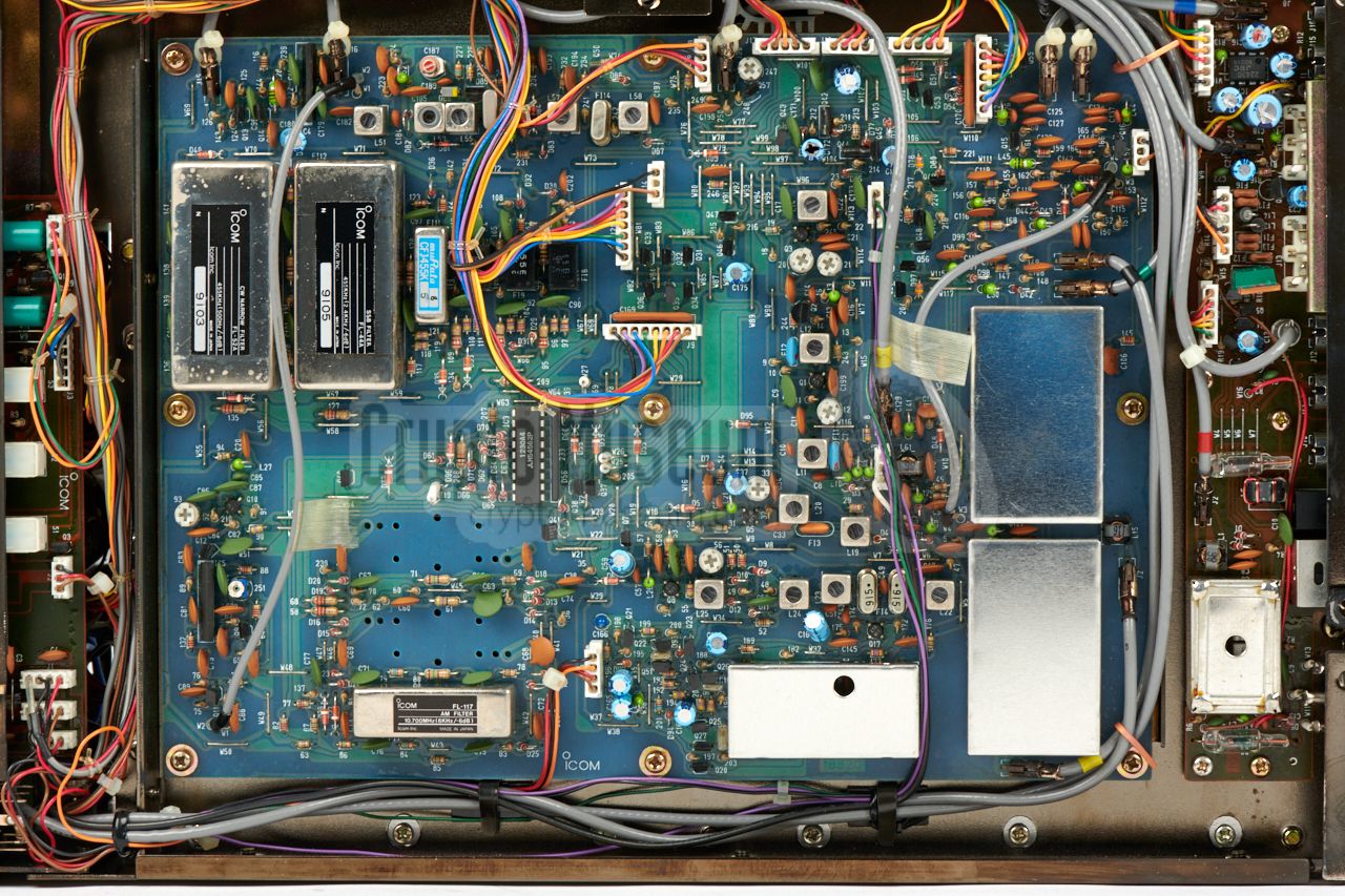
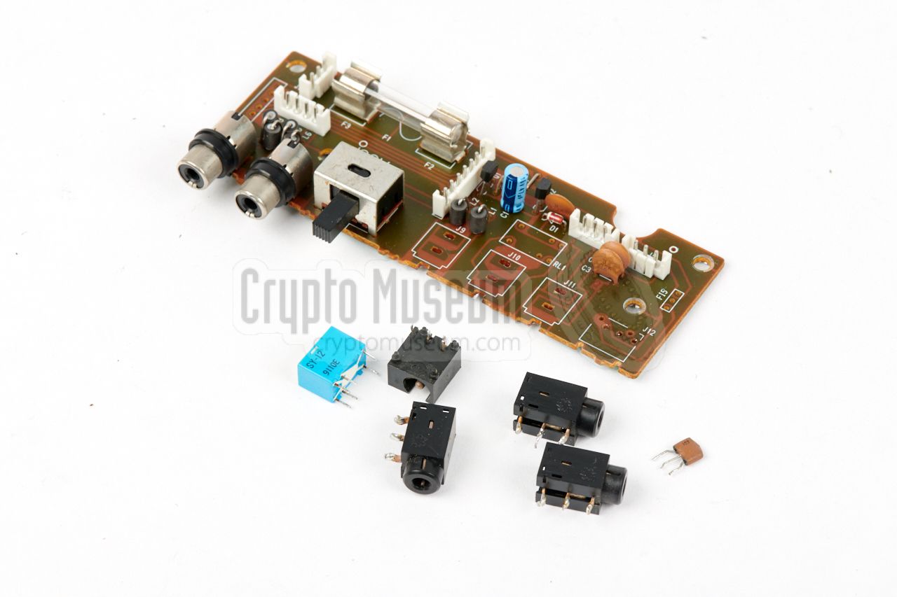
To accomodate a BNC socket for this additional output, the narrow
connection board (at the bottom side of the receiver, near the mains fuse)
will have to be modified (as described above).
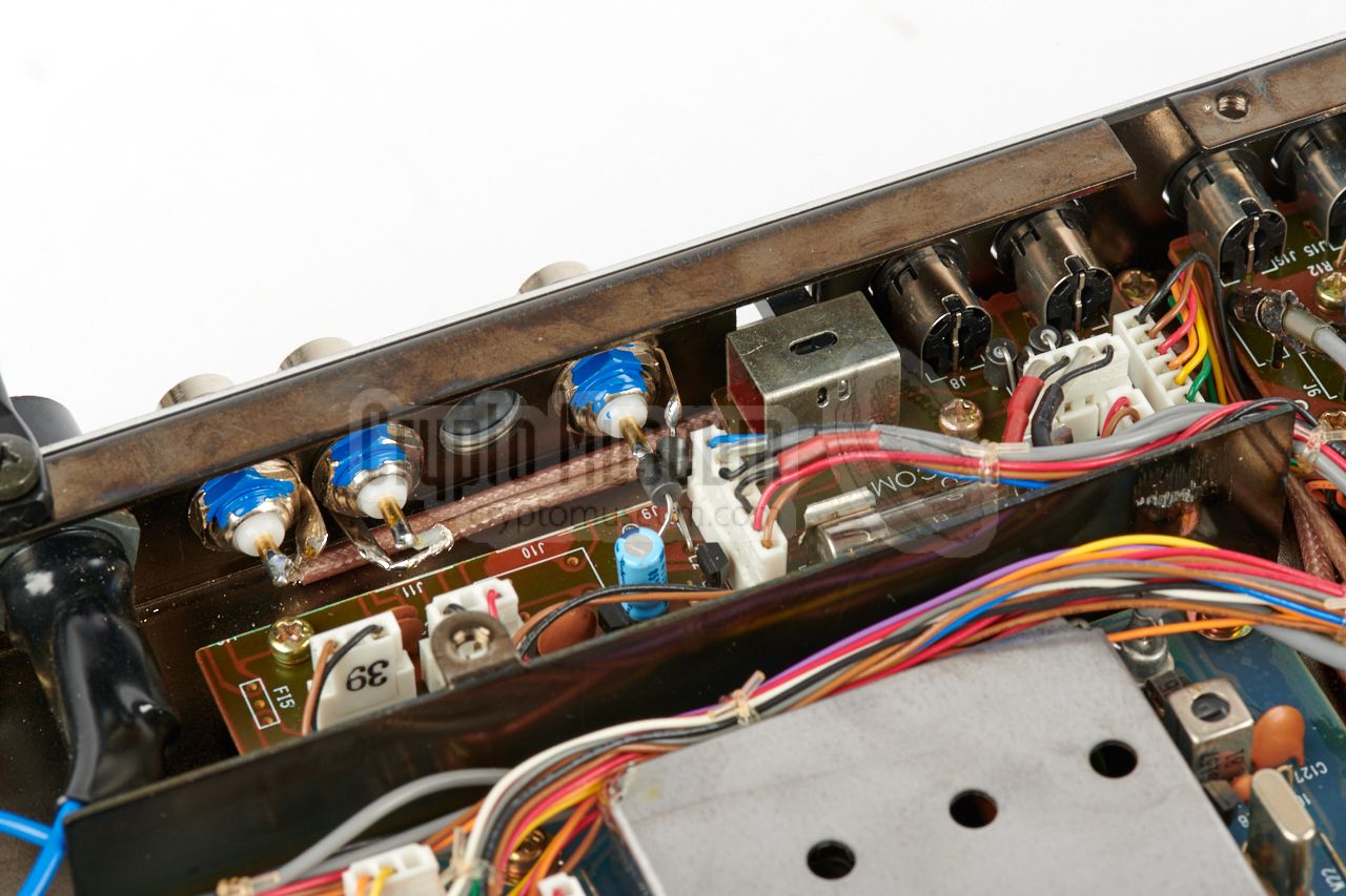
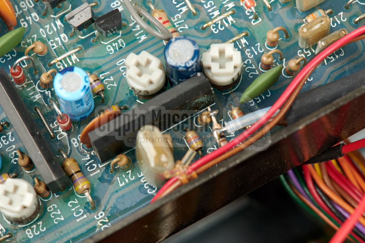
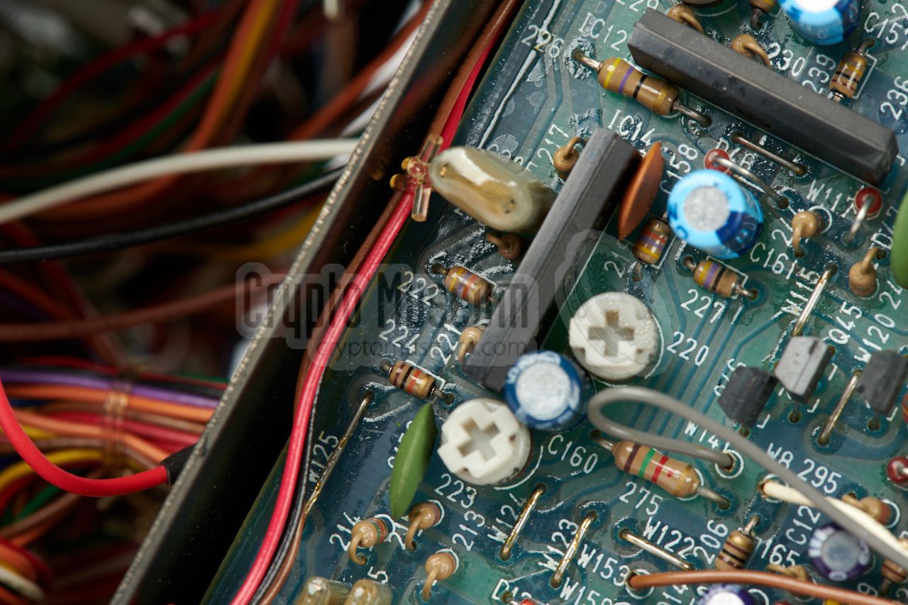
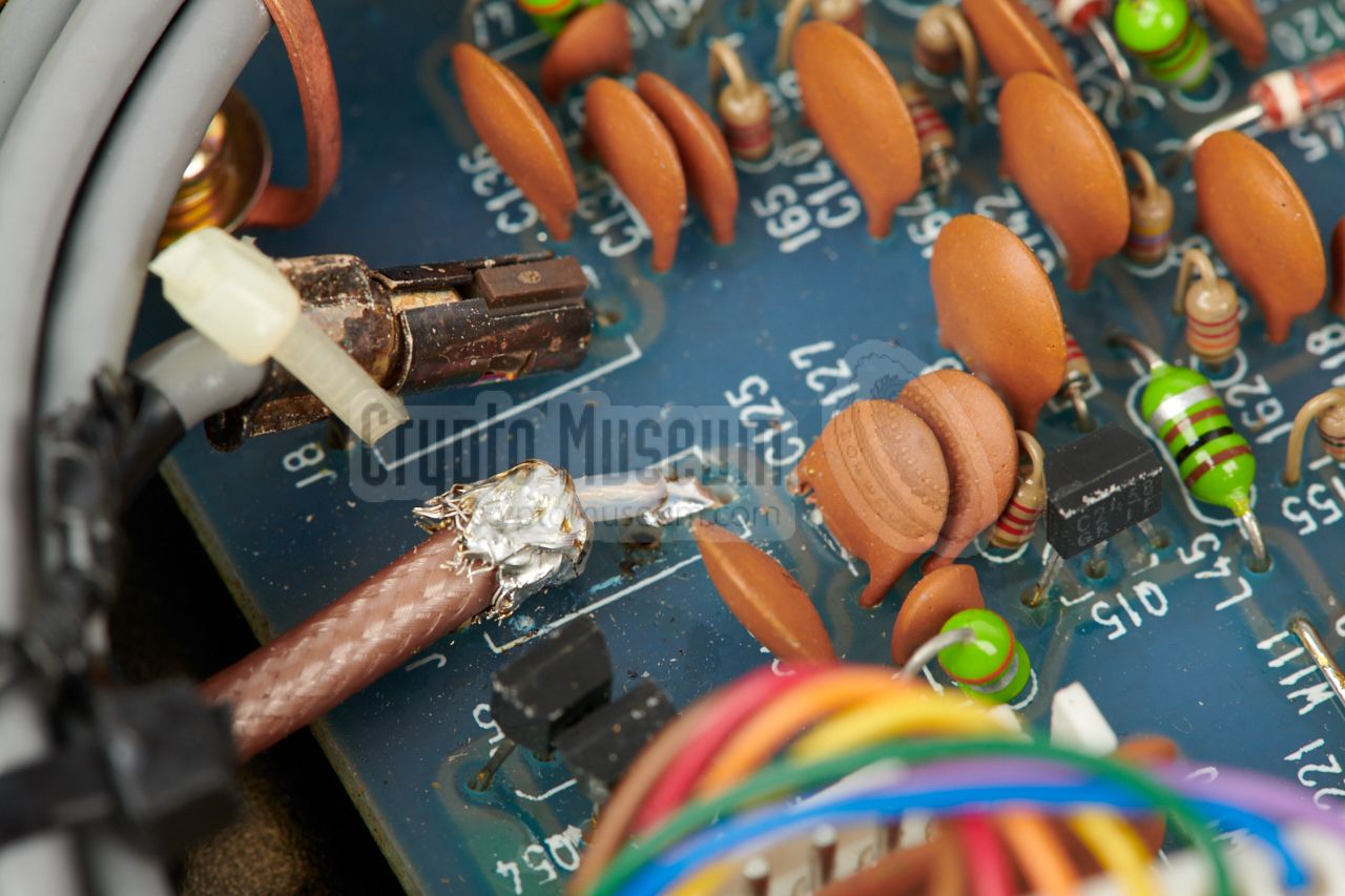
The new discriminiator output is made by taking the discriminator signal
at pin 1 of IC14 on the demodulator board
(also available at the top of R221), and bringing it out via a 10K resistor
that is placed in series with a coaxial cable that leads
to the new BNC socket at the rear.
The shield of the coax is connected to the ground
side of R224 (the pin nearest to the edge of the PCB).
|
|
|
The new (modified) situation is shown in the image above. On the IC-R9000
receivers used by the RCD,
the discriminator output was labelled CM OUTPUT (center meter output). It
should be connected the TUNING socket at the rear of the PAN-2000
FFT Unit, using a BNC-BNC cable.
➤ View circuit diagram and PCB (PDF)
|
|
At the rear of the receiver, a socket is available with the 10.7 MHz
IF output. This signal is needed by the PAN-2000 in order to be able to
create a panorama display. In practice however, there are several problems
with the existing IF output, as a result of which modifications are
necessary.
|
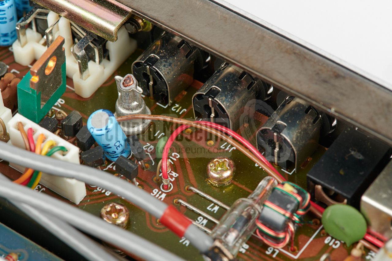
In the default situation, the IF signal is available on a CINCH socket at
the rear, close to the ACC accessory socket. This is
a bad choice, as CINCH sockets are intended for low-frequency signals only.
Furthermore, the place that is chosen for the socket is not a very good one,
as it appears to be picking up spurious signals and noise.
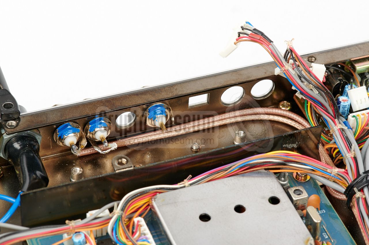
For this reason, a new 10.7 MHz IF output has been created in the vacated space
near the connection board (see above). The IF signal can be made available
on a new BNC socket, or via a fixed cable to the IF input of the PAN-2000.
|
|
|
|
In our case, we decided to add a BNC socket, so that the receiver does
not have any fixed wiring. To accomodate the new socket, the
connection board behind the rear panel has to be modified.
This is described above.
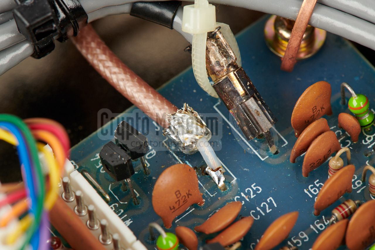
The existing (grey) coaxial cable is
removed (cut-off)
and replaced by a better quality teflon one, that is
soldered directly to the pins of
the removed socket on the IF unit.
|
- AT/RCD technician, Personal correspondence
April 2018 — August 2018.
- Nico van Dongen (PA3ESA), PAN-2000 and system description
Crypto Museum, July 2018.
|
|
|
|
Any links shown in red are currently unavailable.
If you like the information on this website, why not make a donation?
© Crypto Museum. Created: Sunday 26 August 2018. Last changed: Sunday, 02 September 2018 - 21:17 CET.
|
 |

|
|
|


