|
|
|
|
|

|
|
← Yugoslavia Cold War RTP-8 SSB/3 →
Yugoslav spy radio set
RTP8-SSB, commonly abbreviated to RTP-8 was a single-piece
spy radio set,
developed around 1970 in the former Yugoslav Republic
and built by the
Institut za Elektroniku Telekomunikacije i Automatiku
(IETA) 1 in Zagreb (Croatia).
Both receiver and transmitter are crystal driven, and have a frequency span
of 3-7 MHz, divided over two bands. The receiver is suitable for SSB and CW.
|
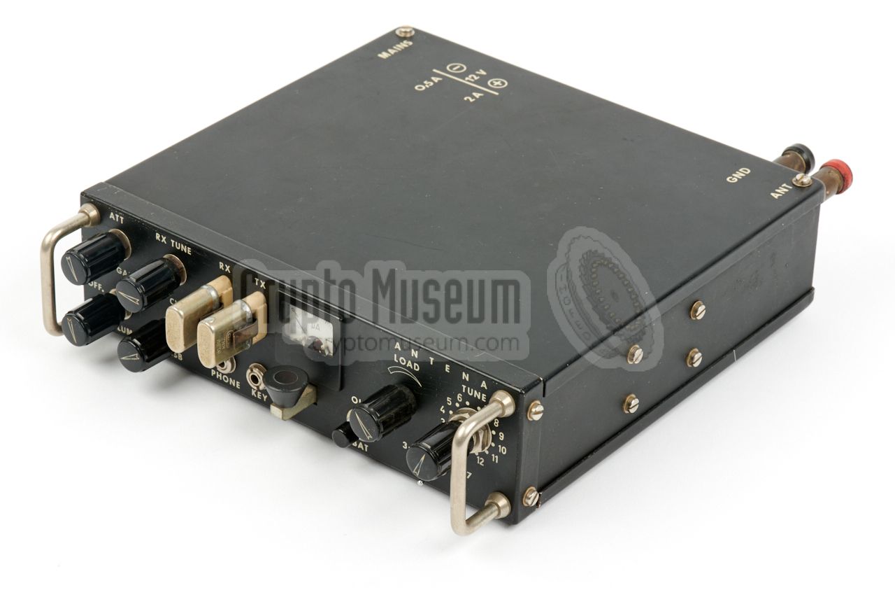
The radio was available as a single-piece all-in-one unit (RTP8-SSB),
and as a three-piece variant (RTP8-SSB/3).
The single-piece variant is shown here.
It consists of a transmitter with an output power of 6-8W,
a receiver with a 1µV sensitivity, and a built-in
power supply unit that is suitable the 110/220V AC mains
and a 12V DC source.
The three-piece version was used for true agent communications and is probably
the rarer one of the two. During the 70s and 80s, it was used for intelligence
gathering inside Yugoslav Republic 2 and for espionage in the neighbouring countries.
|
|
|
The single-piece version measures 23.5 x 21 x 5.5 cm and weighs just 3 kg.
It is predominantly built with parts from the US, Germany and The Netherlands,
made by companies such as Philips,
RCA
and Siemens.
The three-piece version is slightly
heavier and each piece has a different size, but is otherwise identical.
The 3 units are connected together by means of short power cables.
|
|
RTP8-SSB and RTP8-SSB/3
radios are extremely rare as, because of the Yugoslav Wars
(1991-2001) [1], not many of them have survived.
The one shown here, was used by the Croatian intelligence service
in the years before the Yugoslav Wars and has miraculously survived.
It is still in operational condition
and has been used for amateur radio communication until recently.
|
-
Institute for Electronics, Telecommunications and Automation.
This company also built the Collins PRC-515 and many other radios under
licence of the original manufactuers. The company still exists today as
Radio Industry Zegreb (RIZ).
-
The Yugoslav Republic, also known as Yugoslavia,
was a country in Southeastern Europe for most of the 20th century.
Although it was a communist state behind the
Iron Curtain, it was never
part of the Warsaw Pact.
After the Yugoslav Wars (1991-2001), it was dissoluted
and split into six individual republics.
|
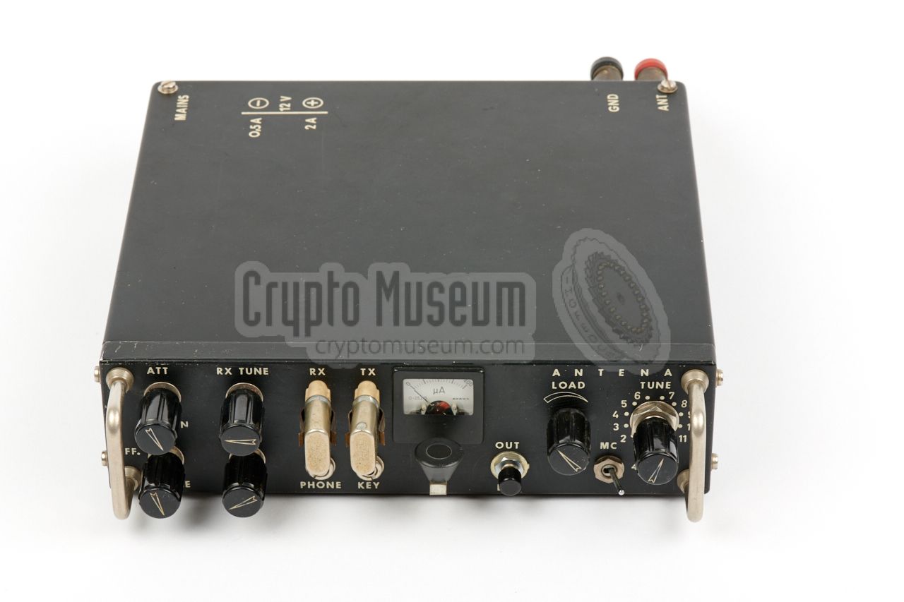
The image below provides an overview of the controls on the
single-piece variant. Both transmit and receive frequency are controlled
by crystals that are plugged into a socket at the front panel. Note
that the receive crystal should by 9 MHz higher than the actual
frequency.
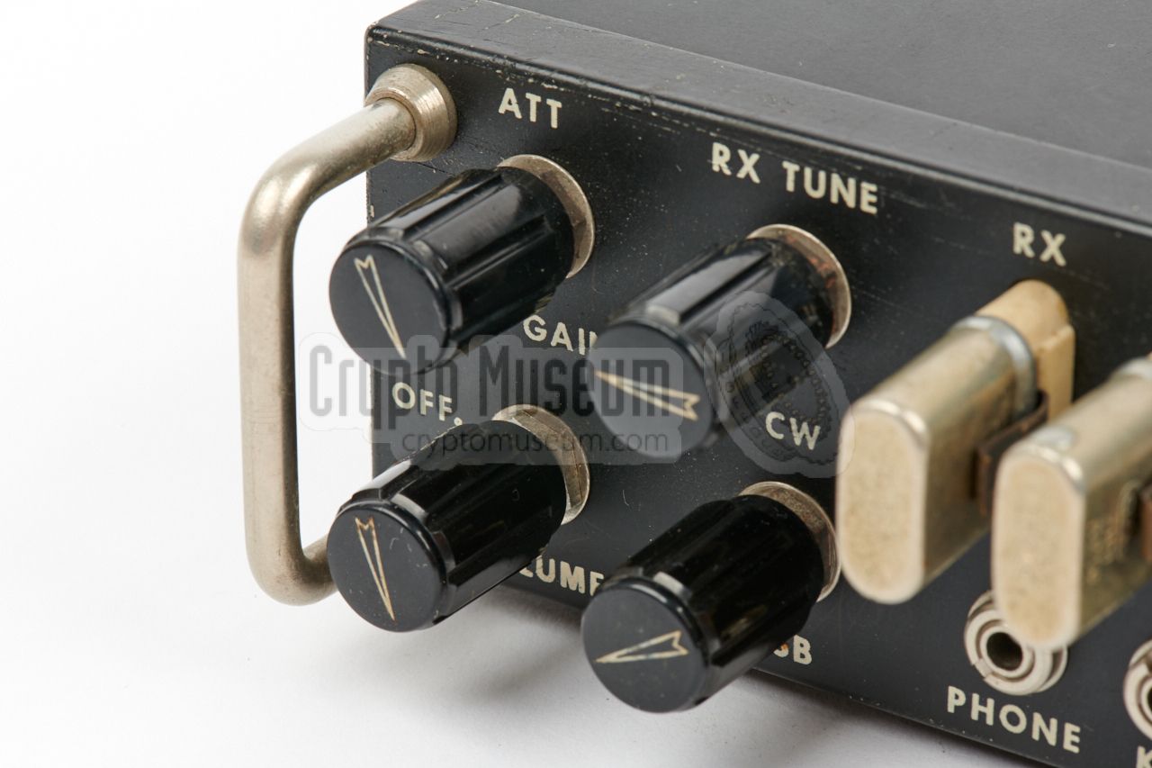
Two knobs on the receiver can be pulled-out to enable Attenuator
and the Beat Frequency Oscillator (BFO). Audio output is available on
a 3.5 mm jack socket to which the stethoscope headphones are connected.
The transmitter has two knobs that are tuned for maximum power output,
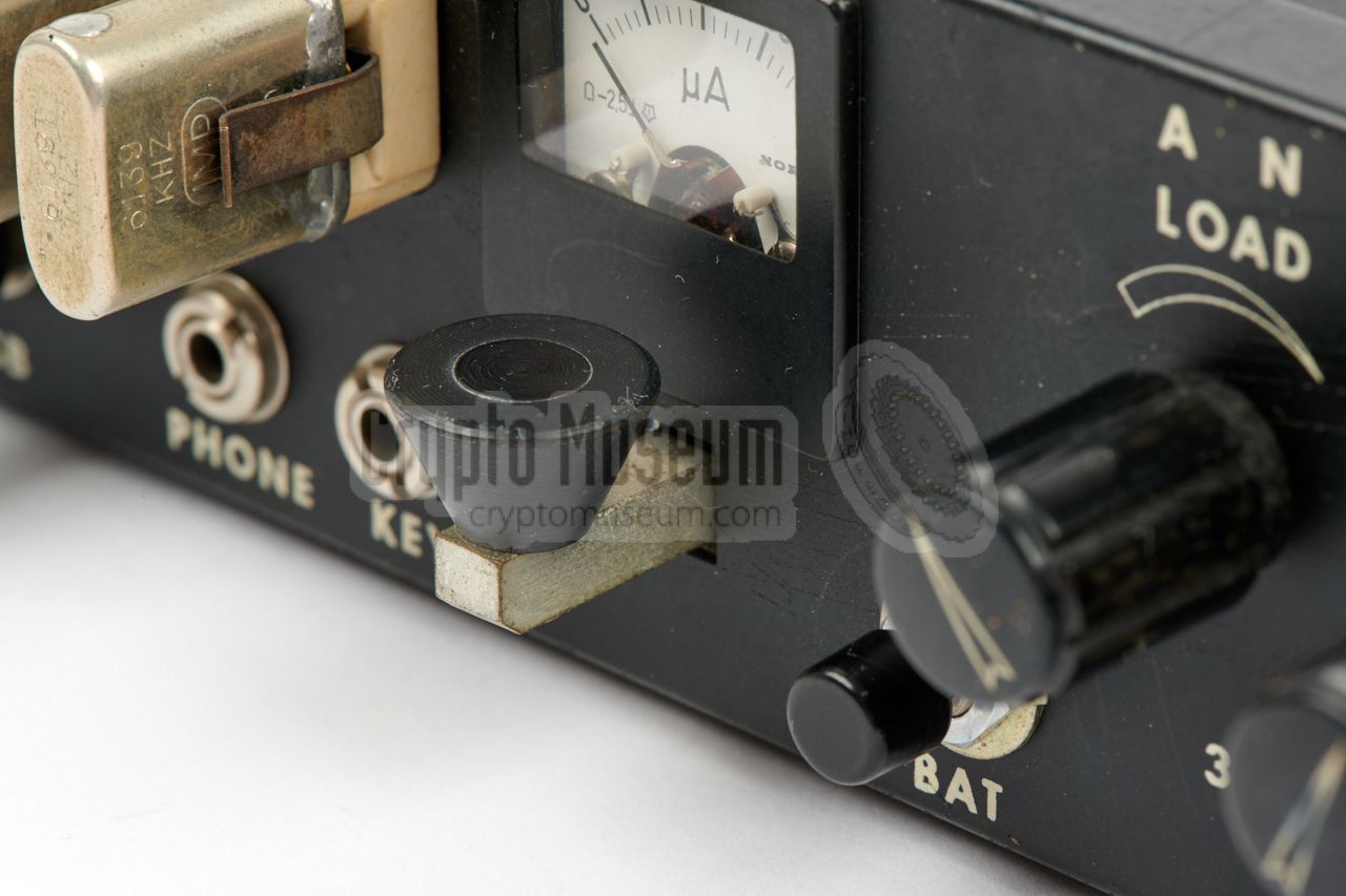
using the meter as a power indicator. An external morse key should be
connected to the 3.5 mm jack socket at the bottom left. Alternatively,
the built-in morse key,
mounted just below the meter, can be used.
The radio is powered by a 12V DC source, either from the 110/220V AC
PSU, or from an external battery. In the latter case, a push-button on
the front panel of the transmitter can be used to check the voltage.
As long as the button is depressed, the meter shows the DC power voltage.
All text on the front panels of the units is in English, which was
quite common for any Cold War spy radio set, regardless its origin.
This was done for two reasons: first of all to fool the local police
in the guest country, making them believe it is a British
or American device, and secondly because the operator was often a
foreign national who did not speak the language of the originating country.
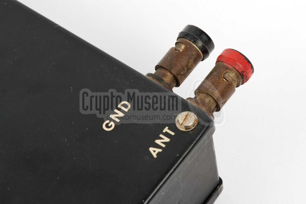
Note the incorrect spelling of the word ANTENNA in the top right corner.
|
- RTP-8 SSB
This is the all-in-one version of the radio set.
The front panel is comprised of the receiver (left) and the transmitter
(right), whilst the PSU is fitted at the rear end of the transmitter.
The internals are identical to the 3-piece version, but the wiring
is somewhat different. The radio set featured here, is of this type.
- RTP-8 SSB/3
This is a three-piece variant of the above radio, consisting of a PSU,
a transmitter and a receiver.
Because of the smaller size of the individial
pieces, it can be hidden more easily. The parts are connected together by
means of short power cables.
➤ More information
|
|
Operation of the RTP8 is pretty straightforward and similar to other spy radio
sets. Unlike most other sets of the era however, the
receiver does not have a VFO and can therefore not be freely tuned over the
frequency bands. Instead it needs a dedicated crystal for the selected channel.
|
The device can be powered directly from the AC mains.
After selecting the appropriate channel, probably from
a predetermined list or schedule, the crystals
for that channel should be inserted into the receiver and transmitter
crystal sockets at the front panel, left of the meter. Note that the
matched TX and RX crystals are not identical.
Suitable headphones should be connected to the PHONE
socket of the receiver.
The receiver may now be turned ON by rotating the VOLUME knob clockwise.
After a short delay, the typical radio noise should be heard through the headphones.
|
|
|
If no noise is heard, turn the RF GAIN knob fully clockwise and turn off
the attenuator (ATT) by pushing-in the RF GAIN knob. Adjust the RX TUNE knob
for maximum noise. This tells us that the RX front-end is optimally
tuned for the selected frequency. The receiver is now ready for use.
After connecting a suitable antenna to the
terminals at the rear,
press the morse key and adjust the TUNE and LOAD adjustments for a maximum
meter reading. The transmitter is now ready for use and messages can be sent
using either the built-in morse key
(just below the meter) or an externally
connected one (recommended). Although no external keys were supplied with
the radio set, operators were encouraged to select the key of their choice
and connect it to the transmitter.
|
|
A complete RTP8 radio station consists the following parts:
|
The RTP-8 shown in the image on the right is fully self-contained.
It has a built-in mains power supply unit, but can also be powered by
an external 12V DC source.
This version of the RTP-8 was typically used in fixed radio stations,
or carried around as an ad-hoc clandestine station, for example built inside
a common inconspicuous briefcase.
|
|
|
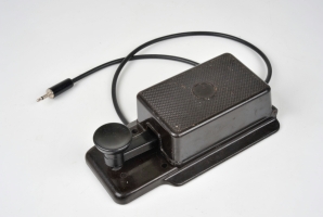
The receiver of the RTP-8 delivers its audio output onto a 3.5 mm jack
socket at the front panel. This is suitable for the connection of a standard
earpiece from a portable radio.
In an operational context, the RTP8 came with the Sennheiser stethoscope-style
headset shown in the image on the right.
|
|
|
In an operational context, the RTP8 was suppied with several pairs of
crystals. Each pair consisted of a crystal for the transmitter (TX) and
another one for the receiver (RX). Note that the frequency of the RX crystal
has to be 9 MHz higher than the actual frequency, in order to match the IF. 1
The crystals were manufactured by Institut Mihailo Pupin (IMP) in Belgrade (Serbia), and were packed in small carton boxes, bundled in pairs (TX/RX)
by means of cellotape.
|
|
|
-
Note that both crystals are marked with the TX frequency, followed
by the letter T (transmit) or R (receive), e.g. 5833T and 5833R. In this
example, the RX crystal is actually for 14833 kHz, whilst the TX
crystal is for 5833 kHz. The RX crystal is always 9 MHz higher than the
TX crystal.
|
The RTP8 was generally used in combination with an external morse key
that was connected to the 3.5 mm mono jack at the front panel of the
radio set.
The choice of key was free, so that the operator could
pick the one with the best hand. Quite often, old German Wehrmacht
WWII keys were used, like the one shown here.
If the operator had forgotten his key, or when the external key was broken,
the small internal key,
below the meter on the front panel of the
transmitter, was used as a temporary solution.
|
|
|
The PSU can be connected to the AC mains (110 or 220V)
via the 3-pin Hirschmann socket at the rear panel.
A suitable cable that fitted the most common wall sockets
in Europe, was supplied with the set, such as the one
shown here.
For use on other networks, a separate cable had to be supplied
or an alternative mains plug had to be fitted to the existing
cable. Alternatively a common travel adapter could be used
as well.
|
|
|
|
Depending on the circumstances, the RTP8-SSB
was powered by the built-in power supply unit or by an
external 12V DV voltage, such as the battery of a car. When used in the
field, battery operation would be recommended, whilst in an urban
environment the internal PSU was used.
|
The PSU allows the radio to be operated from the most common 110V and
220V AC networks. It produces a stabilized 12V DC voltage that
drives both the transmitter and the receiver, switched – together
with the antenna – by an internal relay.
A suitable wire antenna should be connected to the spring-loaded antenna
terminals at the rear.
When the transmitter is off (i.e. morse key up), the receiver is powered
and the wire antenna is connected to the receiver.
As soon as the morse key is pressed, the internal relay passes both power and antenna directly to the transmitter.
|
|
|
The image above shows the power terminals in the rear left corner of the
radio set. The square 3-pin socket at the edge accepts the mains power cable.
The two banana sockets (red and black) are for connection of an external 12V
DC power source. Above these terminals are the fuses.
|
|
The interior of the RTP8-SSB is easily accessible. By removing the top and
bottom panels – each of which is held in place by four 3 mm screws – all
internal parts can be reached, as shown below.
|
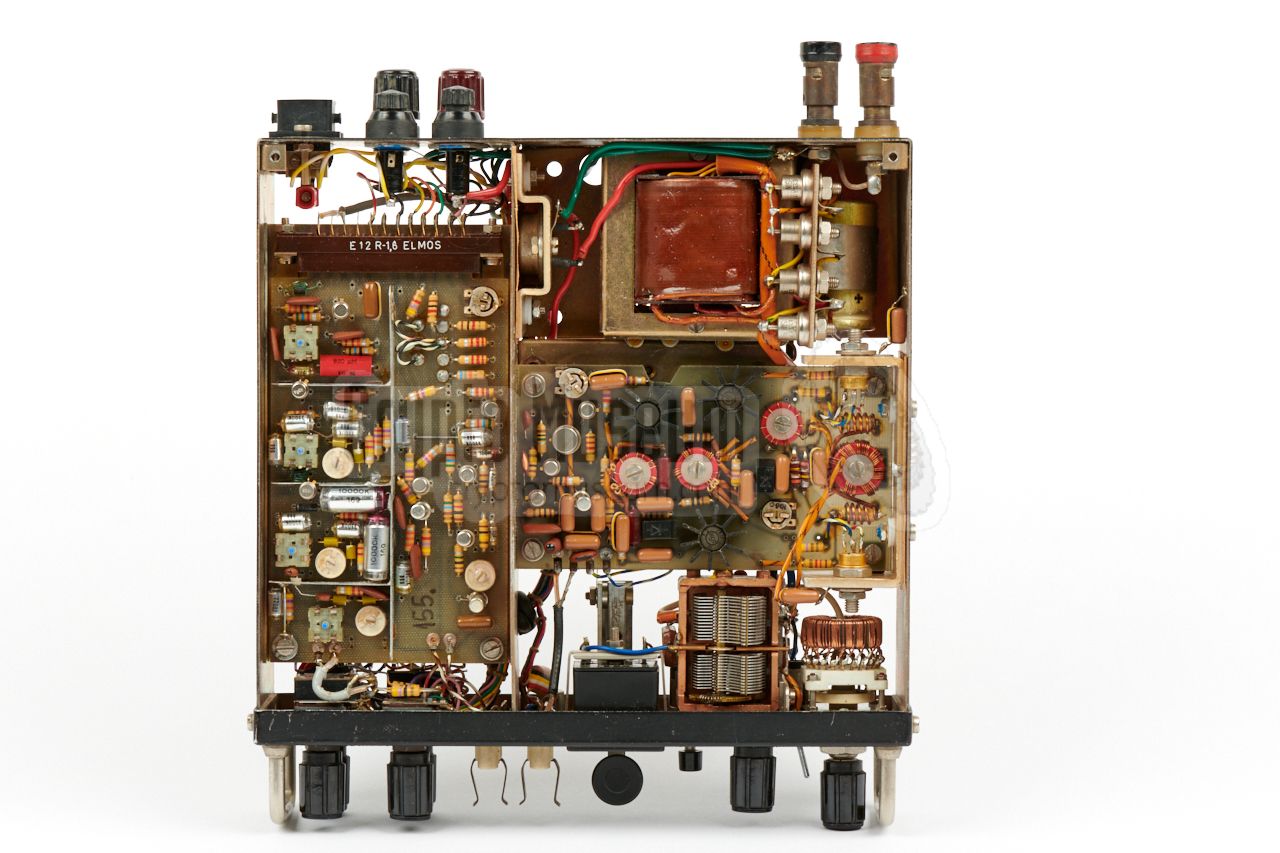
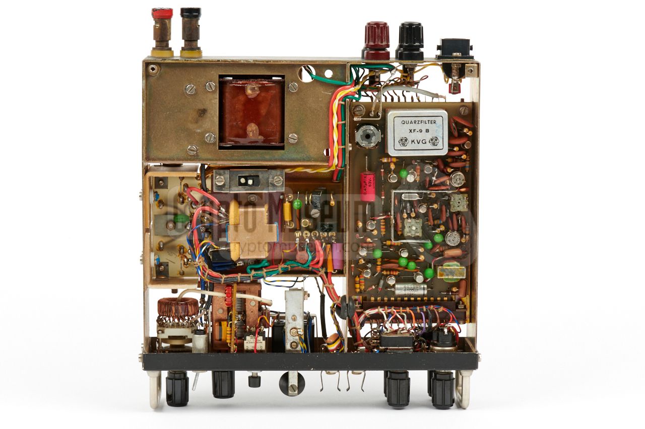
The image on the right shows the interior of the RTP-8, seen from the top,
after both covers have been taken off. At the left is the receiver, whilst the
transmitter is at the front right. The PSU is at the rear right, with the
transformer just visible.
When comparing the RTP-8 shown here, with the three-piece variant,
it becomes obvious that they are nearly identical. In fact, it
is merely a metal frame with 3 individual units: the transmitter,
the receiver and the power supply unit. The only difference
is that in the single-piece version, the three units are connected by
the internal wiring.
|
|
|
|
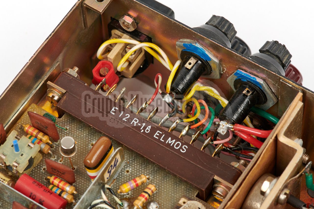
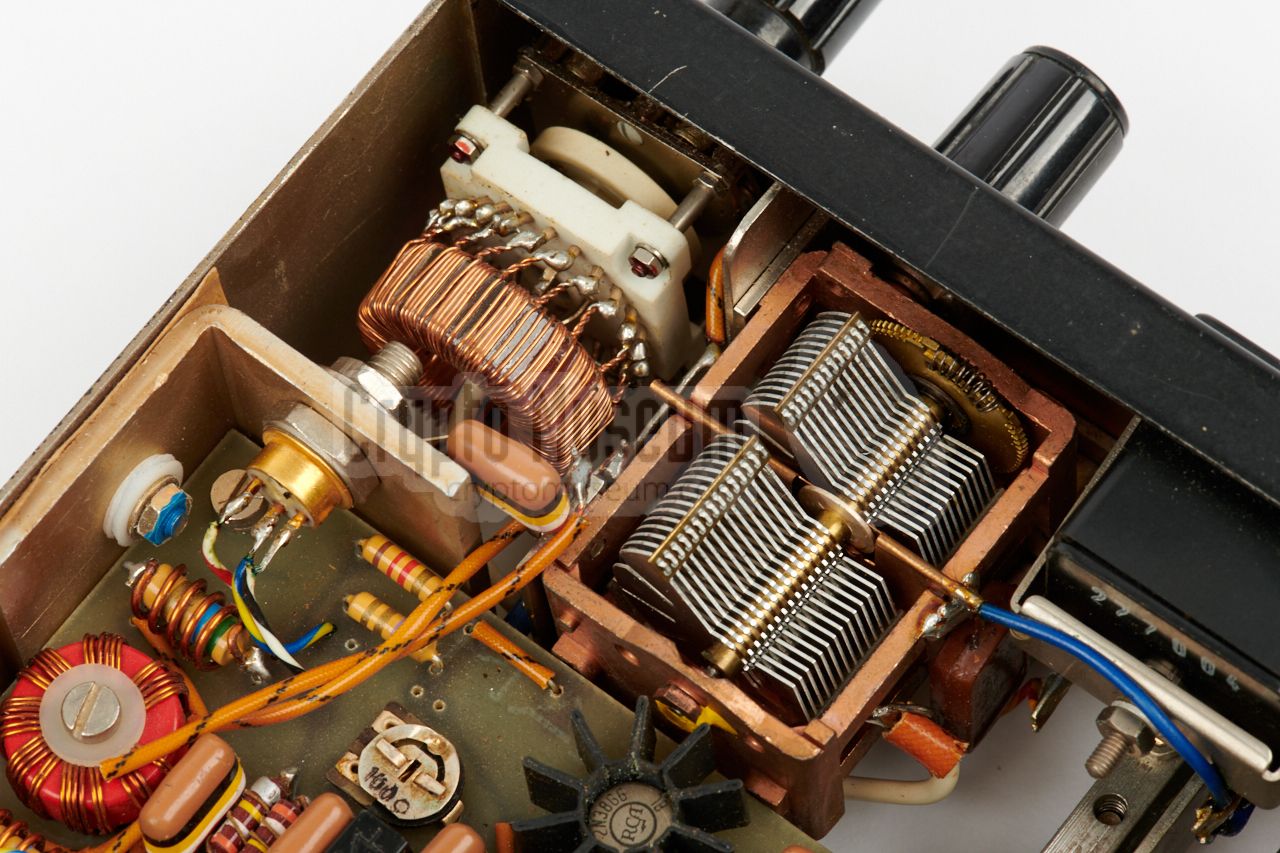
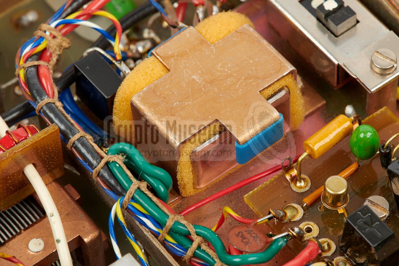
The radio's metal frame is roughly divided into three sections, that are
separated by metal panels. The leftmost compartment holds the
receiver, which
consists of two PCB's
mounted back-to-back, each slotted into a card-edge
socket. The transmitter is located at the front right and consist of a
single sided PCB,
with the RX/TX relay mounted below it.
The parts of the antenna tuner,
are fitted between the transmitter board and the front panel.
Further images below.
|
Input 110V or 220V AC (switch selectable) Output 12V DC Current 2A max
|
Frequency 3 - 7 MHz (crystal operated) Mode SSB, CW (morse) Sensitivity 1µV Audio 10 mW Current 40 mA
|
Range 1 3-4 MHz (80 m) Range 2 4-7 MHz (40 m) Output power 6 to 8 Watt Mode CW (morse)
|
|
|
|
Any links shown in red are currently unavailable.
If you like the information on this website, why not make a donation?
© Crypto Museum. Created: Tuesday 29 March 2016. Last changed: Wednesday, 05 November 2025 - 12:11 CET.
|
 |

|
|
|