|
|
|
|
|

|
|
← Yugoslavia Cold War RTP-8 SSB →
Yugoslav spy radio set
RTP8-SSB/3, commonly abbreviated to RTP-8/3 was a 3-piece
spy radio set,
developed around 1970 in the former
Yugoslav Republic, and built by the
Institut za Elektroniku Telekomunikacije i Automatiku
(IETA) 1 in Zagreb (Croatia).
Both receiver and transmitter are crystal driven, and have a frequency span
of 3-7 MHz, divided over two bands. The receiver is suitable for SSB and CW.
|
The set was available as a single-piece
all-in-one unit (RTP8-SSB)
and as a three-piece
unit (RTP8-SSB/3). The latter is shown on the right.
It consists of a transmitter (TX) with an output power of 6 - 8W,
a receiver (RX) with an input sensitivity of 1µV, and a power supply unit
(PSU) that was suitable for 12V DC and 110/220V AC.
The three-piece version was used for true agent communications and is probably
the rarer one of the two. During the 70s and 80s, it was used for intelligence
gathering inside Yugoslav Republic 2 and for espionage in the neighbouring countries.
|
|
|
The single-piece version measures 23.5 x 21 x 5.5 cm and weighs just 3 kg.
It is predominantly built with parts from the US, Germany and The Netherlands,
made by companies such as Philips,
RCA
and Siemens.
The three-piece version is slightly
heavier and each piece has a different size, but is otherwise identical.
The 3 units are connected together by means of short power cables.
RTP8-SSB
and RTP8-SSB/3 radios are extremely rare as, because of the Yugoslav Wars
(1991-2001) [1], not many of them have survived.
The one shown here, was used by the Croatian intelligence service
in the years before the Yugoslav Wars and has miraculously survived.
It is still in operational condition
and has been used for amateur radio communication until recently.
|
 |
-
Institute for Electronics, Telecommunications and Automation.
This company also built the Collins PRC-515 and many other radios under
licence of the original manufactuers. The company still exists today as
Radio Industry Zegreb (RIZ).
-
The Yugoslav Republic, also known as Yugoslavia,
was a country in Southeastern Europe for most of the 20th century.
Although it was a communist state behind the
Iron Curtain, it was never
part of the Warsaw Pact.
After the Yugoslav Wars (1991-2001), it was dissoluted
and split into six individual republics.
|
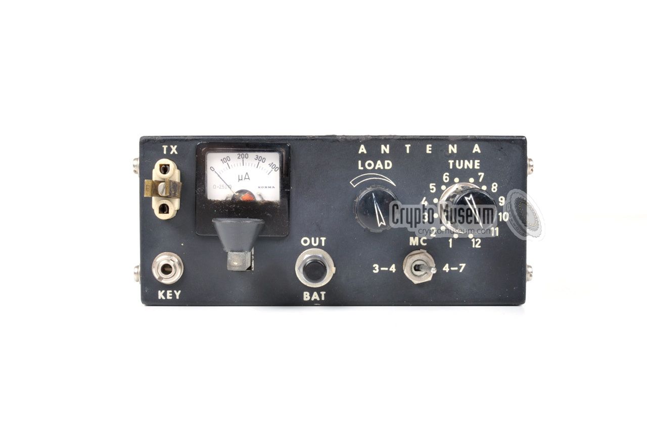
The image below provides a quick overview of the controls on the
3-piece variant. Both transmit and receive frequency are controlled
by crystals that are plugged into a socket at the front panel. Note
that the receive crystal should by 9 MHz higher than the actual
frequency.
Two knobs on the receiver can be pulled-out to enable Attenuator
and the Beat Frequency Oscillator (BFO). Audio output is available on
a 3.5 mm jack socket to which the stethoscope headphones are connected.
The transmitter has two knobs that are tuned for maximum power output,
using the meter as a power indicator. An external morse key should be
connected to the 3.5 mm jack socket at the bottom left. Alternatively,
the built-in morse key,
mounted just below the meter, can be used.
The radio is powered by a 12V DC source, either from the 110/220V AC
PSU, or from an external battery. In the latter case, a push-button on
the front panel of the transmitter can be used to check the voltage.
As long as the button is depressed, the meter shows the DC power voltage.
All text on the front panels of the units is in English, which was
quite common for any Cold War spy radio set, regardless its origin.
This was done for two reasons: first of all to fool the local police
in the guest country, making them believe it is a British
or American device, and secondly because the operator was often a
foreign national who did not speak the language of the originating country.
Note the incorrect spelling of ANTENNA on the front panel of the transmitter.
|
- RTP-8 SSB
This is the all-in-one version of the radio set.
The front panel is comprised of the receiver (left) and the transmitter
(right), whilst the PSU is fitted to the rear of the transmitter.
It is nearly identical to the 3-piece version, but the wiring
is internal.
➤ More information
- RTP-8 SSB/3
This is a three-piece variant of the above radio, consisting of a seperate
PSU,
transmitter
and receiver.
Because of the smaller size of the individial
pieces, it can be hidden more easily. The parts are connected together by
means of short power/antenna cables.
The radio set featured here, is of this type.
|
|
Operation of the RTP8 is pretty straightforward and similar to other spy radio
sets. Unlike most other sets of the era however, the
receiver does not have a VFO and can therefore not be freely tuned over the
frequency bands. Instead it needs a dedicated crystal for the selected channel.
|
The receiver and transmitter should be wired to the PSU
and the PSU should be wired to the AC mains.
After selecting the appropriate channel, probably from
a predetermined list or schedule, the crystals
for that channel should be
inserted into the receiver and the transmitter. Note that the
matched TX and RX crystals are not identical.
Suitable headphones should be connected to the PHONE
socket of the receiver.
The receiver may now be turned ON by rotating the VOLUME knob clockwise.
After a short delay, the typical radio noise should be heard through the headphones.
|
|
|
If no noise is heard, turn the RF GAIN knob fully clockwise and turn off
the attenuator (ATT) by pushing-in the RF GAIN knob. Adjust the RX TUNE knob
for maximum noise. This tells us that the RX front-end is optimally
tuned for the selected frequency. The receiver is now ready for use.
Connect a suitable antenna and counterpoise directly to the terminals of
the receiver or, if the receiver is powered via the transmitter, to the
transmitter. In the former case, the transmitter needs its own set of
antenna wires. Install a suitable crystal at the front of the transmitter.
When an suitable antenna is connected to the transmitter,
press the morse key and adjust the TUNE and LOAD adjustments for a maximum
meter reading. The transmitter is now ready for use and messages can be sent
using either the built-in morse key (just below the meter) or an externally
connected one (recommended). Although no external keys were supplied with
the radio set, operators were encouraged to select the key of their choice
and connect it to the transmitter.
|
|
A complete RTP8 radio station consists of the RTP8-SSB transceiver or, in
case of the three-piece variant, of a transmitter, a receiver and a power
supply unit (PSU),
plus a number of accessories. Below is an overview of the parts that were
usually supplied with the three-piece RTP8-SSB/3.
|
The Power Supply Unit (PSU) measures 16 x 6.5 x 5.5 cm
and is powered either by the 110V or 220V AC mains.
The correct voltage has to be selected with a
slide switch
at the bottom.
The PSU provides a secondary DC voltage between 12 and 13.5V,
to power both the transmitter and the receiver. At the back are
two identical DC outlets. The transmitter and receiver can be powered
individually (by using both sockets), but the receiver can also be
powered via the transmitter.
|
|
|
The receiver measures 23.5 x 8.5 x 5.5 cm
and is powered either directly from the PSU or via the transmitter.
In the latter case, a relay inside the transmitter controls the
power to the receiver and also supplies it with a signal from the
TX antenna. In practice it was commonly powered separately.
The receiver is crystal driven, which means that a
suitable crystal
has to be inserted into the socket at the front right. The frequency
of the crystal has to be exactly 9 MHz higher than the desired receive
frequency.
|
|
|
The transmitter measures 18 x 12.5 x 5.5 cm
and provides an output power between 5 and 8 Watt.
Like the receiver it is crystal-driven, which means that a
suitable crystal
has to be present in the cystal socket at the front left.
Ensure that the band selector (3-4 and 4-7) is in the correct position
for the selected frequency.
After connecting a suitable antenna and inserting a crystal for the
desired frequency, the transmitter has to be matched to the antenna.
This is done by keeping the morse key
depressed and using the TUNE selector
in combination with the LOAD adjustement, to adjust the meter for a maximum
reading.
|
|
|
The receiver of the RTP-8 delivers its audio output onto a 3.5 mm jack
socket at the front panel. This is suitable for the connection of a standard
earpiece from a portable radio.
In an operational context, the RTP8 came with the Sennheiser stethoscope-style
headset shown in the image on the right.
|
|
|
In an operational context, the RTP8 was suppied with several pairs of
crystals. Each pair consisted of a crystal for the transmitter (TX) and
another one for the receiver (RX). Note that the frequency of the RX crystal
has to be 9 MHz higher than the actual frequency, in order to match the IF. 1
The crystals were manufactured by Institut Mihailo Pupin (IMP) in Belgrade (Serbia), and were packed in small carton boxes, bundled in pairs (TX/RX)
by means of cellotape.
|
|
|
-
Note that both crystals are marked with the TX frequency, followed
by the letter T (transmit) or R (receive), e.g. 5833T and 5833R. In this
example, the RX crystal is actually for 14833 kHz, whilst the TX
crystal is for 5833 kHz. The RX crystal is always 9 MHz higher than the
TX crystal.
|
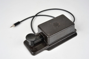
The RTP8 was generally used in combination with an external morse key
that was connected to the 3.5 mm mono jack at the front panel of the
transmitter.
The choice of key was free, so that the operator could
pick the one with the best hand. Quite often, old German Wehrmacht
WWII keys were used, like the one shown here.
If the operator had forgotten his key, or when the external key was broken,
the small internal key,
below the meter on the front panel of the
transmitter, was used as a temporary solution.
|
|
|
Two short (low voltage) power cables are supplied with the three-piece
version of the set. They allow the transmitter and receiver to be connected
to the power supply unit. In addition, the receiver can be powered via
the transmitter.
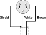
The two cables are wired identically and each have 3 wires: two for the
12V DC voltage (plus and minus) and one for the connecting the TX antenna
to the receiver. The wiring of the cables is given below.
The RTP8-SSB all-in-one version was wired internally.
|
|
|
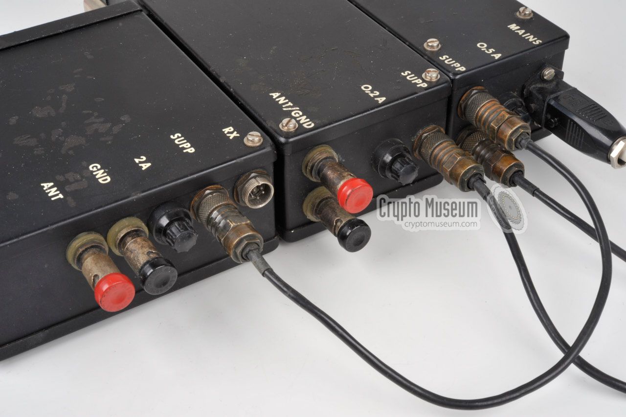
The PSU can be connected to the AC mains (110 or 220V)
via the 3-pin Hirschmann socket at the rear panel.
A suitable cable that fitted the most common wall sockets
in Europe, was supplied with the set, such as the one
shown here.
For use on other networks, a separate cable had to be supplied
or an alternative mains plug had to be fitted to the existing
cable. Alternatively a common travel adapter could be used
as well.
|
|
|
|
Depending on the circumstances, the RTP8-SSB
could be powered by the (internal) power supply unit (PSU) or by an
external 12V DV voltage, such as the battery of a car. When used in the
field, battery operation would be recommended, whilst in an urban
environment the PSU was used.
|
The PSU allows the radio to be operated from the most common 110V and
220V AC networks. It produces a stabilized 12V DC voltage that
drives both the transmitter and the receiver by wiring it up as
shown in the image on the right by means of the two (identical)
short 5-pin power cables.
Note that the PSU has two power outlets that are wired identically,
but that we are using only one of them to connect the PSU to the transmitter's
SUPP socket. The receiver's power socket is then connected to the transmitter's
RX socket. This is done to let the receiver share the TX antenna.
|
|
|
When the set is wired up this way, only the TX antenna has to be connected.
An relay inside the transmitter, switches both power and antenna.
When the transmitter is off (i.e. morse key up), the receiver is powered
and the TX antenna is connected to the receiver via the 3-wire power cable.
Using the morse key, turns the receiver off and connects the
antenna directly to the transmitter.
|
The image on the right shows the internal wiring of the two power sockets
at the rear panel of the transmitter. Two two sockets, here shown at the
top left, are clearly wired differently with a black coaxial cable connected
to the one closest to the edge. It should be connected to the
receiver.
It is also possible to use separate transmit and receive antennas.
In that case, the power socket of the receiver should not be connected
to the RX socket of the transmitter, but to the spare outlet on the PSU.
The receiver is then powered permanently and requires a separate antenna.
|
|
|
This setup can be useful for full duplex traffic, or for split-frequency
operation. The receiver can then be used to monitor a common calling
frequency, whilst transmitting on a dedicated channel.
|
Another advantage of powering the receiver permanently, is that you can
hear your own morse code when sending a message (sidetone).
This is why it is the preferred configuration.
The image on the right shows the RTP8-SSB/3 in the preferred power setup.
Note that both the receiver and the transmitter are directly wired to the
PSU. In this case, transmitter and receiver each need their own antenna
and counterpoise, and the receive antenna must have some distance from
the transmit antenna to avoid damage to the receiver's front-end circuitry.
|
|
|
The three-piece version can also be powered directly from a 12V DC source,
such as the battery of a car. In that case, a different set of cables is
needed (not shown here).
|
|
All parts of the RTP8-SSB are easily accessible. Although we are showing
the three-piece version of the radio here (RTP8-SSB/3), the circuitry
inside the single-piece version is identical. The only differences are
the connectors to the outside world and the internal wiring between the
circuits.
|
|
The receiver is neatly built and has circuits at both sides,
each consisting of a single PCB that is slotted into a card-edge
socket. The image below shows the top section
that contains
the RF stages and the crystal oscillator.
Note that first-grade
components have been used in the design.
|
The design has been kept simple by omitting a Variable Frequency
Oscillator (VFO). As a result, the receiver can not be tuned freely
over the entire frequency range, but needs a crystal to be inserted
into the socket at the front panel. Note that the crystal frequency
has to be 9 MHz higher than the desired actual RX frequency.
The image on the right clearly shows the high build quality of the
unit, with an epoxy PCB and first-class components from West-European
and American manufacturers, such as Siemens, RCA and Philips.
Note the use of styroflex capacitors.
|
|
|
The crystal oscillator
is visible at the front left. It is wired
to the crystal socket on the front panel. Note the use of
a typical type of tunable ferrite coils
or transformers as part
of the tuned circuits of the receiver. The ferrites, with a blue
plastic tip, are most likely manufactured by Siemens.
|
At the bottom
are the IF stage, the crystal filter, the BFO
the detector and the audio section,
with CA3018 and CA3020 ICs from RCA.
The quarz filter
is made by KVG in Germany [2] and has
a centre frequency of 9 MHz.
The receiver delivers its audio output to a pair of
Sennheiser headphones
that is connected at the front panel.
At the rear is the power socket and two press-terminals for
the antenna and counterpoise. The power socket should be wired either to
the PSU or to the transmitter. In the latter case, the antenna signal is
supplied by the transmitter.
|
|
|
In the former case however, the receiver needs its own antenna and
counterpoise. According to the manual [A], a wire antenna of approx. 8
metres should be suitable. It is connected to the red terminal. A suitable
counterpoise (i.e. ground or earth) should be connected to the black terminal.
A wire length of 8 metres is recommended for the counterpoise as well.
|
|
The transmitter is shorter than the receiver, but roughly twice
as wide. The interior can be accessed by removing both the top and
the bottom panels. Inside the transmitter is a metal sub frame that
holds the PCB, the relay and a power circuit.
The rest is mounted to the font panel.
|
The image on the right shows the
top section
that holds the actual
transmitter on a single epoxy PCB. It is neatly built with most
capacitors made by Philips and transistors from a variety of brands.
Also note the four high-quality
toriod transformers
that are bolted to the PCB, and the two
power transistors
mounted to a sub frame.
The antenna matching circuit
is mounted directly to the front panel
and consists of a multi-tap toroid coil mounted to a 12-position rotary
switch, and a variable capacitor for fine tuning, using the small meter
at the left as an indicator.
|
|
|
The meter can also be used to check the voltage of the power source,
with is particularly useful when driving the transmitter from a battery.
As long as the push-button on the front panel is pressed, the meter
shows the battery voltage.
Mounted below the meter is the
internal morse key.
|
The image on the right shows the
bottom section
of the transmitter,
with the internal morse key clearly visible in the corner at the top.
It is wired in parallel to the socket for the external key at the
front panel.
A large electric relay
is visible in the rear section. It is encapsulated
in a piece of foam in order to reduce noise when sending a message in
morse code. The relay enables the transmitter, disbles the receiver
and switches the antenna between receiver and transmitter at the same time.
In this case, only one set of antenna wires is needed.
|
|
|
According to the manual [A], two wires with a length of 8 metres each,
are recommended for the antenna and the counterpoise. When the receiver is
powered via the transmitter, only one set of antenna wires is required.
If the receiver is powered directly from the PSU, a separate set of antenna
wires is needed. They should not be placed too close to the transmitter's
antenna wires.
|
The image below shows the wiring of the power sockets, when looking into the
sockets from the rear of the equipment. The minus-terminal of the battery or
PSU should be connected to the two leftmost pins, which are also connected to
the chassis (GND). The two rightmost pins carry +12V.
|
The RX socket on the transmitter and the SUPP socket on the receiver are wired
the same as the sockets shown above, but have an extra wire connected to the
middle pin that carries the antenna signal from the transmiter to the receiver.
In the transmitter a coaxial cable is used for this:
|
The radio comes with two short black power cables, each with a 5-hole plug
at either end. The plugs mate with any of the power sockets on the PSU,
the transmitter and the receiver. All plugs are wired identically, so that
the cables can be swapped freely. The wiring is as follows:
|
Input 110V or 220V AC (switch selectable) Output 12V DC Current 2A max
|
Frequency 3 - 7 MHz (crystal operated) Mode SSB, CW (morse) Sensitivity 1µV Audio 10 mW Current 40 mA
|
Range 1 3-4 MHz (80 m) Range 2 4-7 MHz (40 m) Output power 6 to 8 Watt Mode CW (morse)
|
|
|
|
Any links shown in red are currently unavailable.
If you like the information on this website, why not make a donation?
© Crypto Museum. Created: Tuesday 29 March 2016. Last changed: Wednesday, 05 November 2025 - 12:11 CET.
|
|

|
|
|