|
|
|
|
|

|
|
USSR Cold War Receiver Rion P-57 →
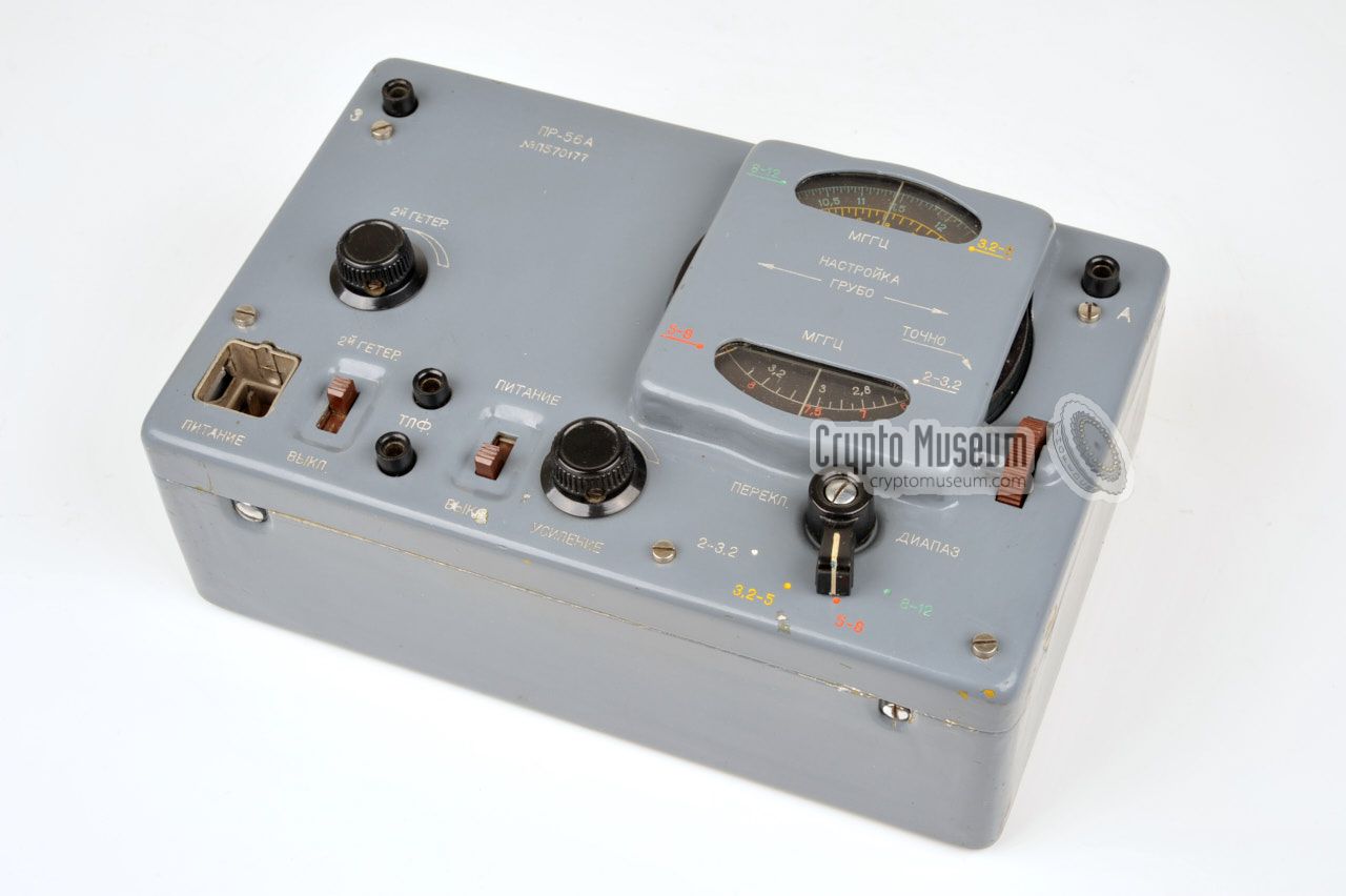
The receiver measures 20.5 x 13 x 8 cm and is housed in a grey metal enclosure.
It has the same form factor as the P-57 transmitter. When it is supplied as
part of the RION spy radio set, the PR-56 is generally identified as BLOCK A.
When the radio was introduced in 1956, it was given the designator PR-56.
When it was later improved or modified, it was named PR-56A.
It is a single-stage heterodyne receiver, built around 7 valves:
RF pre-amp, local oscillator, mixer, 2 amplifier stages, detector and LF amplifier.
It has a sensitivity of 2 - 5.5 mV.
|
|
|
All controls and connections of the PR-56 are located on top of the receiver.
At the bottom left is a 4-pin socket for the LT and HT voltages.
A bit further to the right is a socket for a pair of 4400 Ohm
headphones. An 10 meter antenna wire should be connected to the banana-type
socket at the top right, with a suitable counterpoise connected to the banana
socket at the top left.
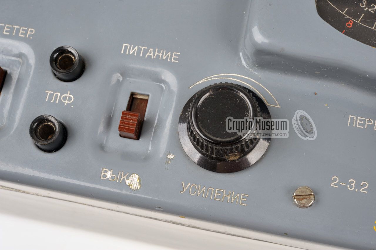
Operating the receiver is straightforward. After connecting a suitable
power source, the receiver is switched ON with a slide-switch at the lower
edge. The 4-position rotary switch at the bottom right is used to select the
desired band segment.
Next, the frequency is adjusted
with the large black dial that extends at both sides of the frequency scale.
A small brown thumb wheel at the far right can be used for
fine tuning.
The audio level is controlled with the Volume adjustment.
|
|
The PR-56A covers a frequency range of 2-12 MHz,
divided over four colour-coded bands:
|
- 2 - 3.2 MHz (white)
- 3.2 - 5 MHz (yellow)
- 5 - 8 MHz (red)
- 8 - 12 MHz (green)
|
Frequency 2 - 12 MHz - 4
Sensitivity 2 - 5.5 µV Headphones Type TA-4, 4400 Ohm Power LT: +1.2V, HT: +80V, G: -4.5V
|
|
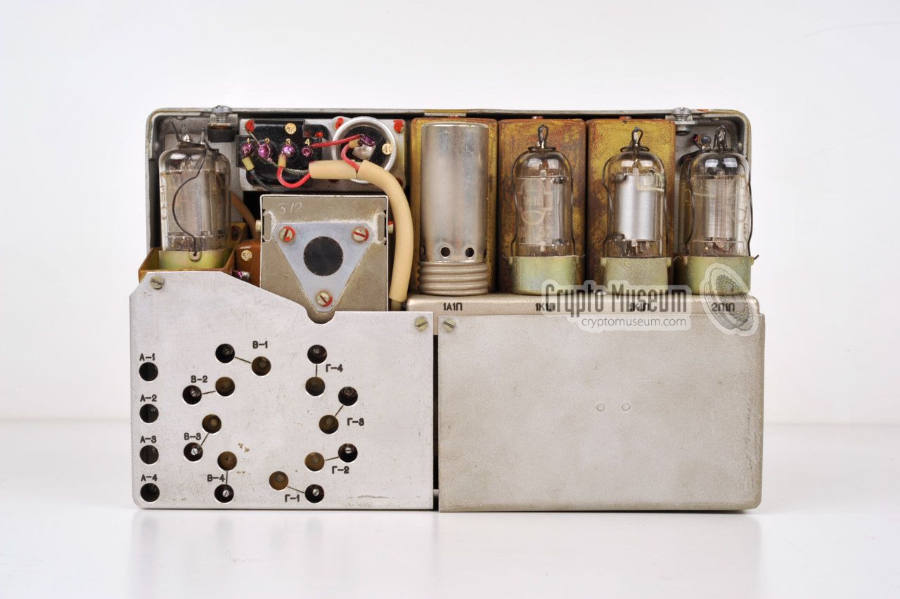
The interior of the PR-56A is easily accessible. Simply loosen the four
screws at the edges (two at the front and two at the rear), and remove
the case shell. The frame that carries all components is mounted to the
front panel, so that the entire receiver can be
lifted from the case as a
single unit.
|
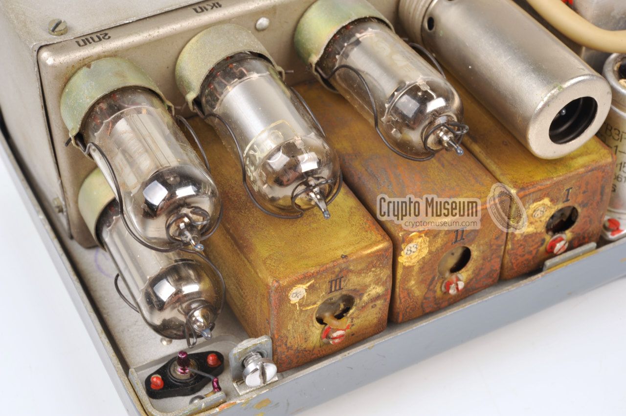
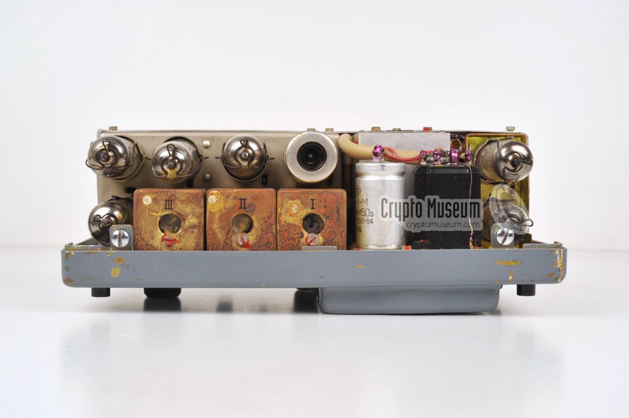
The image on the right shows the interior of the receiver as seen from
the top right. All seven valves (tubes) are directly accessible so that
they can easily be swapped in case of a defect. The types are printed
on the chassis for reference.
The metal shield with the holes,
at the far right, covers the band selector.
Each band has its own test point and can be calibrated individually.
The metal shield at the left covers the power socket and the audio circuits.
The metal can at the right centre, is the frequency tuning capacitor
that is operated with the large black dial at the front.
|
|
|
Below is the block diagram of the receiver, starting with a passive
band filter at the left. All other stages are built around a single valve
each. After amplification, the RF signal is mixed with the signal from
the adjustable local oscillator (LO) and then amplified in two
IF stages. The signal is then detected and amplified to headphones level.
Check out the circuit diagram here.
Considering the fact that this receiver was developed and built in 1956,
it is extremely well built, to the highest standards of the era. This
particular unit has been preserved well and is in near-mint condition.
The RION transmitter, that was introduced a year later, is of similar
build quality.
|
Device Spy radio receiver Purpose Agent communication Country USSR Frequency 2 - 12 MHz - 4 (see below)
Sensitivity 2 - 5.5 µV Headphones Type TA-4, 4400 Ohm Power LT: +1.2V, HT: +80V, G: -4.5V
|
|
The PR-56A covers a frequency range of 2-12 MHz,
divided over four colour-coded bands:
|
- 2 - 3.2 MHz (white)
- 3.2 - 5 MHz (yellow)
- 5 - 8 MHz (red)
- 8 - 12 MHz (green)
|
|
The diagram below show the pinout of the power socket on the PR-56 receiver,
when looking into the socket from the front of the device.
Note that the metal shell is connected to the chassis (i.e. ground or GND).
It is used as the ground for the HT voltage.
|
- LT in (+1.2V)
- LT out (switched)
- G (-4.5V)
- HT (+75V)
|
|
Note that some receivers have a different wiring of this connector.
This is the case, for example, with the PR-56A. Furthermore, in some
devices the wiring of pins 1 and 2 have erroneously been swapped. Although
this does not affect the operation of the device, it means that the
filaments are powered permanently. Also remember that some devices may have
been amateurised.
Always check the wiring before connecting the PR-56 to a power source.
If the receiver is to be used as part of the RION suitcase (i.e. installed
in the metal frame), you may have to correct some of the wiring.
In this case, use the RION internal wiring diagram
and the battery wiring scheme.
|
The diagram below show the position of the valves when looking at the
opened receiver from the top. The red numbers correspond to the numbers
in the circuit diagram [2].
|
- scAvenger, Technical description of the RION spy set
Website with many photographs. Riga, Latvia.
21 January 2005. Retrieved October 2009. 1
- Louis Meulstee, Wireless for the Warrior, volume 4 2
ISBN 0952063-36-0, September 2004
- Radio Scanner, Radio Station 'RION'
Website (Russian). Retrieved May 2016.
|
-
Website no longer available in 2016.
-
In this book the receiver is erroneously called GR-56A.
|
|
|
|
Any links shown in red are currently unavailable.
If you like the information on this website, why not make a donation?
© Crypto Museum. Created: Thursday 01 October 2009. Last changed: Monday, 22 January 2024 - 16:03 CET.
|
 |

|
|
|


