|
|
|
|
|

|
|
Receiver Cold War UK
Clandestine receiver
The Mark 301 (Mk.301) was a miniature
valve-based receiver for clandestine activities.
It was designed in 1954 by SG Hart (VK5HA) when working for
HMGCC at Borehamwood (UK).
It was intended as a replacement
for the war-time MCR-1 and was built around
5 subminiature valves.
|
The Mk.301 is suitable for all frequencies between 500 kHz and 18.5 MHz,
divided over four ranges.
Unlike the MCR-1, that needed four different
coil packs, the Mk.301 comes with a single coil pack that can be inserted
in four different ways, marked with the numbers 1-4.
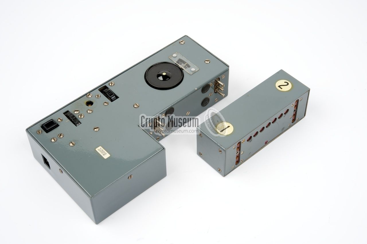
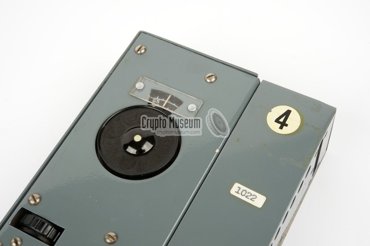
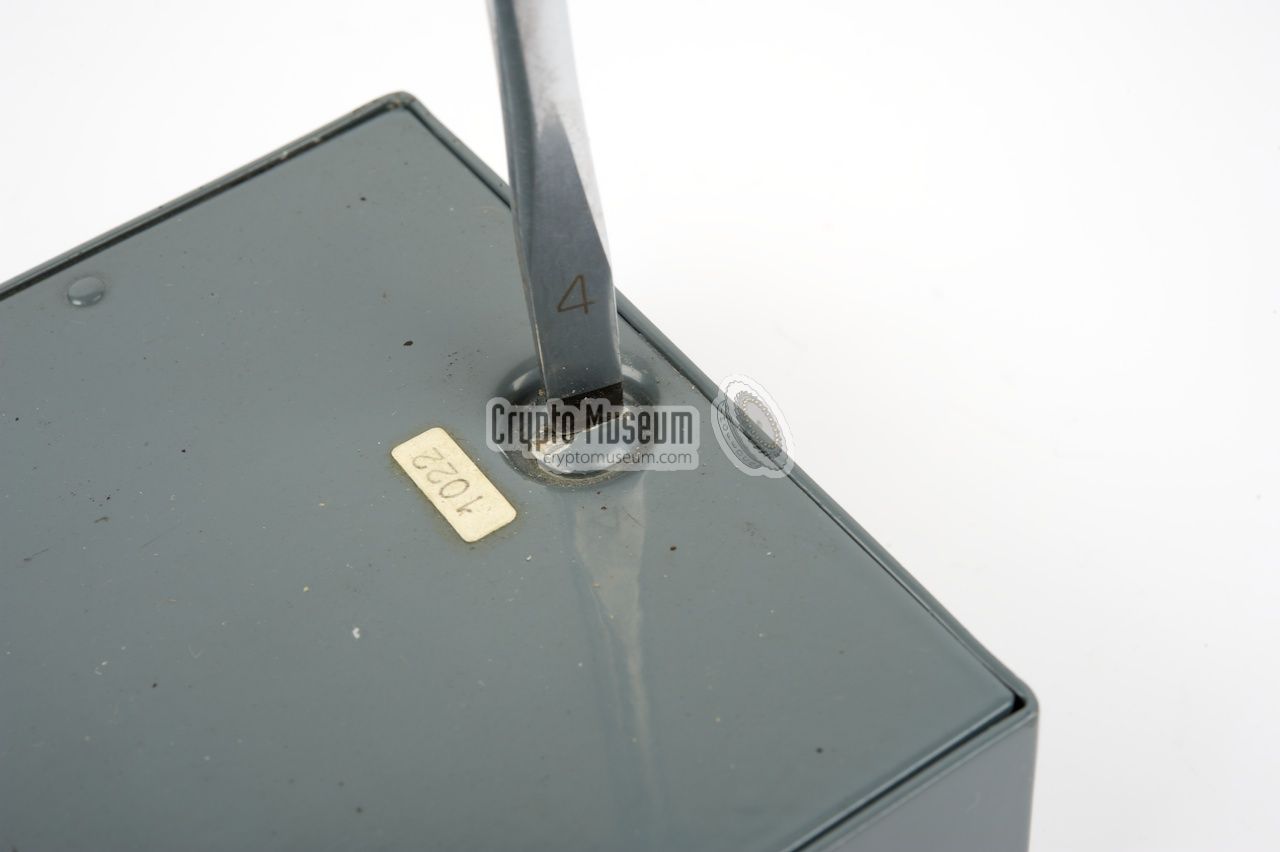
The image on the right shows a typical Mk.301 receiver with detached
coil pack. The case of the receiver is constructed in such a way that the
coil pack fits inside the 'missing corner'. The number in the top right
corner corresponds with the band number (1-4) that is being used.
|
|
|
The coil pack in the image above is positioned in such a way, that band
number 2 will be used when the coil is plugged-in.
A battery pack or an external power pack should be used to supply the
necessary 1.5V (LT) for the filaments and 67.5V (HT) for the valves.
It is connected to a 4-pin socket
at the bottom of the receiver
(here visible at the front). A suitable (wire) antenna and earth lead (ground)
can be connected at the top of the receiver (not visible in the image above).
The receiver came with an accessory box of approx. the same
size as the receiver, that was also used as the battery pack.
Alternatively, the optional Mk.301PP Power Pack
could be used as a mains power supply.
It could be fitted inside the battery box.
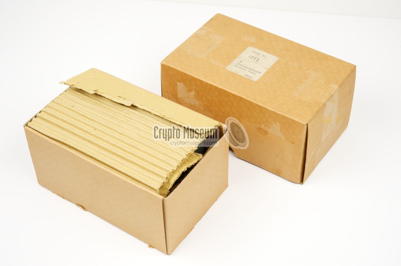
The complete kit (without the power pack) was distributed in a
small carton box
that also contained the user instructions.
The receiver was intended for several services that were controlled by
Hanslope park (UK), but it was later adopted for use by the Army's
Special Forces as well. The Mk.301 was replaced in 1970 by the fully
transistorised Mk.328
that had a band selector rather than a separate coil pack.
A nice article about the Mk. 301 by Wim Kramer (1992, Dutch)
is available for download below
[1].
|
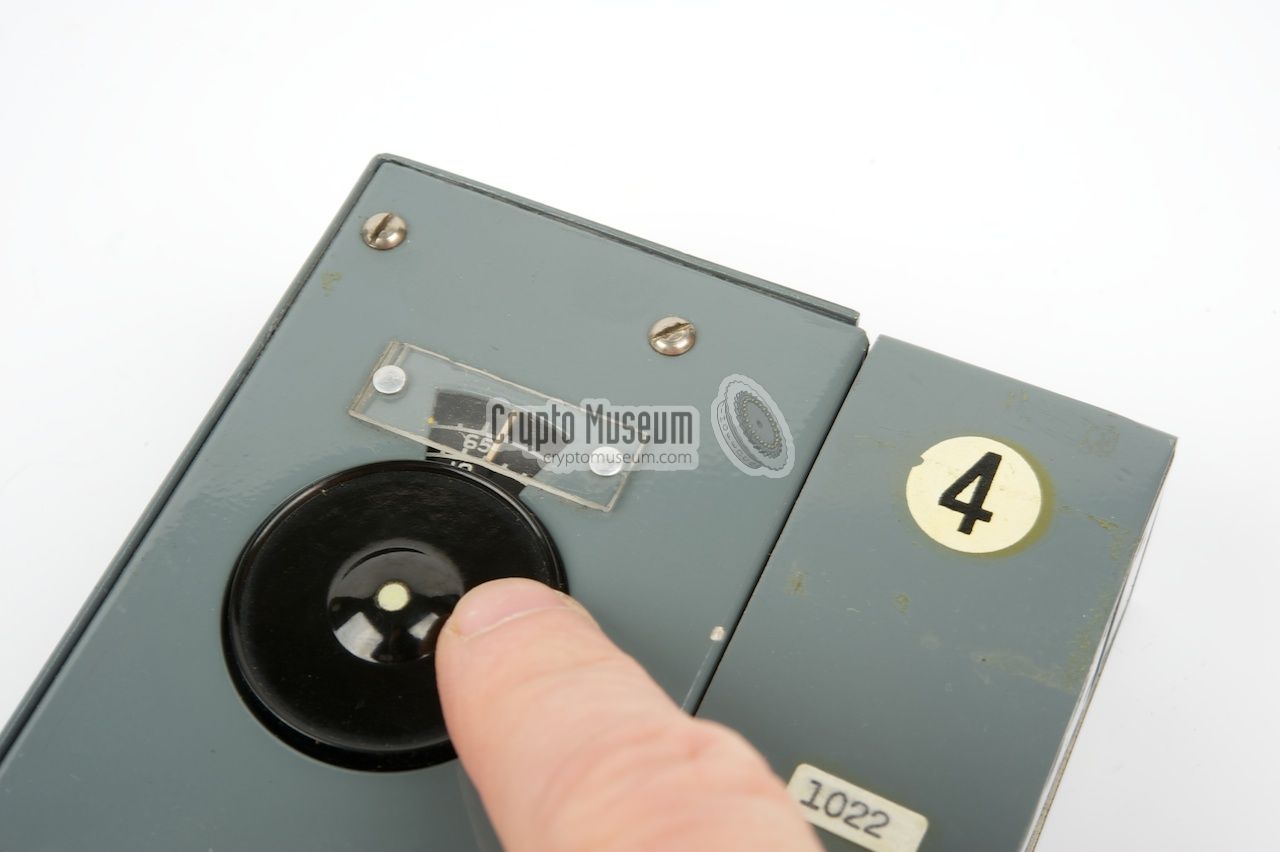
The image below shows the controls of the Mk.301 receiver.
The receiver has only three adjustments: volume, BFO and tuning,
and is extremely easy to operate. At the right is the coil pack
that can be mounted in four different ways, each representing
one of the frequency bands.
Connections are at the front (power), top (earphones) and rear
(antenna and ground). The receiver is turned on as soon as power
is supplied to the 4-pin socket at the front. Turn the volume
control to an appropriate level and use the frequency dial to
select the desired frequency.
|
|
Weighting just 1kg and measuring just 17 x 9 x 3.5 cm,
the Mk.301 is one of the smallest valve-based receivers ever built.
Five subminiature valves are used to create a
superheterodyne receiver with great sensitivity.
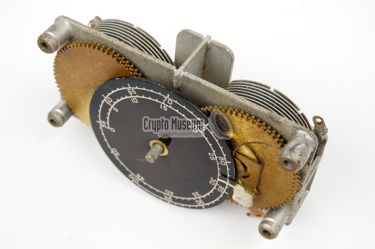
For frequency adjustment, the designer (SG Hart) invented a revolutionary
2-section side-by-side tuning capacitor
with spiral scale, that fitted the slimline case.
|
The receiver is tuned by rotating the large black dial
with one finger.
It has a linear scale and is very smooth in operation.
A set of tables
inside the top lid of the battery box converts the
linear scale into the actual receiving frequency.
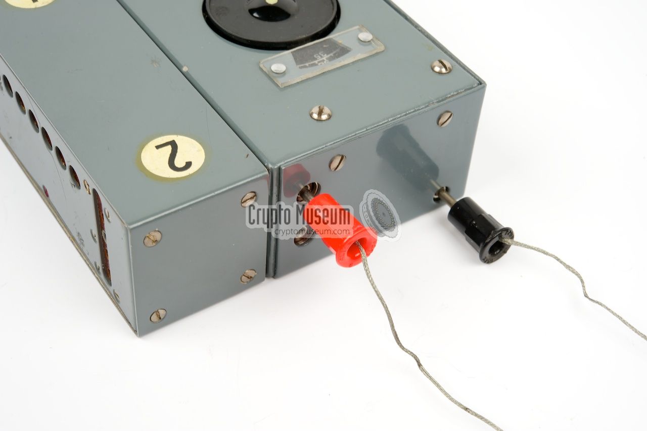
Although the receiver can use a single short wire as antenna,
it works best with a longer wire plus a suitable earth (counterpoise).
The antenna inputs and the earth connection are at the
top of the receiver. The sockets are visible as
three small holes.
For the reception of strong signals, a separate
attenuated antenna input
is available.
|
|
|
|
A suitable wire antenna
and earth wire with the appropriate plugs
were supplied with the kit. They were usually stored inside the
accessory box.
The antenna wire is 17m long and has to be as free as possible.
The earth wire is 3m long and has an alligator clip at the other end,
allowing it to be connected to, say, the water pipe.
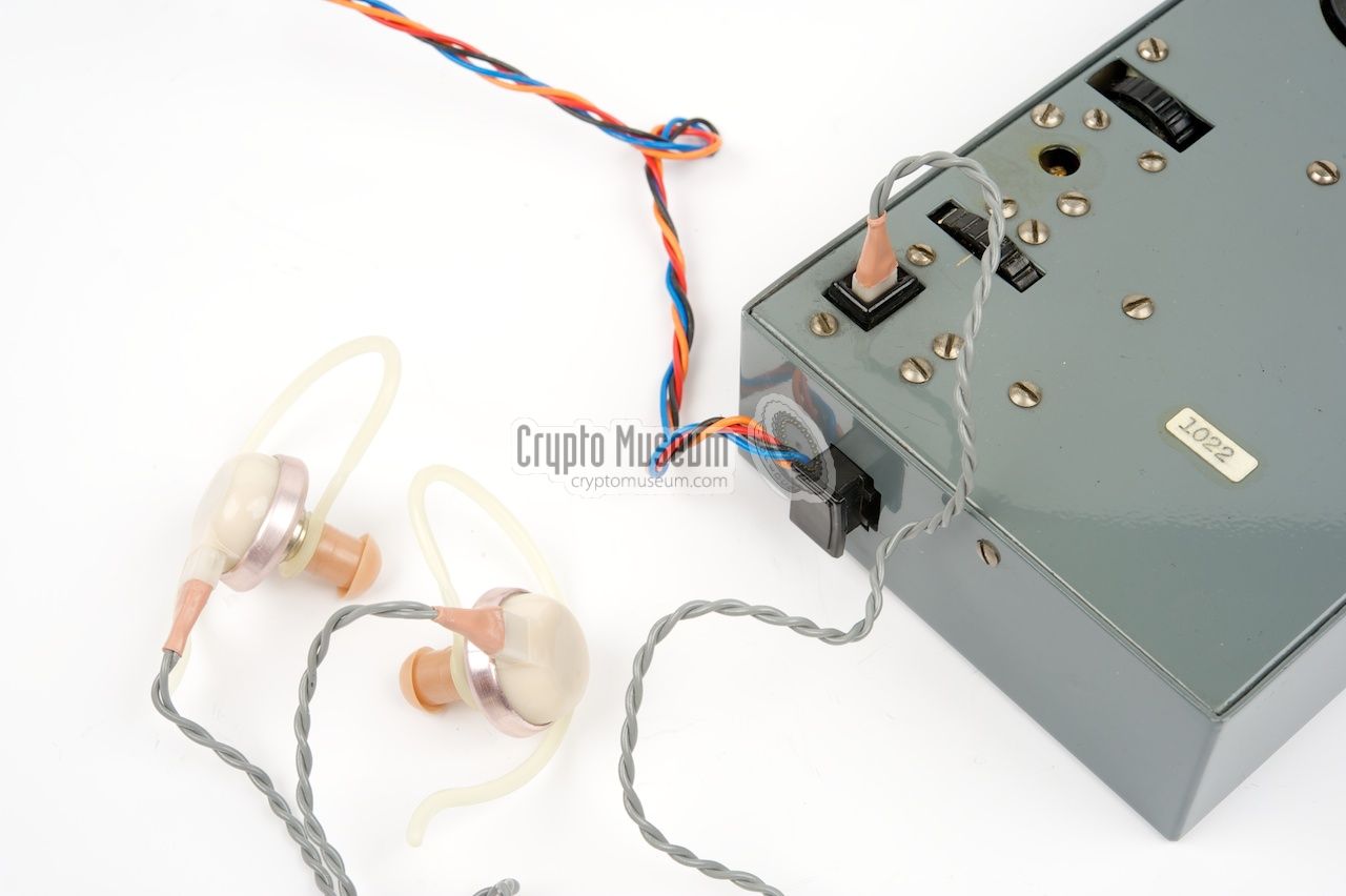
The AF output amplifier delivers a 1mW signal into a pair of high-impedant
(15kΩ) earphones,
similar to the ones that were used for hearing aids.
|
|
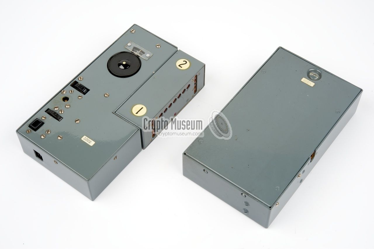
The Mk.301 came with a metal box of the same size
as the receiver itself.
The box contains the accessories, such as the
earphones.
When empty, the accessory box could be used as the battery
box, taking a single 1.5V battery for the filaments and a 67.5V DC
battery for the HT voltage.
|
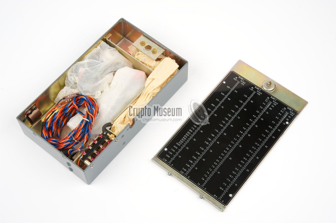
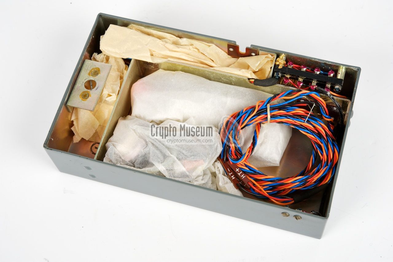
The contents of the accessory box can be accessed by
removing the top lid.
The inside of the lid
contains four tables, one for each coil. The table
converts the linear scale of the Mk.301 into the actual frequency,
similar to the MCR-1.
The image on the right shows the accessory box with its top lid taken off.
Some accessories are packed in thin white paper.
The empty accessory box can be used to create an LT/HT battery box.
A colourful fixed 4-wire cable attaches the battery box
to the receiver. It connects to the 4-pin socket
at the bottom of the receiver.
|
|
|
|
A separate power cable allows the Mk.301 receiver
to be connected to an alternative power source, such as a pair of (LT/HT)
batteries or an external power supply unit.
Also in the accessory box is a pair of high quality
earphones, similar to
the ones that were used in hearing aids of those days,
and a piece of cardboard with the antenna and earth wires.
|
|
|
Power Supply Unit
Mk.301PP
|
|
|
|
Some Mk.301 units were supplied with a drop-in power supply unit (PSU)
allowing the Mk.301 to be powered from the mains rather than from batteries.
When present, the Mk.301PP AC mains adapter could be placed inside the
accessory box and fitted precisely
in the space that was normally used for the batteries.
The mains power cable leaves the case through a hole in the side.
|
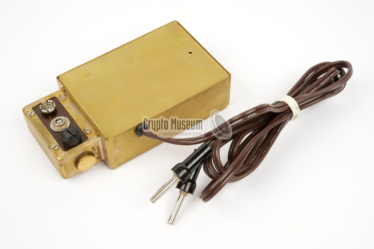
The image on the right shows a good-looking replica of the original
Mk.301PP power pack. It was built to the original specifications and sizes.
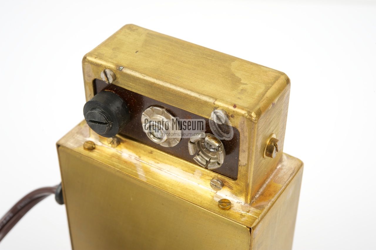
It has a rectangular shape with a 'blob' at one end.
The blob replaces the 1.5V filament battery and has a contact at either side,
that directly mates with the contacts inside the battery box.
The two 'flying' contacts for the 67.5V HT battery should be
connected to the sockets
on the top surface of the blob.
To the right of the two HT terminals is the mains primary fuse.
|
|
|
|
When the Mk.301 PP
is mounted in the way described above,
the case can be closed again.
The mains lead can be fed through a hole in the right side of the
battery box, together with the 4-colour wiring to the receiver.
It connects to the mains by means of two banana-type plugs.
|
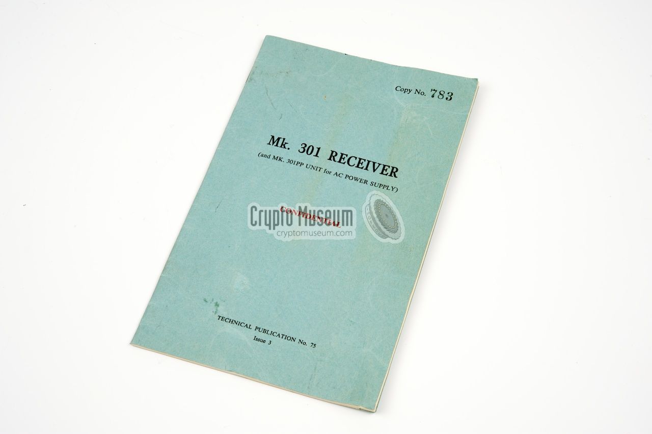
The Mk.301 receiver came with a small booklet with instructions
on how to use and maintain the receiver. The booklet also
contains the full circuit diagrams of both the receiver
and the (optional) Power Supply Unit Mk.301 PP.
Two variants of the manual are currently known: issue 2,
that came in the brown envelope shown on the right, and
issue 3, that had a blue cover. Apart from a few minor differences,
this manual is identical to the earlier issue 2 release.
Issue 2 is available for download below [A].
|
|
|
|
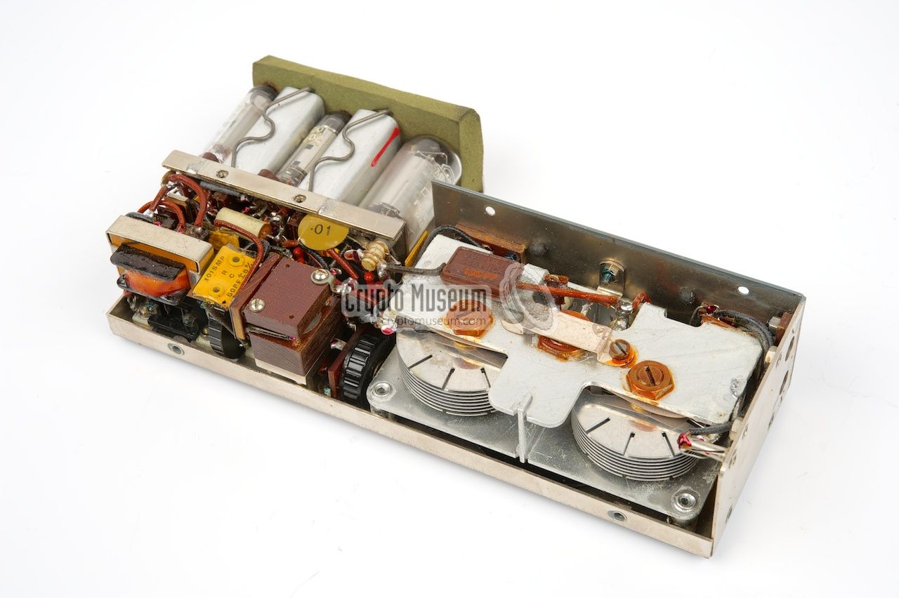
The Mk.301 receiver can be opened by removing 8 small bolts at the sides
and a further 2 at the rear. The outer case shell can then be removed completely,
whilst all components stay together in the main frame.
The image below shows the interior of the Mk.301 after removing the outer shell.
|
At the front right is the famous
two-section side-by-side tuning capacitor.
The two sections are driven simulataneously by the frequency dial
via a set of cog wheels (not visible here).
At the left rear is a small sub-frame
holding the five subminiature
valves and some adjustable inductors. A piece of foam at the rear
prevents the valves from falling out of their sockets when the receiver
is transported. The remaining passive components
are mounted at the bottom of the sub-frame, visible here at the front left,
with the output transformer at the corner.
|
|
|
The coil pack can be attached in one of 4 ways, to the
contact pins behind the tuning capacitor.
Inside the coil pack is a
set of coils and adjustable capacitors
that have been calibrated for the appropriate frequency bands.
The coil pack consists of
two halves that each hold the
components for two bands. The adjustable coils and trimmers are
accessible through holes in the case.
|
- Principle: 4-valve super-heterodyne receiver, with BFO for CW and Phone reception
- Frequency range: 500 kHz - 18.5 MHz
- IF frequency: 465 kHz
- AF output: 1mW into 15kΩ
- Power supply: 1.5V LT (125mA) and 67.5V HT (12mA)
- Mains power supply (optional): 100-250V AC 50/60Hz
- Antenna: 17m wire
|
- 500 - 1250 kHz
- 1.20 - 3.25 MHz
- 3.10 - 7.77 MHz
- 7.75 - 18.5 MHz
|
- 1 x DK96 (local oscillator mixer)
- 2 x DF72 (IF amplifier and BFO)
- 1 x DAF70 (Detector, AFC, AF stage)
- 1 x DL75 (Audio output amplifier
|
- Receiver
- Coil Box Assembly
- Battery Box Assembly
- Battery Lead Assembly
- Earth Lead Assembly
- Areal Lead Assembly
- Aerial & Earth Lead Spool
- Phones Complete
|
-
Reproduced here by kind permission from the author Wim Kramer.
|
|
|
|
Any links shown in red are currently unavailable.
If you like the information on this website, why not make a donation?
© Crypto Museum. Created: Saturday 03 October 2009. Last changed: Friday, 29 April 2022 - 15:25 CET.
|
 |

|
|
|