|
Receiver UK WWII MBLE version → SOE
Miniature Communications Receiver
MCR-1 is a modular valve-based MW/SW clandestine receiver,
developed in 1943 by Captain John Brown of the
Special Operations Executive (SOE)
and built by Philco in the UK. It was intended
for use by the SOE and
Special Forces (SF), and was later adopted by the Army as well.
The internal designator for the receiver was Type 36/1,
but it is commonly known as Midget Communications Receiver MCR-1. 1
It was used stand-alone, but also as part of a complete Jedburgh
radio set.
|
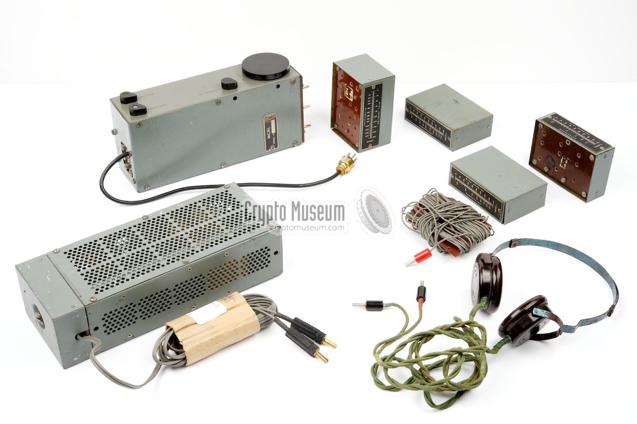
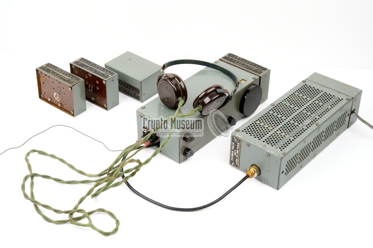
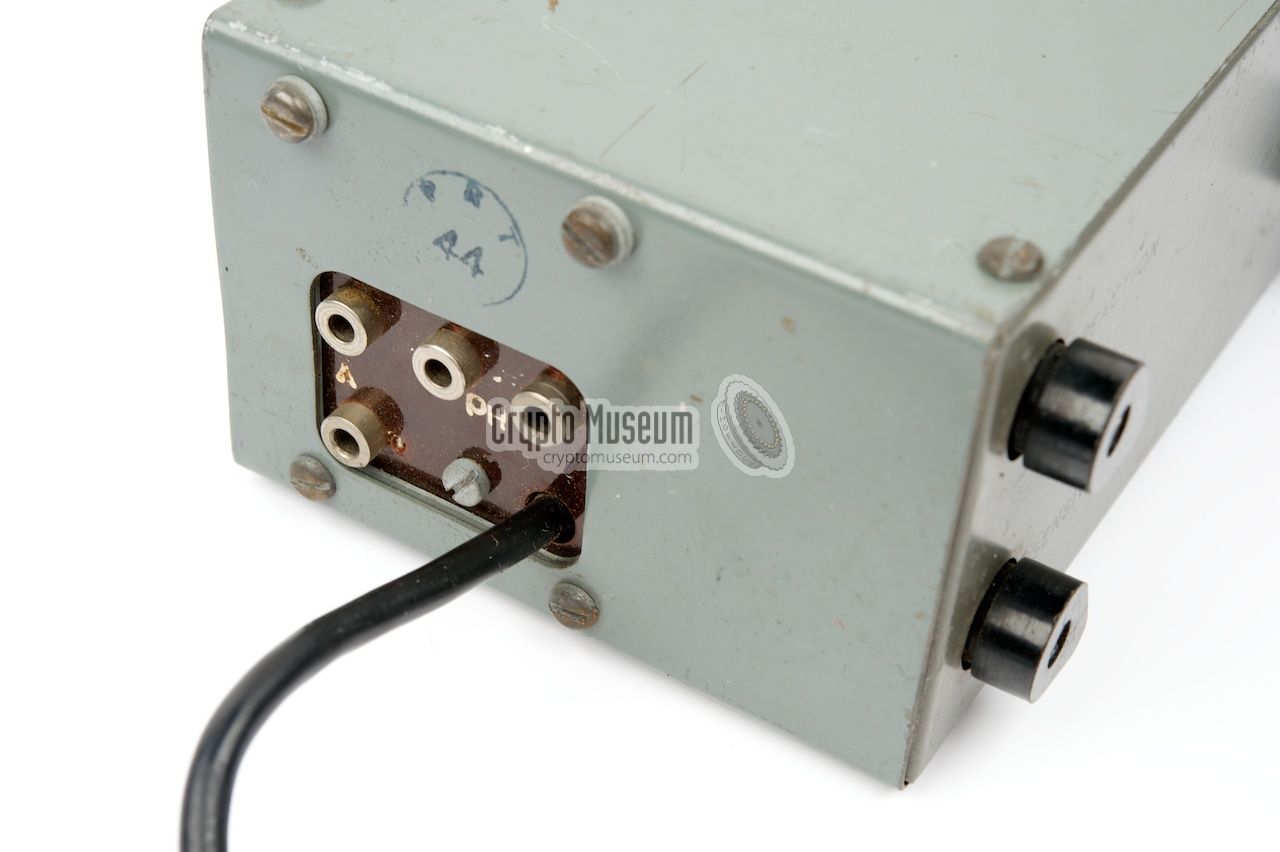
The MCR-1 consists of a rectangular receiver,
with four plug-in coil packs that can be attached at one end,
a separate Power Supply Unit (PSU)
of the same size as the receiver, and various accessories.
The sets were distributed in water-tight sealed
tinned-steel biscuit tins,
which is why they got nicknamed Biscuit Tin Receiver.
The receiver has a frequency coverage of 150 kHz - 1.6 MHz (broadcast band)
and 2.5 - 15 MHz (short wave), divided over four ranges.
It can be powered by a combined battery pack (7.5V/90V) or by the
external mains AC/DC PSU.
|
|
|
During WWII
the MCR-1 became a popular receiver with resistance
groups in several European countries.
It was built under licence by Philco in the UK,
and many were dropped over occupied Europe for the
reception of the 'civil' broadcasts of the BBC that carried
the latest news in various
languages, speeches of the British Prime Minister and other heads of states
and often coded messages for the resistance (e.g. to confirm the arrival
of a VIP or an upcoming dropping).
The receiver was also used as part of complete radio stations, such
as the Type 46/1 (Jedburgh Set) and
the Type 48/1 (Nicholls Set).
Production of the receiver started in late 1943, and by the end of the war
more than 30,000 units had been made [1].
After the war, the MCR-1 became a desired collector's item, as only a modest
quantity had survived.
During the Cold War,
the MCR-1 was cloned by MBLE for the Belgian
Stay Behind Organisation (SBO).
In 1954, the rather large receiver was succeeded by the much smaller
Mk.301 that was built with miniature valves (tubes).
|
 |
-
According to the manual [A], MCR is the abbreviation of Midget
Communications Receiver. In some documents however — such as the
instruction card [B] — it is listed as Miniature Communications
Receiver.
|
The diagram below provides a quick overview of the controls and
connections on the body of the receiver (here shown at the centre),
the Power Supply Unit (PSU)
and the coil packs. The receiver has a
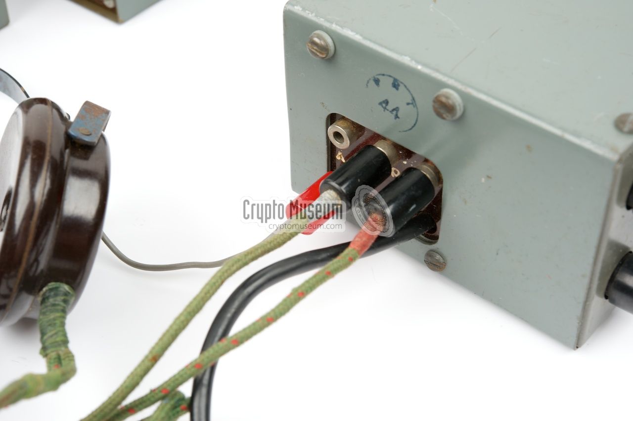
fixed wire that should be connected to the power socket of the PSU
(here shown at the left).
(left)}
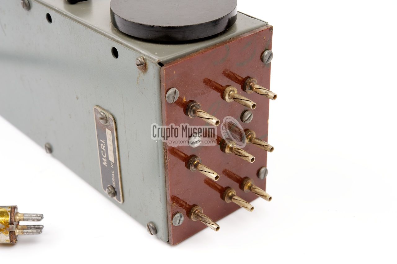
The receiver has a set of contact pins at the right end, on which
one of the (four) coil packs can be installed. Depending on the
desired frequency band, one of these coil packs must be installed
on the receiver. The thickest coil pack (at the far right) is for
reception of the MW broadcast band.
|
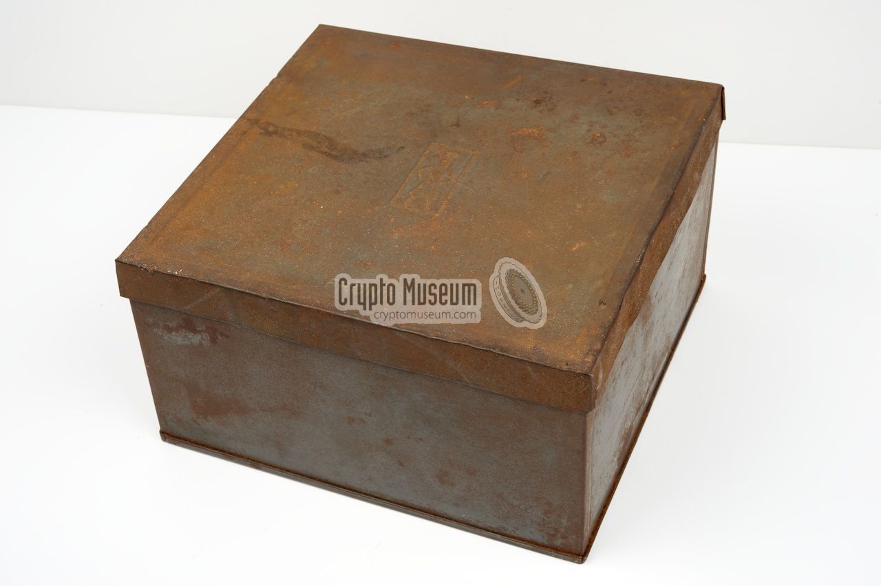
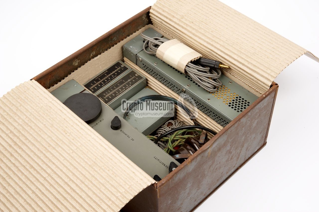
The MCR-1 and its PSU were constructed in such
a way that they could be stored inside a standard biscuit tin of those days.
The image on the right shows an original (now rusty) biscuit tin with a complete
MCR-1 set, protected by cardboard. The receiver and the PSU are each stored
at one side, with the accessories in between them.
Bicuit tins of the appropriate size were made by Huntley & Palmer
in Reading (UK) and also by Meredith & Drew (M&D) in London (UK).
The size of a bicuit tin was approx. 23 x 22 x 12 cm.
|
|
|
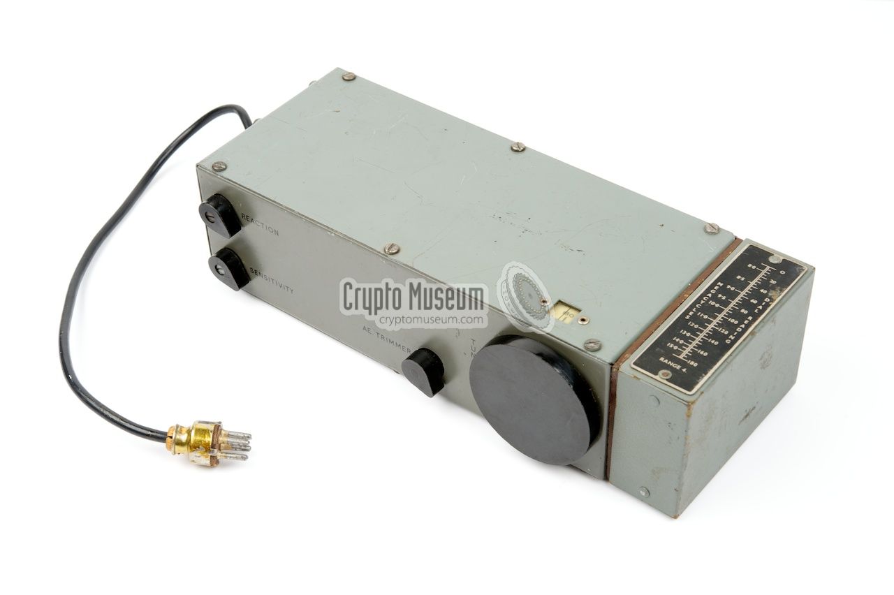
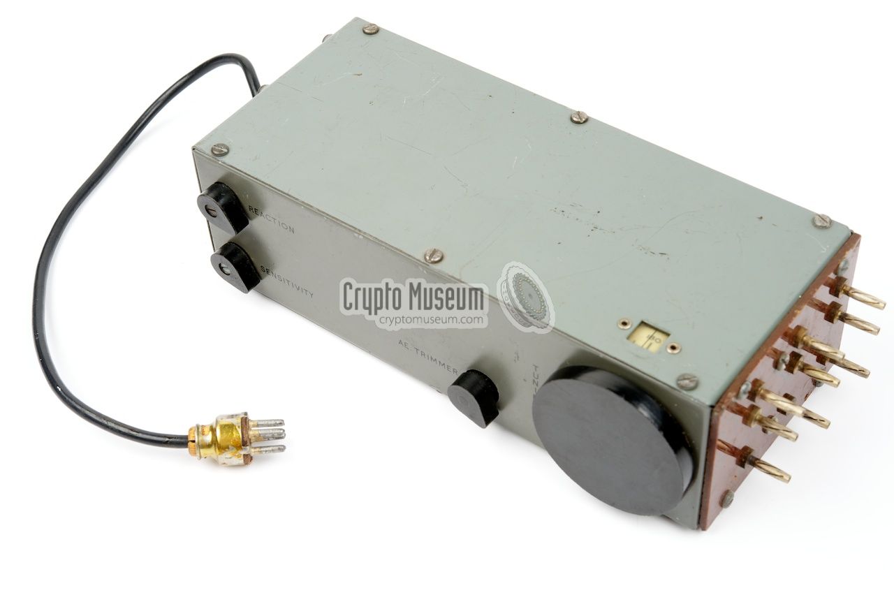
The image on the right shows the bare receiver. The flying lead
at the left is for connecting
a battery
or the PSU. At the right
is the receptacle
(i.e. the sticking-out pins) for the coil pack.
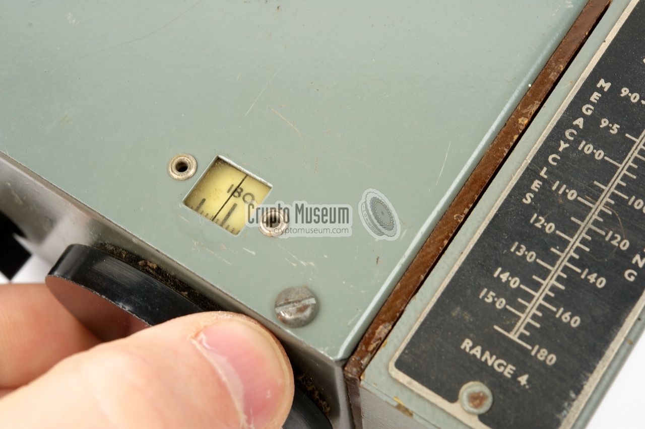
The controls are at the front. The large knob on the right is the tuning
dial. Just above the dial, is a small window with a
linear scale.
Each coil pack has a frequency conversion table
on its body.
The receiver is built around 5 valves (4x 1T4 and 1x 1R5)
and has an IF of 1730 kHz, which lies in between range 1 and 2.
Sensitivity is approx. 10 µV (for 1 mW audio output)
and the AF power is approx. 5-8 mW into 800 ohms headphones.
|
|
|
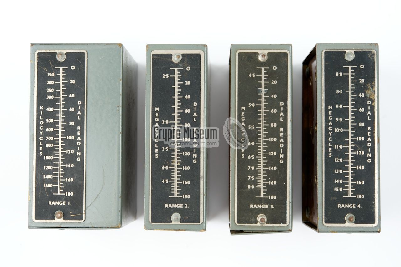
The MCR-1 covers all frequencies between 2.5 and 15 MHz, divided
over 3 frequency ranges, plus the domestic MW band from 150 kHz to 1.6 MHz
in a single-span. 1
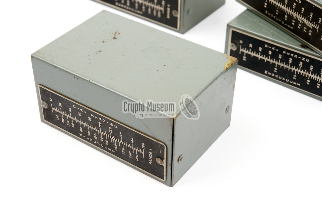
A tuning coil is fitted to one end of the receiver and four such coils
were supplied, one for each frequency band.
The tuning scale is linear and a suitable frequency conversion scale
is printed on an metal plate
on each coil. On some of the early
production runs of the MCR-1, the conversion table was
printed on paper.
Such tables will have faded over time and are often hard to read.
|
|
|
-
Coil pack (1) is somewhat thicker than
the other ones and uses the so-called single-span principle to
cover the entire MW broadcast band.
|
For portable use, the MCR-1 can be powered by a combined battery pack
that supplies 7.5V/90V. Such (dry) batteries were readily available at
the time and had a 4-pin socket that mates
directly with the fixed lead of the receiver.
The unit draws approx. 50 mA from the 7.5V LT rail
and 5 to 8 mA from the 90V HT rail.
For domestic use, the MCR-1 was powered from the mains.
The manual provides instruction on how to use improvised batteries
when the original battery pack is in short supply.
|
|
|
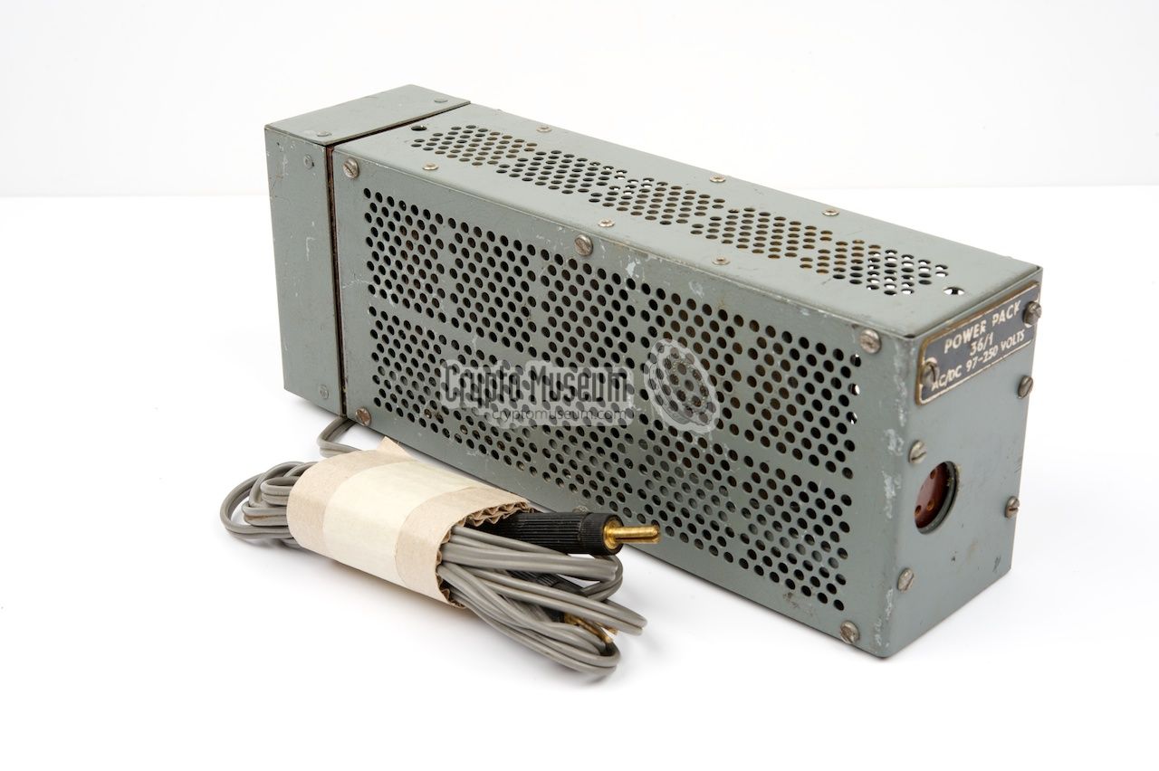
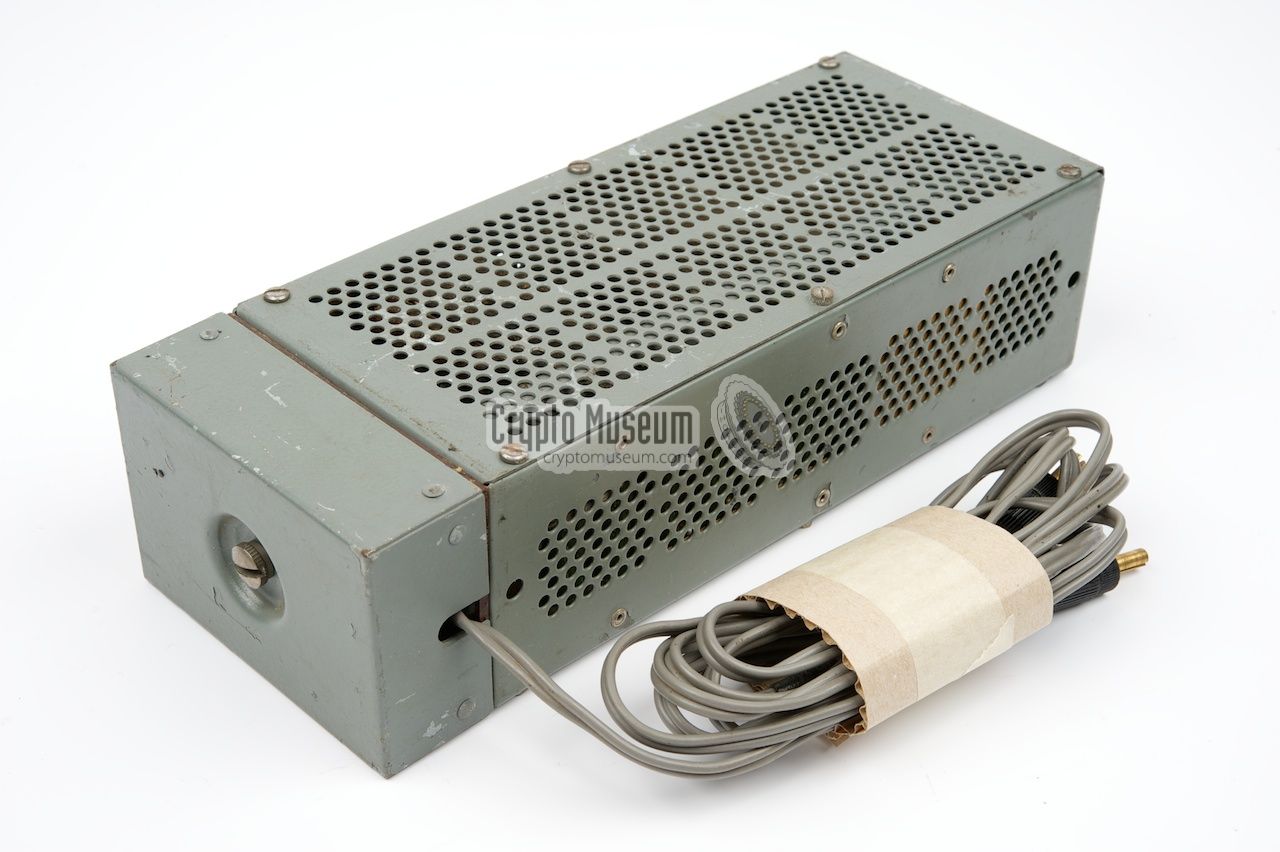
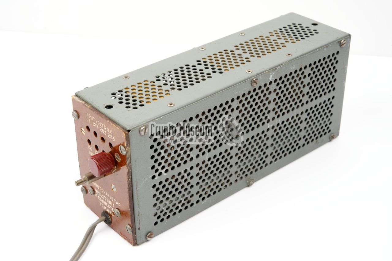
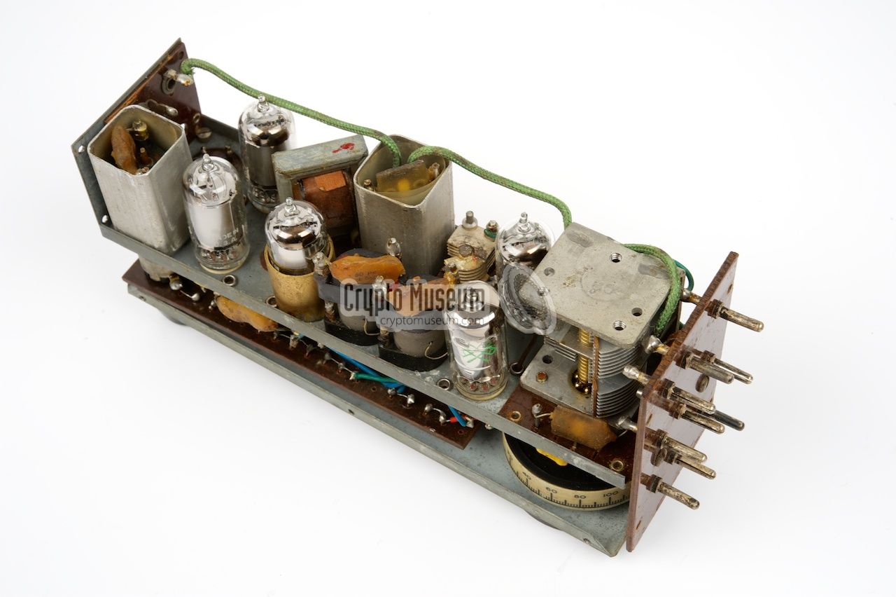
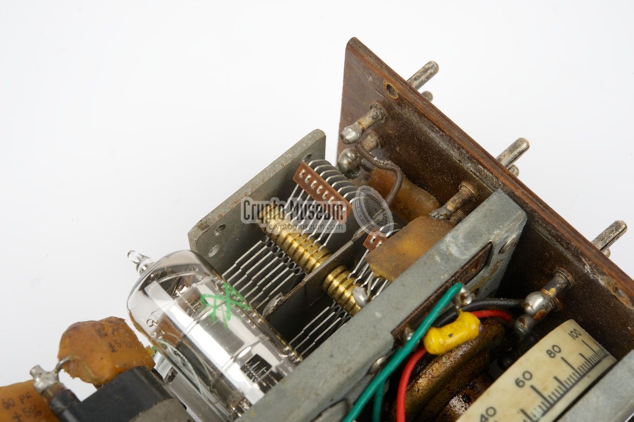
A suitable Power Supply Unit (PSU)
was supplied with the set, allowing
the MCR-1 to be powered from a wide range of mains voltages, both AC and DC.
For connection to the AC mains, an autotransformer with multiple taps is used [2].
For connection to the DC mains, an
array of power resistors is used.
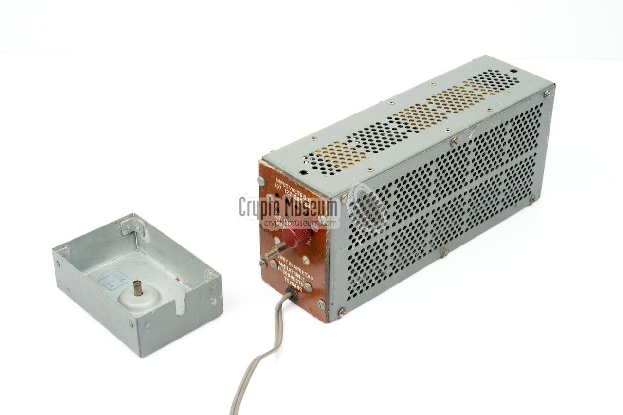
The voltage selector
is located behind a metal cap at one end of the PSU.
The desired AC or DC voltage can be selected, by placing the screw-terminal
in the corresponding hole. Mains power was usually 'tapped' from the light bulb
using an adapter.
|
|
|
WARNING — Please note that autotransformers are potentially
dangerous, as they do not isolate, but connect the receiver directly to the mains.
As a result the chassis of the receiver may carry the mains voltage.
If this happens, the mains power plug should be reversed. For safety reasons
it would be better
though, never to use the original power supply, and use a battery or a
modern PSU instead.
For a good reception it is necessary to connect a proper
(wire) antenna
to the socket marked 'A' and a sufficient ground (counterpoise) to the
socket marked 'E' (earth).
A suitable wire antenna, wound on a Paxolin
card, is supplied with the set. The manual
even demonstrates the portable use of a the MCR-1 receiver,
concealed under a regular raincoat.
|
|
|
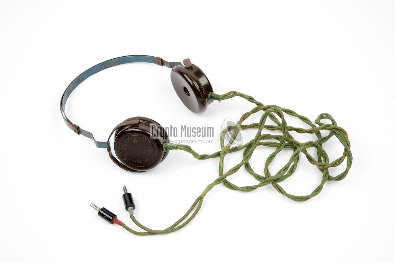
A suitable pair of headphones
is supplied with the set and should be
connected
to the banana-type sockets
at the left side of the receiver, close to the antenna terminals
and the power cable.
The supplied headphones have an impedance of 800 Ohms, to which
the 5-8 mW AF signal from the receiver can be supplied.
|
|
|
The MCR-1 was supplied with a 14-page instruction booklet,
which contained operating instructions, recommendation for the
antenna, examples of covert use and full circuit diagrams.
A copy of the original manual — with a 4-page supplement —
is available for download below.
➤ Download the manual
|
|
|
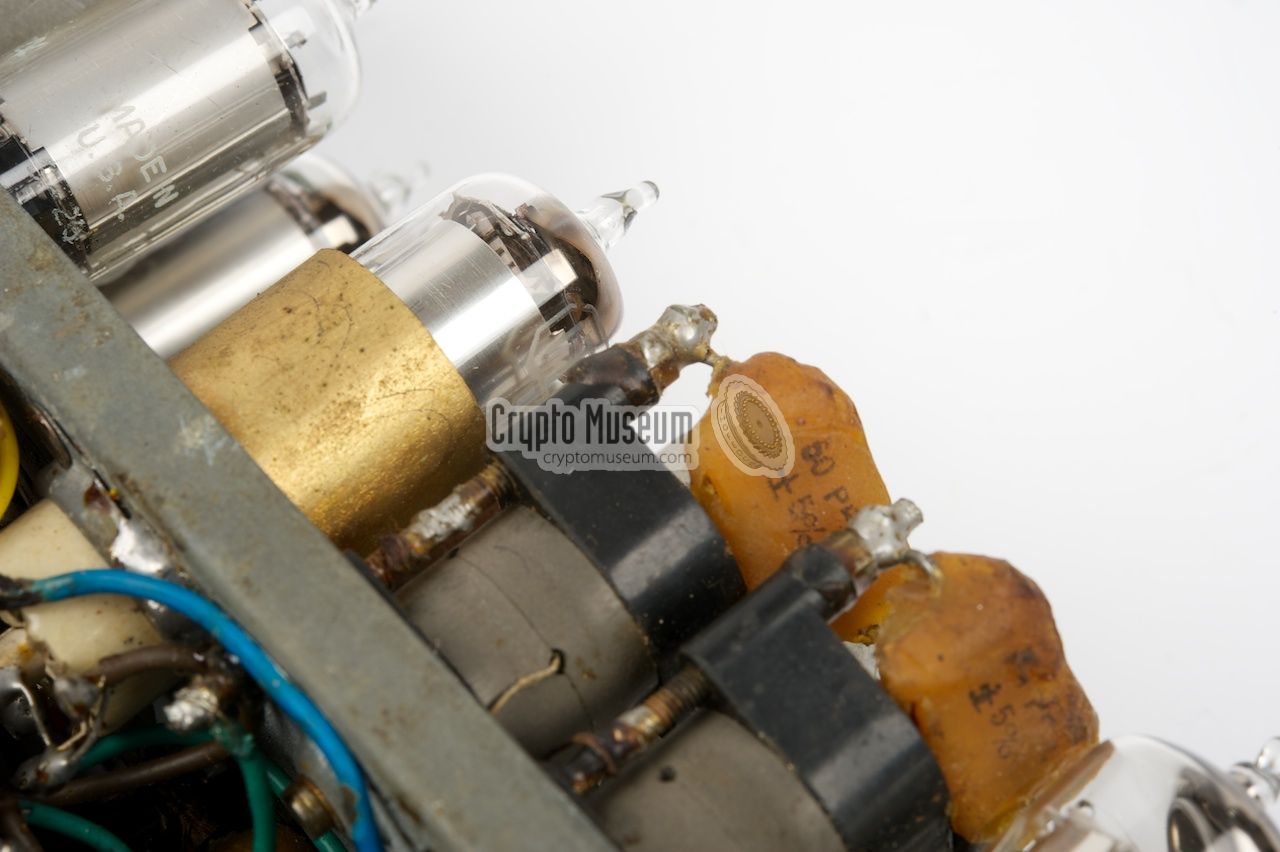
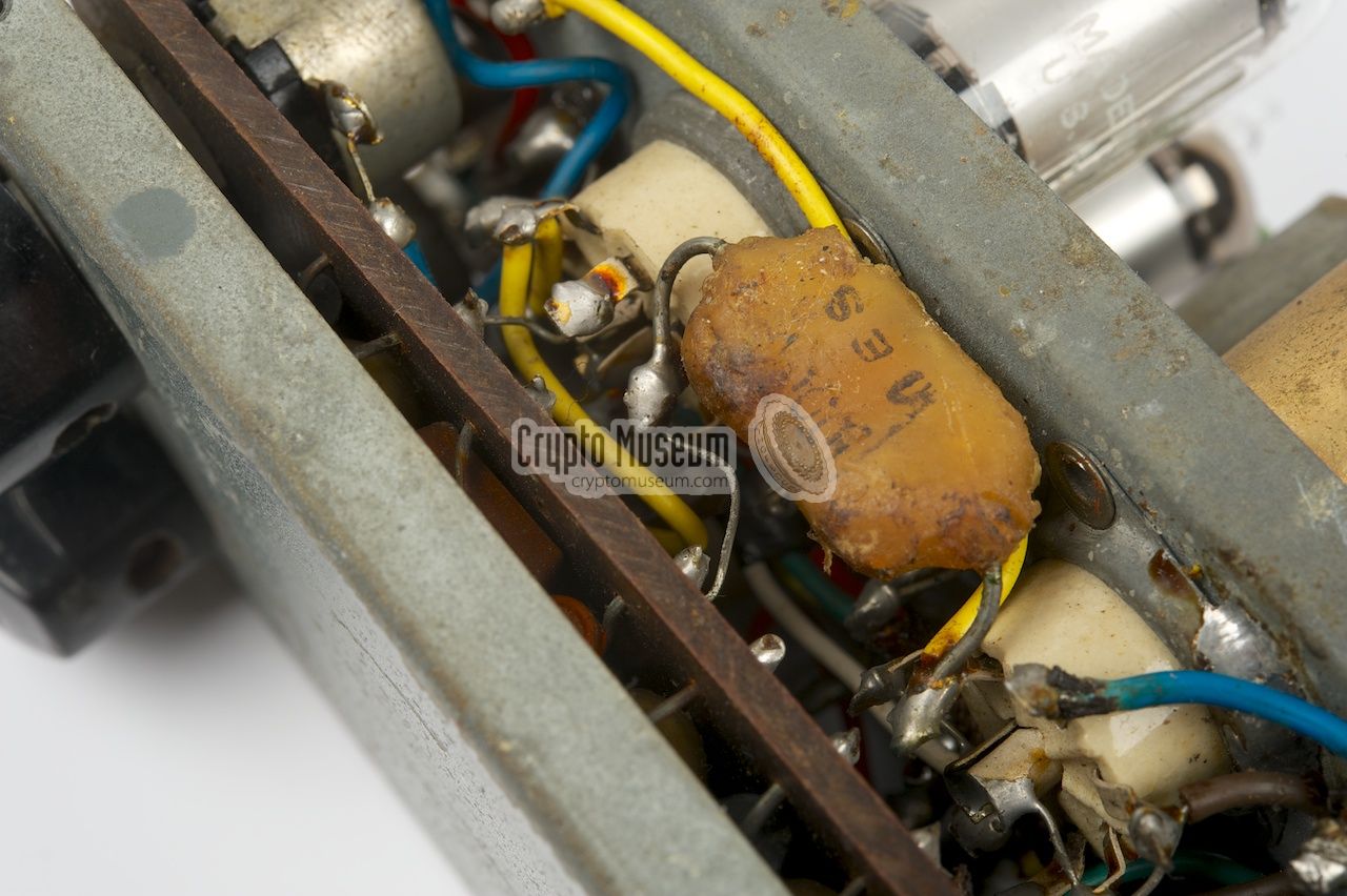
The interior of the MCR-1 can be accessed by removing the 20 bolts
around the edges of all sides. The bottom and the U-shaped case can then
be taken off. Despite the rather simple exterior, the interior of the MCR-1
is rather complex and well-built.
The image on the right shows the interior of a typical MCR-1.
The five valves are clearly visible. At the right is the large tuning
capacitor.
|
|
|
|
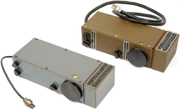
After the war, in the late 1950s, copies of the MCR-1 were produced by
Manufacture Belge de Lampes Electriques (MBLE), a subsidary
of the Dutch electronics giant Philips.
Apart from a few mechanical
and components changes, the MBLE-version
was electrically identical to the original.
|
The image on the right shows such a post-war MBLE copy of the MCR-1 (Bg).
The unit is much better built than the war-time version and uses
higher-grade components. Furthermore, the case and the coil packs are
painted in a brown wrinkle-finish. The text on the body is in French
and the knobs have a more modern look.
The MBLE version of the MCR-1 was supplied in a green canvas carrying bag
that had space for the coil packs, headphones, antenna, ground wire and
the battery pack, and came with a loop antenna.
This receiver was intended
for the secret Belgian
Stay Behind Organisation (SBO).
|
|
|
The MBLE receivers came without a mains power supply unit, so
it is likely that they were meant for operation with a battery pack. There is enough
free space in the canvas bag to carry a suitable battery. It is also
likely that the MBLE-version of the MCR-1
was intended for portable use, as it has a much longer power cable,
allowing the battery to be carried in the other pocket of the coat.
➤ More about the Belgian MCR-1
|
The image below shows the pinout of the power socket of the Power Supply Unit (PSU).
Please note that the common line (LT-/HT-) is directly connected to the mains when
using the original PSU. This is potentially dangerous
and can even be lethal.
Do not use the original PSU unless you know exactly what your are doing.
It is far better to use batteries or an alternative (safe) PSU.
|
Device Clandestine radio receiver Model MCR-1 Designator Type 36/1 Developer SEO, Capt. John Brown Manufacturer Philco (UK) Country UK Year 1943 Users SOE, resistance groups Frequency 150 kHz - 1.6 MHz, 2.5 - 15 MHz Bands 4 (see below) IF 1730 kHz Valves 5 (see below) Power Dry battery pack LT: 7.5V, HT: 90V, or mains PSU Current LT: 50mA, HT: 5-8mA Modulation AM R/T, CW Dimensions Bare receiver: 212 x 100 x 60 mm Weight Bare receiver: 1295 g
|
150 kHz - 1.6 MHz 85 x 60 x 40 mm (178 grams) 2.5 MHz - 4.5 MHz 85 x 60 x 30 mm (152 grams) 4.5 MHz - 8 MHz 85 x 60 x 30 mm (154 grams) 8 MHz - 15 MHz 85 x 60 x 30 mm (154 grams)
|
Current AC and DC Input 107, 127, 205 and 235 V Output 90V DC (HT) and 7.5V DC (LT)
|
- MCR-1
- Type 36/1
- Midget Communications Receiver MCR-1
|
|