|
|
|
|
|

|
|
← CZ Cold War
Long range 50W short wave transmitter
Kongo 1 was a compact valve-based short-wave 50W
spy radio transmitter
for the 12-22 MHz frequency range, developed in
Czechoslovakia in 1960
by Správa 6 2, for use in international espionage by the
secret state police (StB)
and by Správa 1 (espionage). The transmitter was commonly used in
combination with a Zenith 1000 receiver
and debuted in 1960 in Congo.
|
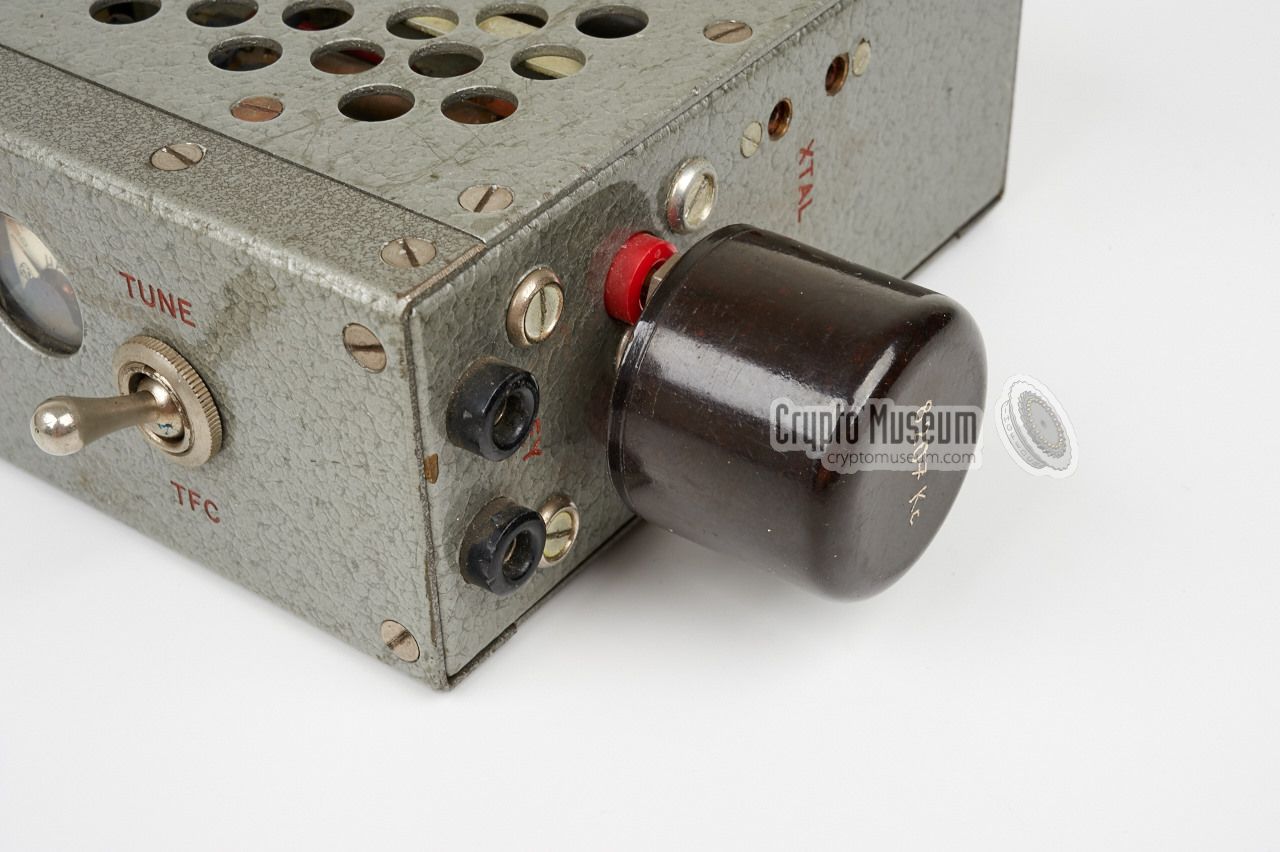
The transmitter measures only 29 x 14 x 5.5 cm and came with a
matching power supply unit (PSU) of similar size (which is missing here).
The transmission frequency is determined by a crystal
that is inserted into a socket
at the right side. Also connected at the right side is a
standard manual morse key,
such as the one shown here, or an automatic key like
Pivoňka.
The image on the right shows the Kongo 50W transmitter with a set of crystals
and a small manual morse key. The cable is for connection to the PSU.
It has a 8-pin Jones plug at the end.
|
|
|
The Kongo 50W transmitter was usually supplied as part of a complete
(spy) radio station,
that consisted of the transmitter, a power supply unit
(PSU), a suitable short-wave receiver, a set of crystals, a morse key
or an automatic keyer, frequency tables and coding material (cryto).
In order to obtains the best possible secrecy, the unbreakable
One-Time Pad (OTP) was commonly used.
|
The image on the right shows a typical Kongo 50W transmitter
(without its power supply unit) together with the complementary
Zenith Royal 1000 receiver
that was obtained in the free West.
The Zenith receiver offered a good alternative to the purpose built
spy radio receivers of the era. It was one of the first commercially
available short-wave receivers that was fully built with transistors,
and it offered a good performance. As the scale is not accurate enough
for narrow-band reception, it was commonly 'calibrated' by tuning it
to the transmitter's crystal frequency.
|
|
|
Note that the Zenith 1000-D receiver is not directly
capable of receiving CW signals – it's an AM receiver – as it
lacks a Beat Frequency Oscillator (BFO). This means that the central
station had to transmit a tone-modulated AM signal (A2), or that the
Zenith 1000D used the local oscillator of the Kongo
transmitter as an artificial BFO.
In that case, the signal from the oscillator would mix with the received
signal and produce an audible tone.
It is also possible that the
Zenith 1000-D was fitted with the S-53472 BFO kit,
that was available from Zenith as an aftermarket upgrade.
The Kongo transmitter was probably built in small quantities, as the unit
does not have a project number.
Although the radio produced an output power of 50W, it was not always
suitable for long-range communication between Congo and
Czechoslovakia.
For this reason, the 300-AB set, with an output
power of 200W, was introduced a year later (1961).
At present we have no further information about this transmitter.
If you have additional details,
please contact us.
|
 |
-
The name Kongo is probably incorrect, but as this device does not have
a project number or any other kind of identification, we have choosen it
as a nickname. Kongo is the Czech name for Congo.
-
Správa 6 refers to Government Department 6: Communication Technology.
|
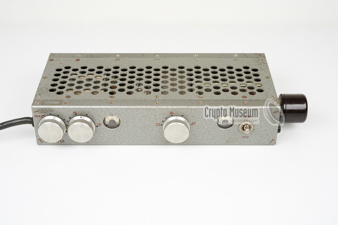
The Kongo 50W transmitter is a rather simple device with only a few
controls and connections. The black cable at the left connects the
transmitter to the PSU, which provides the LT and HT voltages. At the
right side are banana sockets for the crystal (shown below) and a morse key.
All controls are at the front. The crystal frequency can be doubled or
tripled and the Oscillator tuning knob should be set to approx. the
desired frequency, which the rightmost meter as an indicator for the
oscillator current. Antenna coupling and tuning are adjusted with the
two large knobs at the left. They should be adjusted for maximum PA current
(leftmost meter).
|
|
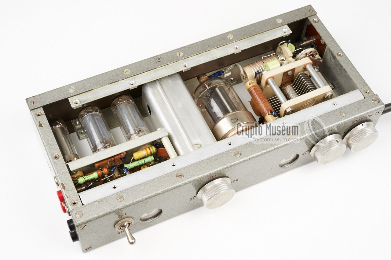
The transmitter is housed in an aluminium frame with perforated panels
at the top and bottom. These panels provide sufficient cooling for the
valves, provided that they are not obstructed. The case can be opened
by removing these two panels with no less than 16 screws at either side.
|
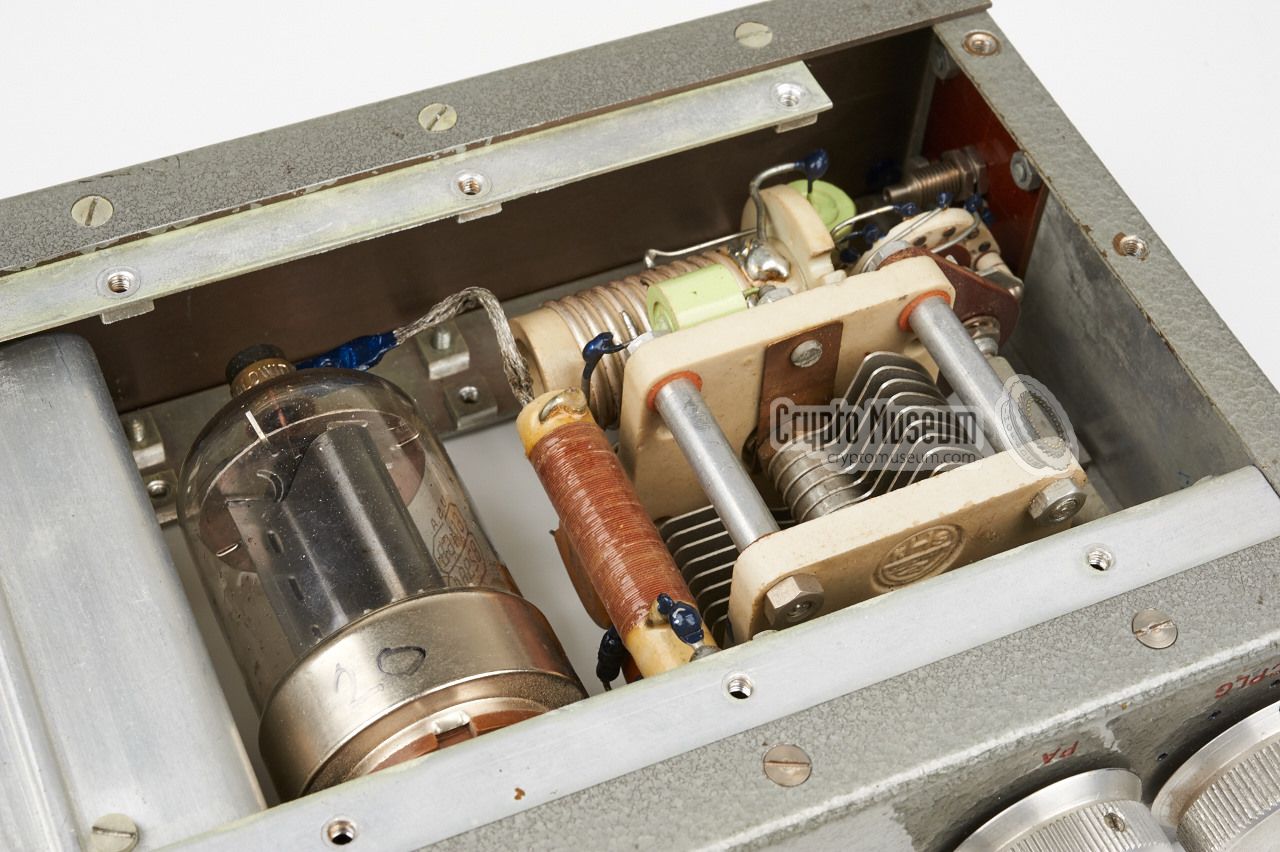
The device is well built and, despite its high age, it is still in very good
condition. At the right are three unmarked valves,
of which the rightmost one is the oscillator.
The large valve at the left is a 6146B,
made by RCA
in the US. To the left of the large valve
is a tuning capacitor, with a coil behind it.
The coil is connected to the antenna.
Unfortunately, the circuit diagram of the transmitter is not available
at the moment.
|
|
|
6146B 50W Power Amplifier (RCA, USA) 6L41 (2x) Oscillator, Frequency Doubler ? Unmarked valve, stabilizer (75 or 150V)
|
- Anonymous, Kongo 50W transmitter - THANKS!
Transmitter kindly donated by anonymous former user. July 2015.
|
|
|
|
Any links shown in red are currently unavailable.
If you like the information on this website, why not make a donation?
© Crypto Museum. Created: Tuesday 11 August 2015. Last changed: Friday, 22 September 2023 - 09:25 CET.
|
|

|
|
|