|
|
|
|
|

|
|
← 300 A CZ Cold War
The 300-AB was developed to overcome communication problems between
Congo and Czechoslovakia. The bare 300-A transmitter,
with its 20W power output, wasn't powerful enough,
and even the Kongo 50W transmitter, which was
introduced a year earlier in 1960,
was not always strong enough to reach Control.
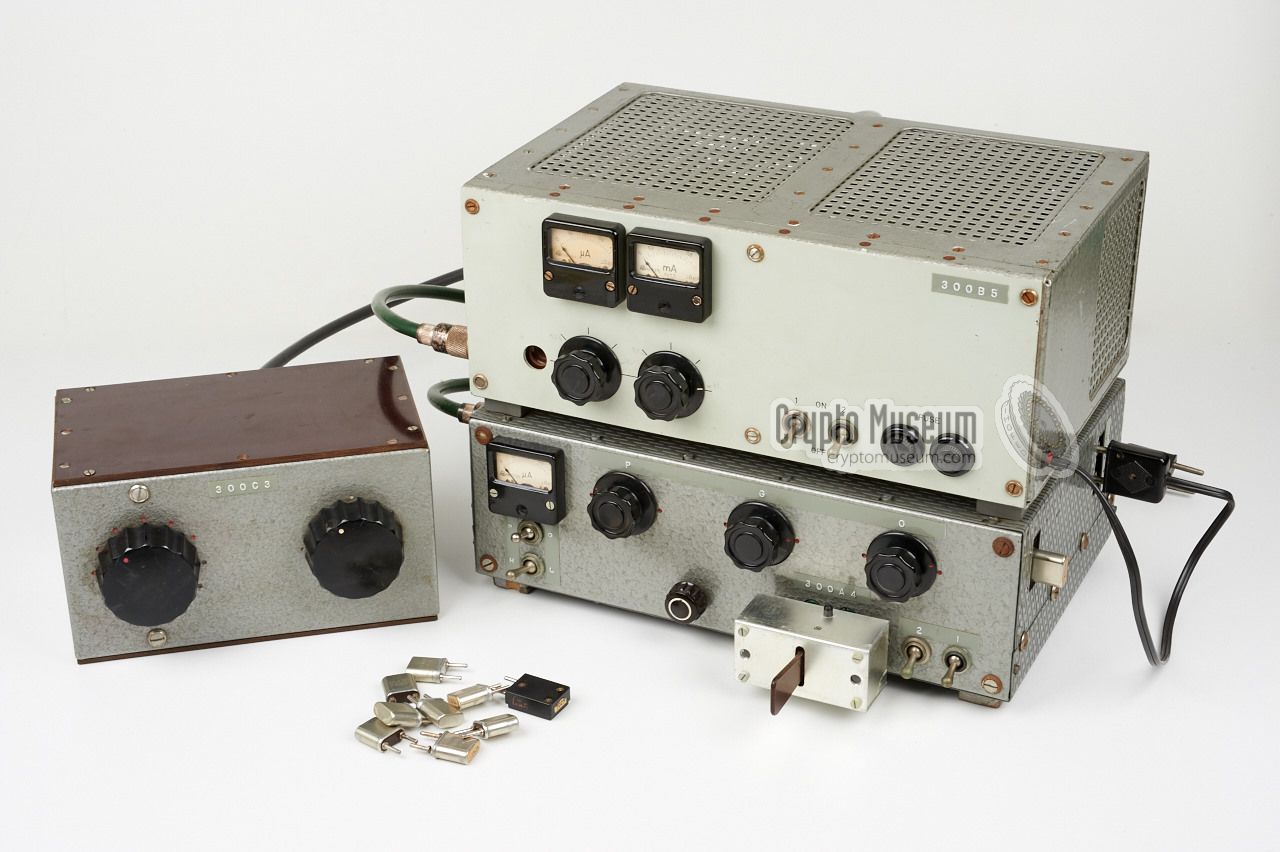
The image on the right shows the complete setup, with the transmitter
at the bottom right and the power amplifier on top of it. The device at
the left is the 300-C heavy duty antenna tuner
that came with the 300-B Power Amplifier.
|
|
|
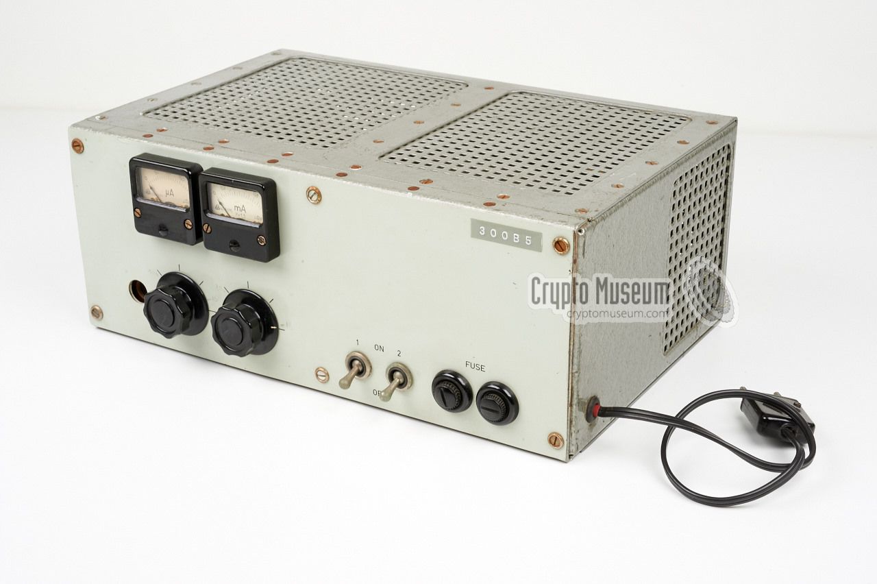
The 300B Power Amplifier is extremely heavy as it also contains a mains
power supply unit (PSU). When installed on top of the transmitter, the
mains plug should be inserted into the socket at the right side of the
transmitter. This 220V AC socket supplies the fully filtered mains voltage.
The antenna output of the Transmitter is connected to the
input at the left side of the Amplifier.
The 300-AB was probably produced in small quantities, as the units have no
project number and no engraved text on their front panels.
Instead, the text and the model number are applied by means of Dymo labels.
No documentation and/or circuit diagram is available at the moment.
The unit was used in Congo in 1961 and in
Kurdistan (a.k.a. North-Iraque) from 1965 to 1968.
|
-
Správa 6 refers to Government Department 6: Communication Technology.
|
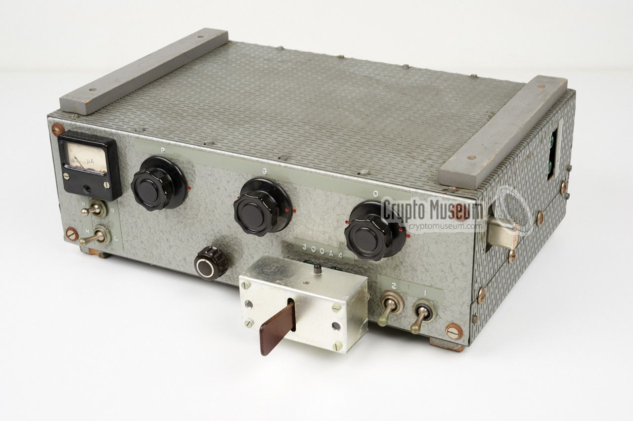
The diagram below shows the controls and connections on the 300B Power
Amplifier. The black lead at the right should be connected to the 220V
outlet on the right side of the transmitter. The output of the
transmitter goes to the input of the amplifier at the left, via a short
coaxial cable. The antenna is connected,
via the 300C antenna tuner,
to the output socket at the rear.
The amplifier should be placed on top of the transmitter, where two
wooden rigs ensure sufficient cooling for both devices. Like the transmitter,
the amplifier is switched on in two stages: (1) the LT voltage for the
filaments and, once they are heated, (2) the HT voltage.
The large knobs are for tuning the grid and plate of
the PA valve for a maximum reading of the corresponding meters.
|
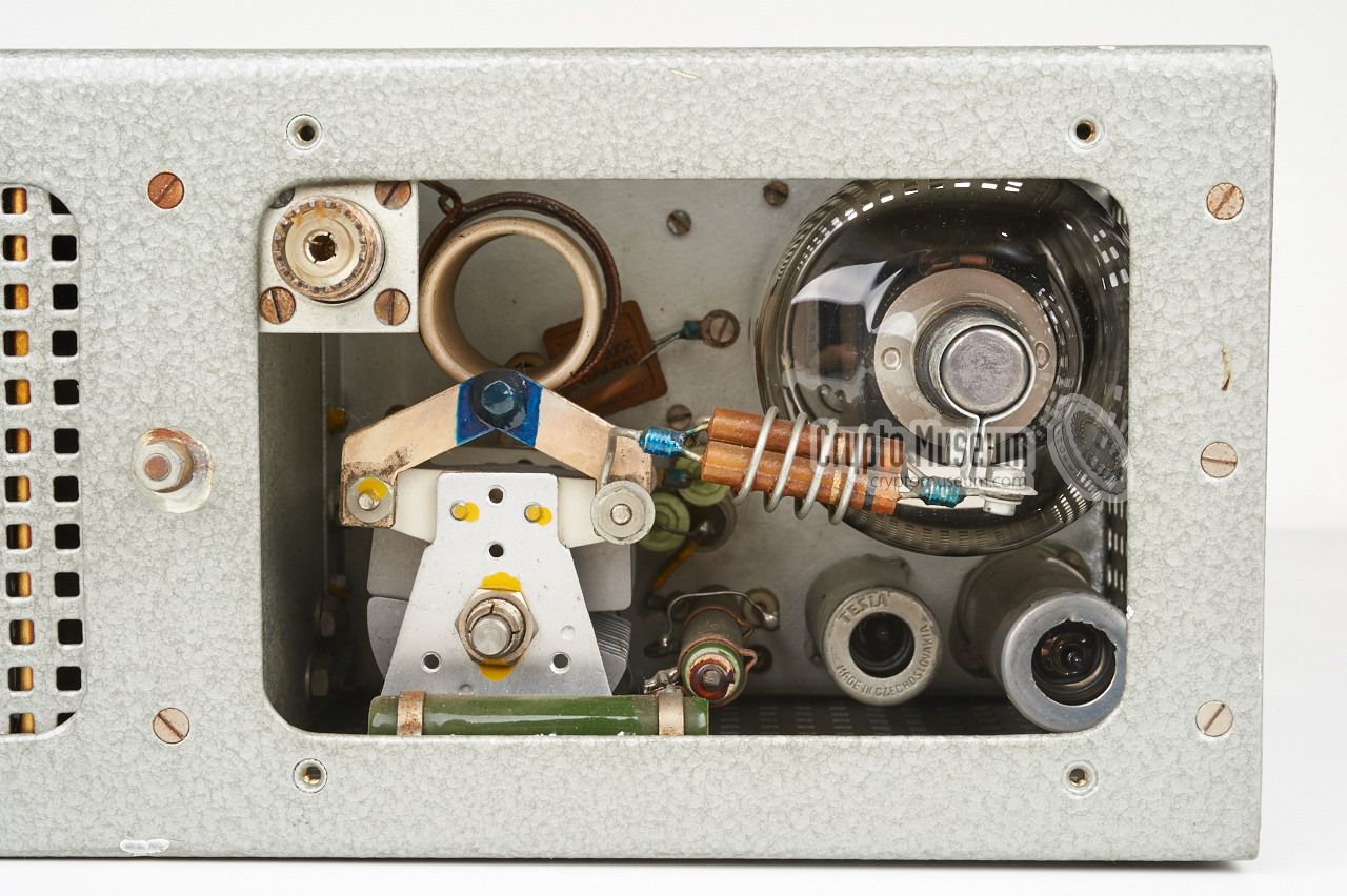
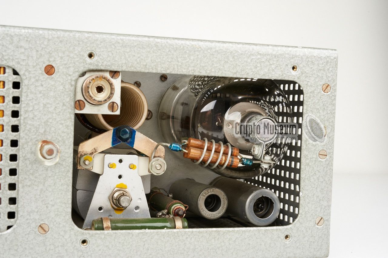
The construction of the amplifier is very simple. The right half contains
the large and heave transformer, whilst the left half contains the actual
amplifier with the QE08/200 valve at its heart. Access to the PA valve is
possible via a removable panel at the rear,
fixed with 4 screws.
The image on the right shows the PA, as seen from the rear of the device.
At the left are he tuning capacitor and the tuning coil. The large PA valve
(QE08/200) is at the top right. The PL519 output socket is at the top left.
|
|
|
QE08/200 200 Power Amplifier
|
300-A4 Transmitter 20W 300-B5 Power Amplifier 200W 300-C3 Antenna tuner for 300-B
|
|
The 300 A and the 300 AB were used in the following countries:
|
Angola 1961 (300A) Congo 1961 (300AB) Kurdistan 1965-1968 (300AB)
|
- Anonymous, 300-AB transmitter and amplifier - THANKS!
Devices kindly donated by anonymous former user. July 2015.
|
|
|
|
Any links shown in red are currently unavailable.
If you like the information on this website, why not make a donation?
© Crypto Museum. Created: Wednesday 19 August 2015. Last changed: Wednesday, 28 February 2018 - 22:43 CET.
|
 |

|
|
|