|
← PAN-1000
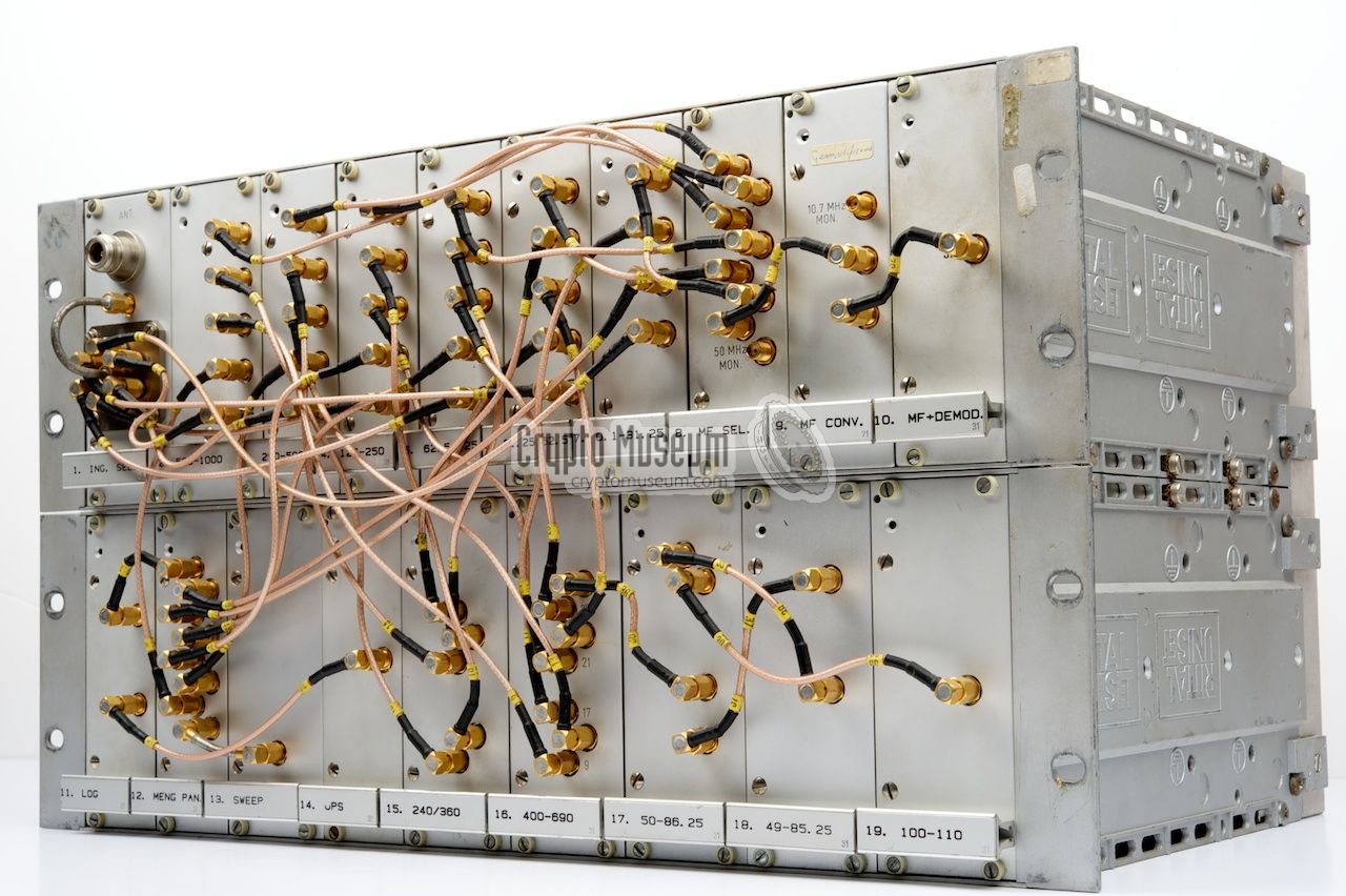
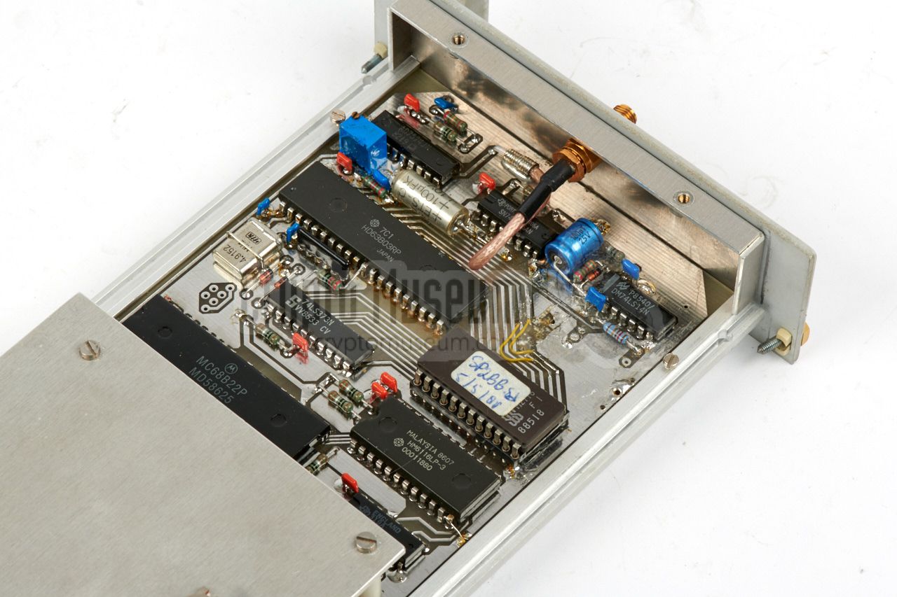
Plug-in units (modules)
PAN-1000
was a high-end intercept receiver in a 19"
rackmount case, designed and built in the early 1980s by the
Dutch Radar Laboratory (NRP),
for use by the Dutch Radio Monitoring Service.
This page provides detailed information and images of each of the
plug-in units, or modules of the main unit of the
PAN-1000.
The the list below to jump straight to the desired section.
|
UNDER CONSTRUCTION — This page is under construction and
currently acts as a placeholder for future descriptions and information
about the individual modules of the PAN-1000. The page is far from complete,
but additional information will be added in due course.
Photographs are already available.
|
The table below lists all modules of the PAN-1000 system.
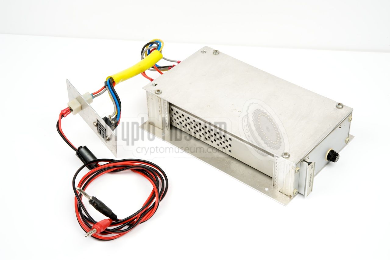
Note that only modules 1—19 are part of the main unit.
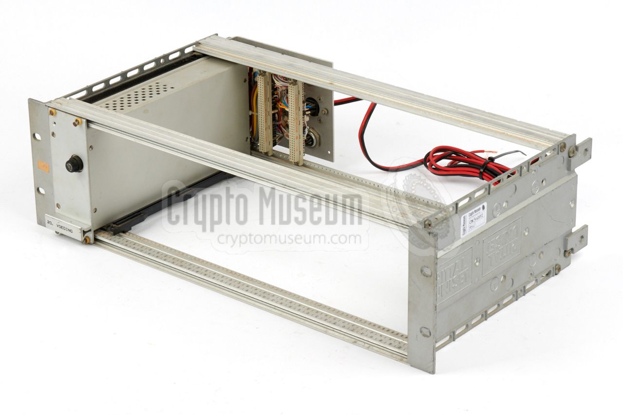
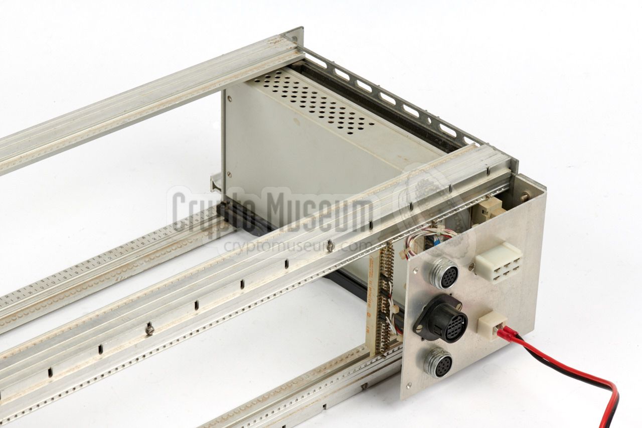
Module 20 is the power supply unit (PSU) and is housed in
a separate rack. The other modules are the peripherals.
Each module is described in more detail further down this page.
The corresponding PCB numbers are displayed in grey in the
title of each section.
|
|
When examining the individual modules of the PAN-1000, you may want to
use the block diagram below as a guide. Click any of the items in the block
diagram to jump straight to the relevant section.
For a detailed description, please refer to the
main PAN-1000 page.
|
The input selector is located at the far left of the upper rack.
It connects the antenna to one of the six
RF converters to its right (modules 2-7). It consists of a high quality
6-position RADIALL coaxial selectors, and suitable electronics
to select each of the six channels.
It also contains a 40dB attentuator that can be inserted
between the antenna and the relay by means of two RADIALL
coaxial relays.
|
|
|
 |
|
2. Converter 500-1000 MHz
84271 84280 84240
|
|
|
|
|
3. Converter 250-500 MHz
83113 84470 84280
|
|
|
|
|
4. Converter 125-250 MHz
83113 84470 84280
|
|
|
|
|
5. Converter 62.5-125 MHz
83113
|
|
|
|
|
6. Converter 31.25-62.5 MHz
83113
|
|
|
|
|
7. Converter 0.1-31.25 MHz
82452
|
|
|
|
|
8. MF Selector Unit (50 MHz)
83062
|
|
|
|
|
10. IF Amplifier and Demodulator
82055
|
|
|
|
This module takes the 10.7 MHz signal from the 50 MHz IF stage (module 9)
and splits it into two separate branches: one for the FM demodulators and
one for AM and SSB demodulators.
|
The FM branch – built around a CA3089 –
is further split into a wideband (WBMF) path and a narrowband (NBFM)
path, with the WMFM section delivering the signal for a pilot tone
detector. When a stereo signal is sensed, the letter 'S' will be shown
on the display.
...
|
|
|
|
|
11. Logarithmic Amplifier
83073
|
|
|
|
|
12. Mixer Panorama Display
83053
|
|
|
|
|
13. Sweep Synthesizer
82432 82442
|
|
|
|
|
14. Microprocessor µPS
83291
|
|
|
|
|
15. 240-360 MHz Synthesizer
82262
|
|
|
|
|
16. 400-690 MHz Synthesizer
82193 82183
|
|
|
|
|
17. 50-86.25 MHz Synthesizer
82322 82323
|
|
|
|
|
18. 49-85.25 MHz Synthesizer
82332 82323
|
|
|
|
|
19. 100-110 MHz Synthesizer
82352 82323
|
|
|
|
|
20. DC-DC Converter (PSU)
83123
|
|
|
|