|
|
|
|
|

|
|
← USA Phone Voice NSA
Digital voice encryption with OTP
- not in collection
SIGSALY was a digital
speech encryption system,
developed by
Bell Telephone Laboratories (BTL) 1
in the US in 1941/1942, and built by
Western Electric in New York (US) in 1943.
The system went into service in April 1943, just two months before the
invasion of Italy, and was used until at least 1946.
SIGSALY was used heavily during WWII, in particular for confidential
talks between British Prime Minister Winston Churchill
and US President Roosevelt.
The system used the highly-secure One-Time Pad (OTP) encryption
and is known under various names,
including The Green Hornet.
|
SIGSALY featured a number of
innovative digital communications concepts,
including the first transmission of pulse-code modulation (PCM). 2
SIGSALY was completely built with vacuum tubes (valves). A single
system consisted of more than 30 full-height 19"
racks, plus 4 synchronisable turntables.
It weighted 50,000 kg,
consumed 30 kW of power, and had special air conditioning requirements.
A single SIGSALY terminal had a price tage of US$ 1 million in 1943.
In total, 12 SIGSALY terminals were set up around the world, the
first of which was installed at the Pentagon.
|
|
|
|
The second one was installed in London in a basement of
Selfridges department store on Oxford Street. Another one was installed
on a ship that followed General Douglas MacArthur during his South Pacific
campaigns.
The systems were installed and maintained by special vetted members of the
805th Signal Service Company of the US Army Signal Corps.
Between 1943 and 1946, the 12 SIGSALY terminals conveyed more than
3000 high-level telephone conversations worldwide.
|
SIGSALY provided a full-duplex voice link via narrow-band
HF radio channels in the Short Wave (SW) radio bands. Each half of the link
used 12 individual data channels, or carriers, through which the
data was sent by means of digital
6-level Multiple Frequency-Shift Keying (MFSK).
The human voice was analysed just 50 times per second (at 20 ms intervals),
broken down into its characteristic parts,
and then coded and sent across the atlantic.
At the receiving end, the data was decoded and used to reconstruct,
or synthesize, an approximation of the original voice.
|
|
|
This resulted in a low data rate (comparable to 1500 baud today)
but made it very difficult to recognise the person at the other end.
Ultimately, this technology evolved into more advanced speech-coding
techniques, such as LPC-10,
CELP and MRELP,
in equipment like the STU-I.
Once the system was ready, the BTL developers spent the rest of the
war working on SIGSALY's successor, known as Junior X or AN/GSQ-3,
that occupied 'just' six 19" racks and could be fitted inside a movable van.
Unfortunately, it was not completed in time to see any active service [9].
After the war, SIGSALY was taken out of service as part of the demobilisation
process and most of it was destroyed, including some of its documentation.
Rumour hast it that the large racks were dumped into the sea
after SIGSALY had been decommissioned in 1946.
|
 |
-
Bell is also known as AT&T Bell Laboratories,
Bell Telephone Laboratories (BTL),
Bell Labs and just Bell. It is currently owned by the Finnish company
Nokia and is known as Nokia Bell Labs.
➤ More
-
In this context, the term Pulse-Code Modulation (PCM) is used to describe
the process of converting analogue signals into time-related numerical values,
also known as sampling or quantizing. ➤ More
|
|
SIGSALY used an unbreakable encryption scheme that was based on the
so-called One-Time Pad. The principle of this scheme
is that the human voice is first digitized and then mixed with
an element from a previously generated random key-stream.
When correctly applied, this system is unbreakable. The downside is that
both sides need to have sufficient supply of key material.
|
With SIGSALY this was solved by recording the random key stream onto
phonogram records or discs. Only two copies of the records
were made, and one copy was sent to each end of the link by special courier.
As each record could only hold 12 minutes of key material,
a large quantity of key discs had to be distributed, especially if the
system was used for very long conversations.
In addition to the key distribution problem, there was the problem of
synchronisation. The fact that digitally sampled and coded data was
sent over fading narrowband Short Wave (SW) radio channels,
implied the use of high-precision frequency standards at both ends
of the link, which had to remain synchronised during the
conversation, even if the radio signal was lost temporarily.
For the same reason, the turntables also had to be very accurate
and very stable.
|
|
|
As each record could only hold 12 minutes of key material,
two coupled turntables were used, allowing the next disc to
be cued up whilst the current one was playing. The image above
shows two synchronised turntables in an early SIGSALY setup.
As SIGSALY was a full duplex system, four turntables were present
at each terminal: two for the transmitter and two for the receiver.
Initially vinyl records were used in 1943. They were identified
by the codename SIGGRUV. This was later changed to acetate-coated
aluminium records, which were identified by the codename SIGJINGS.
In today's terminology, the SIGGRUV and SIGJINGS records would
probably be called OTP records or One-Time Records (OTR).
Note that the records were destroyed at both sides immediately
after use, so that a malicious party would never be able
to decipher any part of the secret conversation.
➤ Technical description
|
|
The first SIGSALY terminal to be completed at the Western Electric
facilities in New York City, was installed in Washington at the Pentagon,
the new headquarters of the US Department of Defense that had just been
dedicated in January 1943.
The White House had briefly been considered as a possible location, but the
installation was simply too large to be fitted anywhere in the building.
|
Instead, it was installed at the Pentagon and was connected
to the White House via an extension line.
After installation by BTL and WE personnel, maintenance
was taken over by the 805th Signal Service Company of the US Army Signal
Corps.
All personnel of the 805th was hand-picked and was trained
by BTL staff in New York City, in a special school that had been
established for the occasion. In 1944 both the 805th
and the school were moved to the Pentagon in Washington. By that
time, 193 officers and men had been trained on the use of SIGSALY,
and more were to follow.
|
|
|
The 805th would eventually consist of 356 people: 81 officers
and 275 men, who were divided over twelve detachments; one for
each SIGSALY terminal. A single detachment consisted of 5 officers
and 10 enlisted men, and was expected to operate the terminal
on a 24-hour basis [6].
|
|
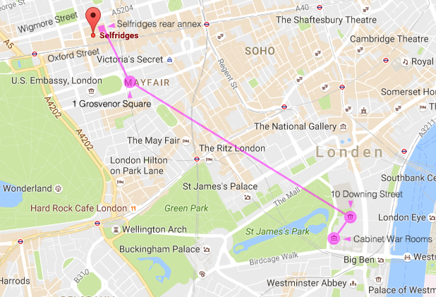
In the UK, the SIGSALY terminal was placed in the SWOD basement 1 of
the Selfridges department store on Oxford Street (London), 60 metres below
street level. The first conference took place on 15 July 1943, and the British
Prime Minister – Winston Churchill – was one of its many users [4].
|
The image on the right shows the main building of Selfridges department
store on Oxford Street in 1929, ten years before the outbreak of
World War II. At the time, Somerset Street ran directly behind the main
Selfridges building. At the other side of Somerset Street was an
annex building of Selfridges, known as the SWOD, named after the four
roads that enclosed it: Somerset, Wigmore, Orchard and Duke (the latter
three still exist).
Below the SWOD annex was a basement, known as the sub, and below
that a sub-sub basement that descends 60 metres below street level [4].
|
|
|
In 1942, after the US had entered WWII, the dry-sub-sub SWOD basement
was used by the United States Army, as the site was safe from bombing.
Here they installed one of the few secure telex lines and in April 1943
also the SIGSALY terminal, which was inaugurated on 15 July of that year.
The discussions between the two nations were probably about the Allied Invasion
of Sicily earlier that week 2 and the fortcoming invasion of Italy
that was about to take place a few months later.
The map above shows that Selfridges' basement was very close to the US
Embassy. 3 Even today there are persistent rumours of a tunnel between
the two locations [2].
Initially, SIGSALY users had to come to Selfridges for a
secure conversation with the US president, but the terminal was later
connected via extension lines to the US Embassy on 1 Grosvenor Square,
and to the offices of the British Prime Minister Winston Churchill
at 10 Downing Street and the Cabinet War Rooms. Churchill wanted
to be able to contact the US President any time of the day or night
if necessary.
|
|
-
SWOD is the abbreviation of Somerset, Wigmore, Orchard and Duke; the four
streets that once enclosed the rear building of Selfridges department store,
under which the sub-sub basement is located. ➤ Wikipedia
Somerset Street no longer exists and has been 'swallowed up' by the expanded
Selfridges store, whilst a new road, Edwards Mews, has since been
established further north, parallel to Wigmore Street.
The SWOD building is now embedded in the main store building.
-
The Allied Invasion of Sicily took place on 9/10 July 1943 and ended on
17 August [14]. It was followed by the Allied Invasion of mainland Italy
on 3 September 1943 [15].
➤ Wikipedia
-
Between 1938 and 1960 the US Embassy was located at 1 Grosvenor Square,
opposite the later US Embassy building at 24 Grosvenor Square.
In 2017 the US Embassy was relocated to the Nine Elms area [5].
|
|
Because of the size of a SIGSALY terminal, the system was generally not
located at the office where it was needed, but rather in a larger facility
somewhere nearby. In such cases, the offices were connected to the SIGSALY
terminal via special protected extension lines, known as OPEPS.
|
OPEPS [17] is short for Off-Premises Extension Privacy System.
In Washington, two OPEPS lines were installed from the Pentagon to the
White House and to the Navy Department building on Constitution Avenue.
London even had three such extensions: one to the US Embassy, one to the
Prime Minister's house at 10 Downing Street, and the third one
to the Cabinet War Rooms.
As these extension lines carried high-level ultra secret traffic,
they had to be protected against tapping in the best possible
ways, which was done by means of a variety of safety measures.
|
|
|
The cables between SIGSALY and its extensions
were piped, and were protected by gas pressure and microswitches.
Any tampering would cause the gas pressure
to drop and raise an alarm. In addition, a strong noise source was
superimposed on the twisted telephone wire pairs by means of
a bridge transformer. In normal operation, the signals on the two
wires would balance out.
|
As soon as the wires were tapped, even inside
the building, this would cause an unbalance on the line
and set off the alarm immediately.
At the same time the user would hear a strong noise through
the handset, indicating an unsafe line.
The OPEPS extension to the SIGSALY terminal should not be
confused with the UK's Frequency Changer,
commonly called scrambler phone by Churchill,
that connected the various locations of the War Department in London
during the war. Although the two phones look similar and served
similar purposes, the scrambler was not secure.
|
|
|
It was based on the inversion of the voice frequency spectrum
and was merely used as protection against an occasional eavesdropper –
such as an operator in a telephone exchange – rather than against
a professional interceptor. It was therefore called a privacy set
rather than a secrecy set.
➤ More about the UK's scrambler phone
|
|
At the start of WWII, the US Military relied on Western Electric's
A-3 Voice Scrambler for its high-level sensitive
communications.
Voice Scramblers were used by both sides during the war.
It was known however, that they were
by no means safe, and each party is known to have intercepted and broken
the other party's communications 1 with simple means like an ordinary oscilloscope.
|
The problem was recognised by Bell Telephone Laboratories (BTL)
as early as October 1940, where it was decided to start the development
of a high-level unbreakable transatlantic voice telephony system
under the name Project X.
At Bell, the research was carried out under the direction of
A.B. Clark 2 by two teams: one to do the basic research and the
other to handle the practical problems of design, construction
and instruction. The basic research was handled by the
Transmission Research group under R.C. Mathes, which included earlier
work by Eugene Peterson and Homer Dudley on the Vocoder [10].
|
|
|
Dudley's Vocoder, named Voder 3 , had been demonstrated by BTL
at the New York World's Fair in 1939 and proved that human voice
could be synthesized by immitating the effects of the human
vocal tract.
The Vocoder offered a compression ratio of 10:1 and delivered
a digital signal in the telegraph range that could be transmitted
over short-wave (SW) radio channels. Furthermore,
it allowed digital encryption with a system that was
similar to the one developed by Gilbert Vernam.
|
But before a completely secure transatlantic telephone system would
see the light of day, a large number of technical and mathematical
problems had to be solved. After a lot of testing and experimenting,
it was decided to divide the audio spectrum (150 Hz - 2950 Hz)
into 10 spectral bands or channels, each of which was
digitized or quantized into six discrete values.
In the process of developing the system and solving its problems,
many new inventions were made and
many (secret) patents were filed,
some of which were not disclosed until 35 years later.
|
|
|
By late 1941, the designs of the individual parts were more or less
ready and breadboard testing had been carried out. The next stage
was to build up a prototype, which was done by the research group
under A. M. Curtis. As the individual parts were finished, the
complete system was assembled on the 12th floor of the Graybar-Varick
building in New York City (shown below).
|
The actual manufacturing of the production machines was carried
out by Western Electric (WE). As part of the process, BTL engineers
converted much of the original design into standard WE parts that
were readily available.
Although this conversion added to the overall size of
the system, it significantly reduced the manufacturing time.
The machines were built at WE's vacuum tube plant on Hudson Street
in New York City, which was conveniently close to West Street
and the Graybar-Varick building, which is shown in the image
on the right. On the 12th floor the first X System
was assembled in 1942.
|
|
|
The X System was made up of 12 parallel data channels, 10 for the
spectrum data and 2 for the pitch, with were nearly identical,
except for their position in the FSK arrangement. In March 1942,
one complete channel was ready for review. It was tested with an
artificial fader that simulated the fading of transatlantic radio.
After successfully completing the tests, production of the other
channels was started in April 1942.
The experimental model was completed by late August 1942.
|
In November of that year the system was first tested over transatlantic
radio, against a set of synthetic signals from a generator that
had previously been sent to England. This allowed the system to
be fine-tuned and improved.
The prototype had meanwhile been nicknamed The Green Hornet,
after a popular radio show 4 of the 1930s with the same name.
The show's tune resembled the buzzing sound that would be heard
by someone eavesdropping on the system's coded signals.
It was also heard by the exchange personnel that had to
patch the lines.
|
|
|
Up to this point, all development work had been carried out on
the initiative of BTL, although the National Defense Research Committee
(NDRC) and the Signal Corps were aware of the work and had
expressed an interest in the program as early as 1942.
Around the time of completion of the experimental model, the
Signal Corps decided to sponsor the building of several terminals,
which started in September 1942. From this moment onwards,
the project was codenamed SIGSALY.
|
Once the individual parts had been completed and tested at Western
Electric, they were sent to Room L30 at West Street, the former
sound movie laboratory, where they were assembled
into a complete system. The first system was completed
on 1 April 1943, and a second one shortly thereafter,
allowing the first real test.
By the end of April 1943, just two months before the invasion of
Italy [15], the first terminals were installed in
Washington (Pentagon), London and North Africa.
In June/July 1943 more terminals followed for the
remainder of the war theatre.
|
|
|
SIGSALY was officially inaugurated on 15 July 1943, shortly
after the Invasion of Sicily [14]. The photograph above was
taken at the Pentagon terminal on that day. Present at the meeting
were Lt. Gen. T. McNarney, deputy chief of staff USA (sitting at
the head of the table at the right), Dr. O. E. Buckly, president
of BTL (at the head of the table on the left) and Lt. Gen.
Brehon Somervell, commanding general, operating the phone at
the right, whilst the others listen on headsets.
At the London end, the conference was attended by Lt. Gen.
J.L. Devers, US commanding general of the European Theatre
of Operations, Maj. Gen. I.H. Edwards, US chief of staff
of the European Theatre of Operations, and others.
As part of the inauguration, Dr. Oliver Buckley, the president of BTL,
held a brief speech for the participants, in which he predicted
far-reaching effects.
|
|
-
In the fall of 1941, the Deutsche Reichspost, tasked with handling
telephone and telegraphic traffic, had broken the American
A-3 Voice Scrambler, that was based on 1920s technology [6].
-
A. B. Clark would later become research leader at the NSA.
-
VODER was the abbreviation of Voice Operating Demonstrator.
-
The Green Hornet was a fictional crime-fighter on US radio in the
1930s and in films from the 1940s onwards. It's tune resembled
the buzzing sound made by SIGSALY on the radio channel.
➤ Wikipedia
|
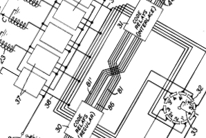
A complete SIGSALY terminal consisted of more than 30 full-height
19" racks. Approximately half of these racks were used for the
receiver, whilst the other half contained the transmitting parts.
The diagram below shows the receiving half of a SIGSALY terminal,
with part of the transmitting side visible at the left. At the
right are the four turntables that provide the random KEY streams.
|
The simplified block diagram below roughly shows how SIGSALY works.
At the left is the analyzer that converts the analogue speech into a digital
signal that is encrypted and modulated onto the transmitter.
The encryption key is produced by a one-time key phonogram disc on a
turntable. A national timing standard (broadcasting on the LW band)
is used to calibrate the internal timings.
At the receiving end, the internal timings are calibrated by the same national
timing standard. After demodulating the incoming signal, it is decrypted and
fed to a synthesizer that converts it to audible analogue speech again.
In reality, the system had two turntables at either side, in order to
allow a new OTP key record being cued up during conversations
longer than 12 minutes.
|
A vocoder is a compression device for human speech, based on the
principle that the properties of speech vary relatively slowly
due to the way the sound is generated in the vocal tract.
The frequency spectrum (150 Hz - 2950 Hz) is first divided
into 10 nearly equal bands, of which the amplitude is measured by means
of a linear rectifier and smoothed by a 25 Hz low-pass filter.
A separate system is used to determine whether the sound is voiced
(e.g. a, e, o, z) or unvoiced (e.g. s, f, k).
If the sound is voiced, its pitch or fundamental frequency
is determined. Like the amplitude, this information varies slowly and
can be limited by a low-pass filter to 25 Hz. For technical reasons, that
will be explained later, this information was sent in 2 separate channels.
This results in 12 low-frequency data channels that are sent to the
receiving terminal, where they are used to reconstruct (synthesize)
the original speech again.
If the original sound was unvoiced, the synthesizer generates white noise.
If the original sound was voiced, it generates a source of harmonics
of the fundamental frequency, that is used as the input to a series
of bandpass filters, similar to the ones used for analysis.
The output of each bandpass filter is then amplitude modulated with the
value from the corresponding data channel (1-10). After filtering
the output of each filter once more, the signals are finally
combined to produced the reconstructed speech.
|
In the above block diagram, the 12 data channels, identified by the
red dashed arrows, contain analogue information, which can not be sent
over a narrow band radio channel, and can not be encrypted easily.
This is solved by converting the information into a finite number of
steps. This process is known as quantization. For SIGSALY the data
was converted into 6 non-linear steps.
The example above shows how this works. The original (analogue) signal
is represented by the black line. This signal is sampled at
fixed intervals into one out of six possible levels, represented by
the red line. This way, each of the 10 frequency/amplitude signals
is quantized separately.
At BTL, quantization was known as STEPPING and the
sampling circuit itself was called a STEPPER.
In today's terminology, it is known as
companded digital pulse-code modulation (PCM)
[17].
Note that in today's terminology, a more appropriate expression to
describe the method of digitizing the individual parameters of
speech, would be parametric coding or vocoding,
whereas PCM is commonly used to describe direct sampling of the raw
(human) sound.
|
Sending the pitch information (i.e. the fundamental frequency of the
human voice) is slighly more complex. Early experiments at BTL had
shown that quantizing the pitch frequency to 6 discrete levels was not
sufficient and that 30 steps or more were needed for a good reproduction
of the original pitch. This was solved by using two 6-level channels
for transmission of the pitch.
The first channel carries the pitch information quantized to the
nearest 6-level value. This value is then subtracted from the original
pitch signal in order to obtain the error, or delta (Δ).
This Δ-value is always less than 1/5th of the original value.
After multiplying it by five, it is quantized by a similar circuit
into 6 discrete levels and sent in the second channel.
This way, the pitch data is quantized in 36 levels (6 x 6), which
is more than the minimum of 30 levels that were required.
The above block diagram shows how the two pitch values were obtained.
They were each sent in a separate 6-level channel. The sampling interval
had to be much longer than the typical 2-3 ms path delay differences
caused by selective fading on a transatlantic radio link.
After trying many combinations, a 6-level arrangement with a
20 ms (50 Hz) sampling rate appeared to work best.
The technique of sending the pitch information as two separate
values (coarse and fine) is also known as
two-step vernier quantization or residual quantization.
It was first used on SIGSALY.
|
In a digital system like SIGSALY, timing is paramount.
For correct operation it is mandatory that the systems at both ends
are properly synchronised and stay synchronised for the duration of the
conversation, even over a fading medium, like a (14,000+ km)
transatlantic short-wave radio
link which sometimes drops-out completely.
Although this initially seemed like a difficult-to-solve
problem, it turned out to be relatively simple, mainly due to the choice
of system parameters, such as the low sampling rate of 20 ms (50 Hz).
All that was needed at both ends, was a stable high-precision frequency
standard or reference oscillator. Once both systems were 'in-sync',
they would stay synchronised for several hours without any considerable drift.
Short-term drifting was never large enough to cause trouble with the sampling
rate, and long-term drifting could easily be compensated for.
A BTL engineer 1 even developed a system for
Automatic Frequency Correction (AFC) to correct for frequency shifts which
might occur in carrier radio systems. This greatly improved the FSK
transmission system.
In practice, the synchronisation never posed any serious problems.
Although the signal was sometimes lost completely for considerable
periods, due to the atmospheric conditions of the HF radio channel,
the system would still operate correctly once transmission was restored.
The only part of the system for which timing was really critical,
was the keyer
with its phonogram records.
|
|
-
Automatic Frequency Correction (AFC) was added by Harold L. Barney.
|
For encryption of the twelve 6-level signals, a mixing system is used
in which a 6-level signal from a random noise source is added to
the original quantized 6-level speech data, by means of modulo-6 addition,
similar to the way in which the Vernam Cipher
works for 2-level digital telegraphy signals
in an OTT cipher system.
At BTL, this technique was known as REENTRY.
The simplified block diagram above shows how the data from the KEY
stream is added to the data from the digitized speech channel. Both
values are in the range 0-5. If the sum of the two values is higher
than 5, it gets 'wrapped around' by the REENTRY circuit, so that the
result remains in the 0-5 range.
The diagram below illustrates how this works
for SIGSALY's 6-level numerical data.
The diagram at the top shows the original speech signal that is quantized
into 6 discrete levels, as shown by the red line. The middle diagram
shows the key that will be added to the original signal. The key is
generated by a noise source and is recorded onto a disc. When playing back
the disc, its signal is sampled at the same intervals and its quantized
6-level values (the blue line) are added to those of the original signal
by means of a mathematical modulo-6 addition (at the time known as
re-entry).
The result is represented by the green line in the diagram at the bottom.
Modulo-6 addition can best be explained by following the hands of
a clock, as illustrated by the diagram above. In this example, the
initial value is 4 and the KEY value is 3. Adding these two values
together produces 4 + 3 = 7. Which gives us the result (output)
of 7 modulo 6 = 1. In other words: the KEY value determines
the number of steps that have to be added to the INPUT.
At the receiving end, a copy of the key disc is used to retrieve
the original data again, simply by subtracting the KEY value from the
previous result. In the above example, the input value is 1 and the
KEY value is 3, which produces the result
1 - 3 = -2, and -2 modulo 6 = 4.
In other words: the value has to be rotated 3 steps counterclockwise
in order to reproduce the original value.
|
Generation and duplication of the cryptographic KEY material was one
of the most critical parts of the entire system, as it directly
determined the security of the cipher. Each of the KEY characters,
or steps had to be completely random, and the random sequence of
characters should never be repeated. Furthermore, a separate random
character stream was needed for each of the 12 data channels.
Using the same key for all channels would have been a cryptographic
weakness.
Creating the random stream of characters was solved by using
a white noise source, symbolised in the above block diagram by a
diode. In reality, the noise generator was based on a hot cathode
gas discharge valve (tube). After amplification, the noise signal
is sampled by a so-called stepper circuit into 6 discrete levels
(0-5) similar to the amplitude sampling steppers
in the Vocoder.
After much consideration at BTL, it was decided to use phonogram
records or discs for the actual distribution of the KEY
material, as this was one of the most reliable and stable reproduction
processes as the time. Nevertheless, it required
very special precisely-driven turntables for both the production
and play-back process, in order to meet the strict system
timing requirements.
The quantized 6-level noise signal is used to control the amplitude
of a fixed-frequency tone generator as illustrated above.
This results in an Amplitude Modulated (AM) tone with
6 discrete levels. After filtering and amplification, this signal
is then recorded onto a phonogram disc.
By using 12 nearly identical key production circuits, with a
different tone for each of the 12 channels, the KEY stream for
all 12 channels is recorded simultaneously onto a single disc,
as illustrated in the block diagram above. The audio tones were
selected carefully, as they were not allowed to have any relation
between them.
This process is described in US Patent 3,373,245.
|
As each phonogram record could only hold about 12 minutes of
KEY material, several such discs were needed for a single
conversation. In order to guarantee uninterrupted operation,
two turntables were used, allowing the next disc to be 'cued up'
whilst the current one was running.
For this to work properly, both discs had to be identical and had
to be started at exactly the same position. This was solved by
creating the discs simultaneously on two electrically coupled
phonogram recorders or cutters, and placing index marks
on the discs automatically. All the operators at both sides had
to do, was to place the needle in the correct groove at the index
mark. In order to guarantee quick synchronisation after start-up,
the motors of both turntables were kept running all the time,
synchronised to the general system timing (reference oscillator).
The timing of a play-back turntable, is referenced to a
contact that is briefly engaged at each full revolution.
This producs a so-called tacho-pulse that can be used for
synchronisation.
This way, not only the rotational speed, but also the exact angle
(position) of the disc could be controlled.
Towards the end of each KEY record, a control tone
or pilot tone is recorded (with the existing key tones)
to mark the start of the other turntable.
At the beginning of the tone, an electric latching mechanism
is engaged to couple the table instantly to the motor axle on the
start of the next revolution of the table.
At the end of the tone, the second turntable is assumed to be stable
enough, and the key stream is switched to that turntable.
The first one can then be reloaded.
The simplified block diagram above shows how the rising and falling
edges of the control tones are used to start and stop the motors of
the two turntables, and to select which record is used as the source
of the key stream. The three units at the right are so-called
set-reset flip/flops.
The diagram above illustrates how a solenoid-operated
latch was used to couple the turntable to the continuously running
(synchronised) motor. The motor drives a large heavy flywheel 1 that is
kept running all the time. In the drawing, the leftmost latch is engaged,
whilst the one at the right is waiting to be activated by the control tone.
The operation of control tone-operated disc cueing and disc indexing
is described in more detail by Kingsbury Davis in
US Patent 3,024,321.
|
|
-
Note that in reality the flywheel was probably much bigger than
it is shown in the simplified drawing above.
|
|
Although the use of One-Time phonogram records with truly random keys
was the only way to guarantee absolute cipher security, they were not
very practical for testing and maintaining the machines.
Their production was very expensive and each record only lasted 12 minutes.
|
BTL Engineers therefore developed a mechanical device with many
electrical relays, that produced a pseudo random key that was good enough
for lineup and testing of the installation. This device was, of course,
never used for high-level calls.
Because of the noise it made in
operation, the device was affectionally called the 'trashing machine' [9].
Its operation is described in great detail by Oscar Myers in
US Patent 3,937,888,
that was filed in 1943 and was kept secret for more than 31 years
before it was declassified in 1975. The image on the right shows
part of it.
|
|
|
In an operational context it the trashing machine was known as the
Alternate Key, or AK. It was later assigned the official name SIGBUSE.
The AK was used for daily maintenance and for less important conversations,
but was known to be unreliable. If phonogram records were used and the
system lost its synchronisation, the call would be interrupted immediately.
When the AK failed, e.g. due to a failing relay contact, it would start
with an intermittend sound that resembled a galloping horse, which gradually
became worse as the error propagated through the system [1].
|
Transmitting a 6-level data signal was another challenge.
Amplitude Modulation (AM) was tried, but was found inadequate
as a result of selective fades that could at times be as much
as 20 dB. In order to accurately reproduce the 6-level signal,
the amplitues had to be produced with a 1% accuracy (1 dB).
The solution was to use a technology known as:
Frequency-Shift Keying (FSK).
FSK was already used successfully in digital telegraphy (telex).
As a telex character is represented by a 5-bit digital value,
each bit is represented by one of two levels: a 0 or a 1,
or in telegraphy speak: a mark and space. This means that
only two frequency positions were needed to send the state of
a single bit, hence the name two-level FSK, or just FSK [11].
To send six-level data, six frequency positions are needed,
hence the name Multiple Frequency-Shift Keying or MFSK [12].
The implementation posed many new problems for which
new filter techniques were developed.
In SIGSALY, 12 such 6-level MFSK channels had to be transmitted
to the other end. This was done by Frequency Modulating (FM)
the 6-level stepped data onto a Low Frequency (LF) carrier in
the 1000-3000 Hz range. This part was identical for all 12 channels.
The 12 FM signals were then each Amplitude Modulated (AM)
onto LF carriers with incrementing frequencies. After removing
one of the sidebands, the results were mixed and sent on a
High Frequency (HF) AM carrier.
This resulted in another first for SIGSALY: Multi-Carrier
Transmission. A good description of the modulation techniques
used for SIGSALY are provided by Robert Mathes in
US Patent 3,991,273
that was filed on 4 October 1943 and was kept secret for 33
years. It was disclosed in 1976.
|
|
British mathematician Alan Turing,
known for his work on breaking the German Enigma cipher,
the development of the Bombe codebreaking machine
and for his pioneering work on computers, was briefly involved in
SIGSALY's development.
In November 1942 he went on a two month top-level liaison mission
to the United States, to oversee their codebreaking work on
Naval Enigma.
|
In his first week he visited Benjamin deForest Bayly in New York,
with whom he discussed the security of
Telekrypton, an old Western Electric
cipher machine that Bayly was converting into a
One-Time Tape device.
Bayly's machine would later evolve into
the unbreakable Rockex.
On his trip, Turing also visited BTL where, after the initial
security clearance problems, he was allowed to see and discuss the
progress on their developments of the voice encryption system.
It required personal intervention by Field Marshal Sir John Dill and
General George C. Marshall, but utimately Turing was allowed to see
SIGSALY.
|
|
|
Turing recognized the quality and the importance
of the work that was done at BTL [16]. He was convinced about the security
of the system, but had his reservations about the fact that SIGSALY
would be operated exclusively by US personnel, which gave them the
ability to listen in 'if they so desired' [17].
Nevertheless, he gave his approval for installation and use of the device in London.
Turing's consent was a very important one, as it probably contributed
to the development of the US-British inter-relations, that were
later formalised by the signing of the British-United States
Agreement (BRUSA) in May 1943.
On his return to the UK, Turing started the development of
Delilah,
a similar system that was based on the work he had seen at BTL.
Although Delilah
was never taken into production, Turing fed some of
his ideas back to BTL for use in SIGSALY.
|
|
The name SIGSALY was not an acronym, but a cover name or codename,
starting with the letters SIG, just like in
SIGABA
and SIGTOT.
The first prototype was named The Green Hornet, after the buzzing
sound it produced on the communication channel.
The following names were used:
|
- SIGSALY
- X System
- Project X
- Ciphony I
- Green Hornet
|
|
In total 12 complete SIGSALY terminals were built and installed
around the world. The following SIGSALY locations have been confirmed
[8]:
|
- Washington (US, Pentagon)
- London (UK, Selfridges)
- Algiers
- Brisbane (Australia)
- Fort Shafter (Hawaii)
- Washington (US, for Pacific)
- Oakland (US, California)
- Paris (France, after liberation)
- Guam (maritime installation) 1 ➤
- Frankfurt (Germany, post-war)
- Berlin (Germany, post-war)
- Tokyo (Japan, post-war)
- Manilla (Philippines) 2
|
|
|
Each terminal was able to contact every other terminal, and could also
be used for relaying a conversation. There are examples of conversations
between London (UK) and Brisbane (Australia), that were relayed via
Washington (USA), as described by David Kahn in September 1984 [17].
|
-
This system was installed on a 250-ton lighter that followed
General MacArthur during his South Pacific campaigns. As an example,
the image shows a 250-ton Australian AV-2050 120ft Motor Lighter,
which might have been a candidate for the maritime installation [21].
➤ Wikipedia
-
One or more installations may have been relocated after the war.
It is also possible that the maritime installation (9) showed up
at this location. There were never more than 12 terminals in total.
|
|
The following technologies are claimed as SIGSALY 'firsts' [8]:
|
- Encrypted telephony (as opposed to voice scrambling)
- Quantized speech transmission
- Transmission with Pulse Code Modulation (PCM)
- Companded PCM
- Multiple Frequency-Shift Keying (MFSK)
- Speech bandwidth compression
- Frequency Shift Keying-Frequency Division Multiplex (FSK-FDM)
- Multilevel 'eye pattern' to adjust sampling intervals
- Two-step vernier (residual) quantization
- Multi-carrier transmission 1
|
-
In some literature, this feature is described
as Spread Spectrum transmission, which was probably correct at the
time it was invented. The term 'multi-carrier transmission'
describes it more accurately however.
|
|
Amoung others, the following people were involved in the development
of SIGSALY (ordered alphabetically by surname):
|
Badgley, Robert H. Vernier quantization Barney, Harold L. Automatic Frequency Crrection (AFC) Barstow, J. M. Vocoder manufacturing Bennett, W. R. PCM, Transmission systems Blye, P.W. Project engineer expanded project (September 1942) Busch, Aloysius J. Pseudo Random Key Generator (US Patent 3,968,454) Clark, A.B. Project leader Vocoder Research group Cole, I.E. Precision phonogram recording Curtis, A.M. Project leader Circuit Research group Davis, Kingsbury H. Key system Dow, J. L. Switching Development group Dudley, Homer W. Vocoder Edson, J. O. PCM Gannett, Danforth K. Vocoder Gray, C. R. Manufacturing at Western Electric Hartley, R.V.L. Transmission systems, Consultancy Joel, A.E. Pseudo Random Key Generator Llewellyn, F. B. PCM Lundstrom, Alexis A. Stepper, Reentry Marrison, A. C. Precision phonogram recording Mathes, Robert C. Transmission Research group, Random Noise Meacham, L.A. PCM Melhose, Alfred E. Prototype building coordination and drawings - Vernier quantization
Mitchell, D. Message coding equipment manufacturing Mohr, Milton E. Digital encoding, Quantizer (stepper) Myers, Oscar Pseudo Random Key Generator (US Patent 3,937,888) Newby, Neil D. Key system (early work) Norwine, Andrew C. Key system Nyquist, Harry Vocoder, PCM, Consultancy Olcott, E. W. Manufacturing at BTL (also at Western Electric) Peterson, Eugene PCM Potter, Ralph K. Vocoder Riesz, R. R. Vocoder, pitch extraction Schimpf, Luther G. Limiter/detector, Stepper, Reentry Shannon, Claude PCM, Reentry (modulo 6), cryptanalysis - Consultancy, Project oversight (UK)
Vaughan, Henry E. Key system (early work)
|
Most of the SIGSALY-related patents were filed in or around 1942 by
some of the people listed above,
but were not disclosed until 1976 [9]. The technologies described in the patents
are at the heart of modern communications, including the
Global System for Mobile communication (GSM).
Below is an overview of the patents that were filed in relation to SIGSALY.
The rightmost column, highlighted in red, shows how many years the patent
was kept secret, before it was officially released to the public.
Click the patent number in the first column to view the original patent.
|
| Patent | Inventor | Title | Filed 1 | Released 1 | # 2 |
|
|
| 2,151,091 | HW Dudley | Vocoder | 1935-10-30 | 1939-03-21 | 3 |
|
|
|
Patents related to Project X
|
|
|
| Patent | Inventor | Title | Filed 1 | Released 1 | # 2 |
|
|
| 3,024,321 | KH Davis, AC Norwine | Key record (Continuous recording system with indexing means) | 1944-12-29 | 1962-03-06 | 17 |
| 3,076,146 | ME Mohr | Cathode beam tube circuit having means for converting current variations to stepped waveform | 1945-12-27 | 1962-01-29 | 16 |
| 3,188,390 | ME Mohr | Signal transmission with secrecy | 1943-12-20 | 1965-06-08 | 21 |
| 3,193,626 | HL Barney | Duplicate record indexing system | 1944-12-29 | 1965-07-06 | 20 |
| 3,340,361 | RK Potter | Signaling system with cathode ray tube quantizer | 1945-07-09 | 1967-09-05 | 22 |
| 3,373,245 | ND Newby, HE Vaughan | Production of current of random variation | 1942-08-27 | 1968-03-12 | 25 |
| 3,394,314 | LG Schimpf | Circuit supplying impulses of regulated peak amplitude | 1943-07-17 | 1968-07-23 | 25 |
| 3,405,362 | RH Badgley, LG Schimpf | Space discharge tube circuit | 1943-12-20 | 1968-10-08 | 25 |
| 3,470,323 | HW Dudley | Signalling system | 1944-06-30 | 1969-09-30 | 25 |
| 3,967,066 | RC Mathes | Secret telephony | 1941-09-24 | 1976-06-29 | 35 |
| 3,967,067 | RK Potter | Secret telephony | 1941-09-24 | 1976-06-29 | 35 |
| 3,985,958 | HW Dudley | Secret telephony | 1941-12-18 | 1976-10-12 | 35 |
| 3,897,591 | AA Lundstrom, LG Schimpf | Secret transmission of intelligence | 1942-08-27 | 1975-07-29 | 33 |
| 3,912,868 | RH Badgley, RL Miller | Telephone pricacy system | 1943-07-17 | 1975-10-14 | 32 |
| 3,937,888 | O Myers | Signal transmission with secrecy | 1943-07-17 | 1975-02-10 | 31 |
| 3,991,273 | RC Mathes | Speech component coded multiplex carrier wave transmission | 1943-10-04 | 1976-11-09 | 33 |
| 3,979,558 | E Peterson | Signalling system | 1944-06-30 | 1976-09-07 | 32 |
| 3,976,839 | RL Miller | Telephone privacy system | 1944-06-30 | 1976-08-24 | 32 |
| 3,965,296 | RL Miller | Signaling system | 1944-06-30 | 1976-06-22 | 32 |
| 3,887,772 | RL Miller | Signal privacy with safety feature | 1944-06-30 | 1975-06-03 | 31 |
| 3,891,799 | AE Melhose | Code device with light responsive key generator | 1944-09-27 | 1975-06-24 | 31 |
| 3,983,326 | DK Gannett | Key pulse generator for secrecy signalling circuit | 1944-09-27 | 1976-09-28 | 32 |
| 3,968,454 | AJ Busch | Signaling circuit | 1944-09-27 | 1976-07-06 | 32 |
| 3,944,744 | DK Gannett | Matrix coding secret signalling system | 1945-05-10 | 1976-03-16 | 31 |
| 3,944,745 | DK Gannett | Secret signaling system with means for preventing key disclosure | 1945-05-10 | 1976-03-16 | 31 |
| 3,953,677 | DK Gannett | Key signaling system with multiple pulse generators | 1945-05-10 | 1976-04-27 | 31 |
| 3,953,678 | DK Gannett | Speech component key signaling system with code combinations | 1945-05-10 | 1976-04-27 | 31 |
| 3,924,074 | E Peterson | Pulse position modulation key signaling system | 1945-05-19 | 1975-12-02 | 30 |
| 3,983,327 | DK Gannett, AC Norwine | Electrical signaling | 1945-07-09 | 1976-09-28 | 31 |
| 3,934,078 | DK Gannett | Key generating system | 1946-05-01 | 1976-01-20 | 30 |
| 3,965,297 | DK Gannett | Secret communication signal generating system | 1946-05-01 | 1976-06-22 | 30 |
| 3,924,075 | DK Gannett | Two-way privacy system terminal with single key pulse generator means | 1947-03-20 | 1975-12-02 | 28 |
|
|
-
All dates are in European notation DD-MM-YYYY.
-
Number of years before the patent was declassified.
|
|
Below is a selection of video clips that are related to SIGSALY or
some of its features. Please note that Crypto Museum is in no way
affiliated with or involved in any of these video productions or its makers,
and can not accept any responsibility for the correctness of the
provided information.
|
|
|
Encryption, Episode 1 - SIGSALY: AT&T Labs
|
|
|
|
The clip below is the first episode of a series of video presentations
by AT&T. It discusses the invention of SIGSALY, the worlds first unbreakable
telephony device that was developed by Bell Telephone Labs (BTL).
At the time, BTL was a full subsidary of AT&T.
|
|
|
The Voder - Homer Dudley (Bell Labs) 1939
|
|
|
|
Voder was the first device that could produce an electronically synthesized
human voice. It was developed by Homer Dudley at Bell Telephone Laboratories
(BTL) in Murray Hill (New Jersay, USA). The video clip features the full audio
of a demonstration at the New York World's Fair in 1939.
|
|
|
VODER (1939) - Early Speech Synthesizer
|
|
|
|
Below is a short video clip that shows how VODER was operated manually
by Helen Harper to imitate the human voice. It gives a good impression
of how SIGSALY must have sounded.
|
|
AFC
|
|
Automatic Frequency Correction
Method for automatically correcting the frequency of an oscillator
in order to keep a receiver tuned to the center of a signal's carrier.
|
|
AK
|
|
Alternate Key
Electromechanically produced pseudo-random key that could be used
with SIGSALY instead of the (expensive) phonogram records. The AK
was used for testing and for low-level calls. Codenamed SIGBUSE.
➤ More
|
|
FSK
|
|
Frequency-Shift Keying
Method for transmitting a 2-level (binary) digital signal by means
of shifting the carrier frequency. In Frequency Modulation (FM) this
is done by sending the two levels as audio tones (AFSK).
➤ Wikipedia
|
|
MFSK
|
|
Multiple Frequency-Shift Keying
Similar to FSK, but suitable for multi-level digital signals.
In the case of SIGSALY, 6-level data was transmitted this way.
➤ Wikipedia
|
|
OPEPS
|
|
Off-premises extension privacy system
Secure (local) extension lines to SIGSALY, protected by means of
gas pressure on the cables, microswitches on the connection boxes,
and balanced noise on the twisted wires of the lines.
|
|
PCM
|
|
Pulse-code modulation
Digital representation of a sampled analogue signal [17].
➤ More
➤ Wikipedia
|
|
SIGBUSE
|
|
codeword
Codeword for the Alternate Key (AK), an electromechanical device
that generated a pseudo-random key stream, used for testing.
Also known as the Trashing Machine.
➤ More
|
|
SIGGRUV
|
|
codeword
Codeword for the vinyl-based phonograph records with 12 minutues
of OTP key material for SIGSALY, that were initially used.
➤ More
|
|
SIGJINGS
|
|
codeword
Codeword for the acetate-coated aluminium phonogram records
that replaced the SIGGRUVS vinyl records.
➤ More
|
|
SIGSALY
|
|
codeword
Codeword for the complete full-duplex secrecy telephony system
described on this page. Initially known as X System or Project X.
➤ Other names
|
- J.V. Boone and R.R. Peterson, Sigsaly - The Start of the Digital Revolution
NSA Website. Retrieved September 2015.
- Wikipedia, SIGSALY
Retrieved October 2016.
- Jerry Proc and contributors, SIGSALY
Retrieved November 2015.
- Wikipedia, Selfridges, Oxford Street
Retrieved October 2016.
- Wikipedia, Embassy of the United States, London
Retrieved October 2016.
- Patrick D. Weadon, Sigsaly Story
Retrieved October 2016.
- Wikipedia, Pulse-code modulation
Retrieved October 2016.
- James V. Boone, The WWII Cryptologic Heritage of the United States'
Computer and Communications Industries.
Date unknown.
Page 6 refers to an 1983 IEEE review.
- Project X - A True Secrecy System for Speech - Section 4.3 (extract)
Author: RL Miller (Section 4.3), Engineering and Science in the Bell System
Bell Telephone Laboratories, Inc. 1978. pp. 296-317. ISBN 0-932764-00-2. 1
Ralph Miller was one of the SIGSALY developers ➤ More
- Wikipedia, Vocoder
Retrieved October 2016
➤ Homer Dudley's Voder
- Wikipedia, Frequency-shift keying
Retrieved October 2016.
- Wikipedia, Multiple frequency-shift keying
Retrieved October 2016.
- Donald Mehl, Personal correspondence
Various SIGSALY images. October 2016. 2
- Wikipedia, Allied invasion of Sicily
Retrieved October 2016.
- Wikipedia, Allied invasion of Italy
Retrieved October 2016.
- Alan Turing, Report from Washington
Report on Cryptographic Machinery available at the Navy Department Washington.
28 November 1942. Crown Copyright.
- David Kahn, Cryptology and the origins of spread spectrum
IEEE Spectrum, September 1943. pp. 70-80.
- Donald E. Mehl, The Green Hornet: America's unbreakable code for secret Telephony
1997-2002. Self-published.
- The National WWII Museum, Pentagon aerial view 1943
New Orleans. Source unknown. Retrieved October 2013.
- Sydney W. Newbury, Image of Selfridges, Oxford Street, 1929
RIBA Library Photographs Collection.
Obtained via Victoria and Albert Museum.
October 2016.
- Wikipedia, 120ft Motor Lighter
Retrieved November 2016.
|
|
-
Restored by means of OCR from a scanned document by David Allen. October 2005.
-
Reproduced here by kind permission from the author.
|
|
|
|
Any links shown in red are currently unavailable.
If you like the information on this website, why not make a donation?
© Crypto Museum. Created: Sunday 30 October 2016. Last changed: Monday, 06 October 2025 - 14:41 CET.
|
|

|
|
|
| |


![One half of a SIGSALY terminal showing the receiving end. Copyright NSA, obtained via Jerry Proc [3].](img/sigsaly_complete.jpg)
![The transmitting side of a SIGSALY terminal. Photograph via Donald Mehl [13].](img/mehl_sigsaly.jpg)
![Two linked turntables. Photograph via Donald Mehl [13].](img/mehl_turntables.jpg)
![The Pentagon in January 1943 [19]](img/pentagon_1943.jpg)
![Selfridges department store in 1929. At the left, Somerset Street is just visible. [20]](img/selfridges_1929.jpg)


![Presentation of the VODER at the New York World's Fair in 1939 [10]](img/voder1.jpg)