|
|
|
|
|

|
972 MHz radio bug with subcarrier audio-masking
KOS-11 (Bulgarian: КОС-11) was a
Cold War
radio frequency (RF)
covert listening device (bug),
developed in the early 1980s in Bulgaria,
at that time a member of the Warsaw Pact.
The device is crystal-operated and works in the 950 MHz band.
It was used from 1984 onwards by the
East-German (DDR)
security service — MfS
or Stasi — for covert overhearing
of conversations in a car.
It is also known by its Stasi project number 33212
and belongs to the 3rd generation of bugs.
|
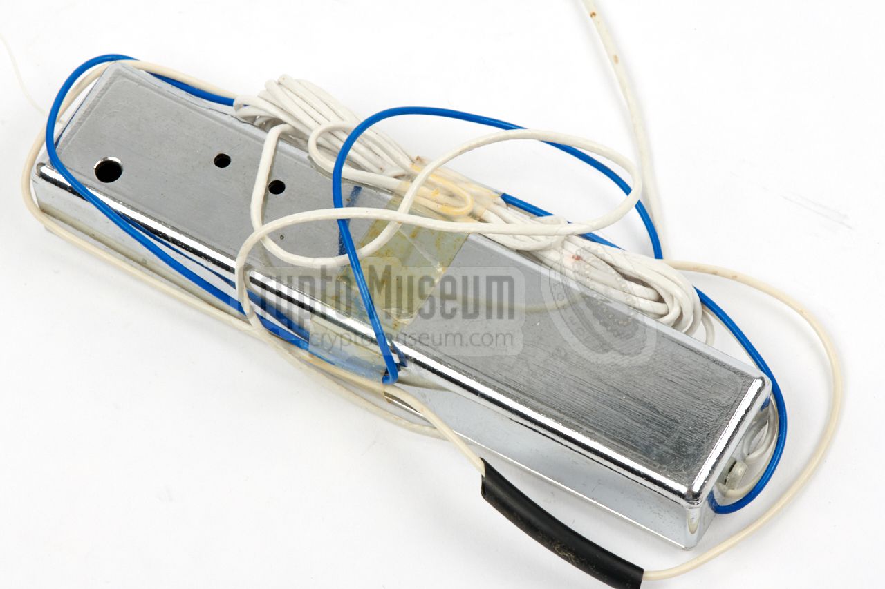
The device measures 130 x 28 x 19 mm and weighs 64 grams.
It can be powered by any DC power supply between 8 and 15V,
such as the 12V battery of a vehicle.
When it was used for overhearing a conversation inside a
(moving) car, the device was commonly hidden between the
lining and the metal roof of the car, in such a way that
the wire antenna was least obstructed.
It has a fixed thin 3 metre shielded cable,
with a Knowles BT1751 electret microphone at the end.
This allows the microphone to be installed at the optimal position
for picking up the conversation.
|
|
|
Apart from the electret microphone, the device features a two-stage
pre-amplifier, as a result of which it belongs to
Sensitivity Class III.
To avoid accidental or intentional eavesdropping on the signal,
it features subcarrier audio-masking.
This means that on a regular receiver, only a silent carrier will
be heard. The device has an output power of 10 mW
which was sufficient for a 150 to 500 metre range.
Because it has a crystal-driven oscillator, the transmitter is
extremely stable.
It is currently unknown when exactly the Bulgarian KOS-11 was developed and
in which countries it was used. Judging from the technology and
the components used inside it, it is estimated that it was developed
in the early 1980s. From a surviving Stasi document it is known
that it was tested by the Stasi in late 1984, before it was
approved for use in mobile (covert) operations [A].
|
The diagram below shows how the KOS-11 was typically used. At the left
is the actual bug, which consists of a sub-carrier modulator (FM-FM)
and a transmitter, or RF unit. At the left is a sensitive external Knowles
BT1751 or BT1752 1 electret microphone. It is powered by the car battery
(12V).
At the right is a matching receiver.
In the case of the Stasi
this was a 31215 or 31225 receiver with a suitable (external or internal)
demodulator to recover the double-modulated FM signal.
|
-
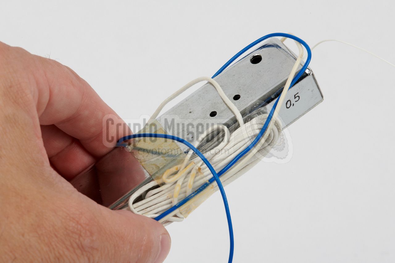
The Knowles BT1751 and BT1752 microphones are electrically identical.
The 1751 has its soundport at the end (at one of the short sides),
whereas the 1752 has the soundport at the side (i.e. in the middle of
one of the long sides). The KOS-11 featured on this page, is fitted
with a BT1752.
|
Below is the block diagram of the KOS-11 bug. At the left is an
externally connected miniature electret microphone, such as the Knowles BT1751.
It modulates a 24kHz sub-carrier generator, which in turn modulates the 81 MHz
crystal-controlled master oscillator. This technique is known as
subcarrier modulation,
or double FM, and is used to hide the audio from an eavesdropper.
The signal from the 81 MHz oscillator is multiplied by 12 and then
amplified, before it is applied to the ¼λ wire antenna at the right.
Note that apart from the desired signal at 973 MHz, it also
eminates some unwanted side products, caused by harmonics of
the crystal frequency.
|
Due to lack of selectivity in the multiplier stage of the KOS-11,
the transmitter produces signals at the following frequencies:
242, 322, 406, 486, 566, 649, 741, 811, 891 and 973 MHz.
These signals are all multiples of the 81 MHz oscillator frequency,
and apart from the final one (973 MHz), they are unwanted.
The lowest three frequencies (242, 322 and 406 MHz) could safely be
ignored as they were not detectable more than 1 metre away from
the KOS-11 transmitter.
The other frequencies (show in red) were more serious as they could
potentially interfere with regular radio and TV transmissions, which
might lead to discovery of the device. In particular the 566 MHz
signal was close to the carrier of the 2nd West-German TV channel
at 565.5 MHz. In close vicinity of a TV set, the KOS-11 could cause
the image to become darker [A]. When used from inside a car however,
no interference was noticed and the device was therefore approved.
|
|
The KOS-11 produces an output power of 10 mW. Depending on the position
of its antenna, this should be sufficient for a maximum range between
150 and 500 metres. In practice, the device was often installed between
the lining and the metal roof of a car, in which case the antenna was
somewhat obstructed by the roof. Experiments by the Stasi showed the
following results [A]:
|
150 m Good quality reception 250 m Good quality reception when using a Yagi antenna with the receiver 300 m Steady car: good reception, moving car: no reception 500 m Reception only when motor and lights are off (using Yagi antenna)
|
Although the KOS-11 operates at a very high frequency (972 MHz),
and very few people in the DDR were able to receive radio signals at that
frequency, there was always the danger that someone accidently
(or intentionally) picks up the signal from the bug and overhears the
conversation. This was particularly the case in the vicinity of the
West-German border, which was constantly under surveillance of West-German
intelligence service like the BND (civil)
and MAD (military).
In order to protect against eavesdropping, the Stasi
sometimes used audio-masking,
by which the audio is modulated onto a carrier
above the audible frequency range. This technique is also known as
subcarrier modulation or double FM (FM-FM). On a regular
receiver, an eavesdropper will only hear a silent carrier. In order to
hear the conversation, the seemingly silent signal has to be demodulated
once more. Although this defeats the average surveillance receiver,
the method was well-known by intelligence services at the other side,
and counter-measures were in place.
➤ More about sub-carrier audio-masking
|
For reception of the double-FM-modulated KOS-11, the Stasi used a
31215 or 31225 surveillance receiver, with either an external
demodulator (LWE6-1) or with an internally fitted module.
More information to follow
|
|
|
Despite the fact that SC-modulated bugs are often used by intelligence
serices, even today, the system is easily defeated with a professional
surveillance receiver,
or bug tracer.
One of the first bug tracers
that was able to demodulate an SC signal, was the
Scanlock Mark 3 in 1976.
Its successor, the ScanLock Mark VB
shown in the image on the right, can even discover the SC frequency automatically
and will find the subcarrier-modulated KOS-11 within seconds.
➤ More about the Scanlock range
|
|
|
|
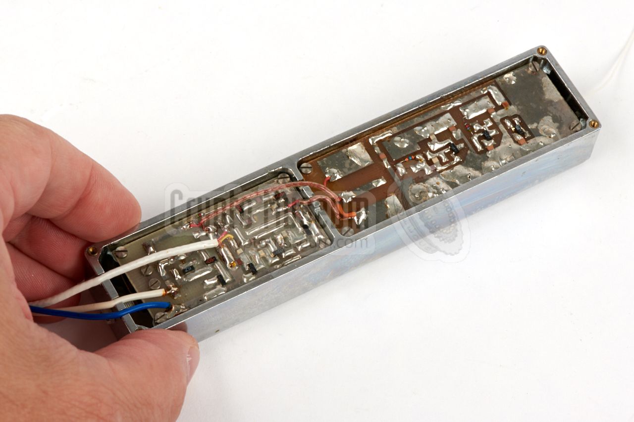
The KOS-11 is housed in a die-cast metalised plastic enclosure with two
compartments. It is closed with a metal panel at the bottom. The metal panel
is held in place by four screws in the corners. Removing these screws and
taking off the metal panel,
reveals the interior of the device.
|
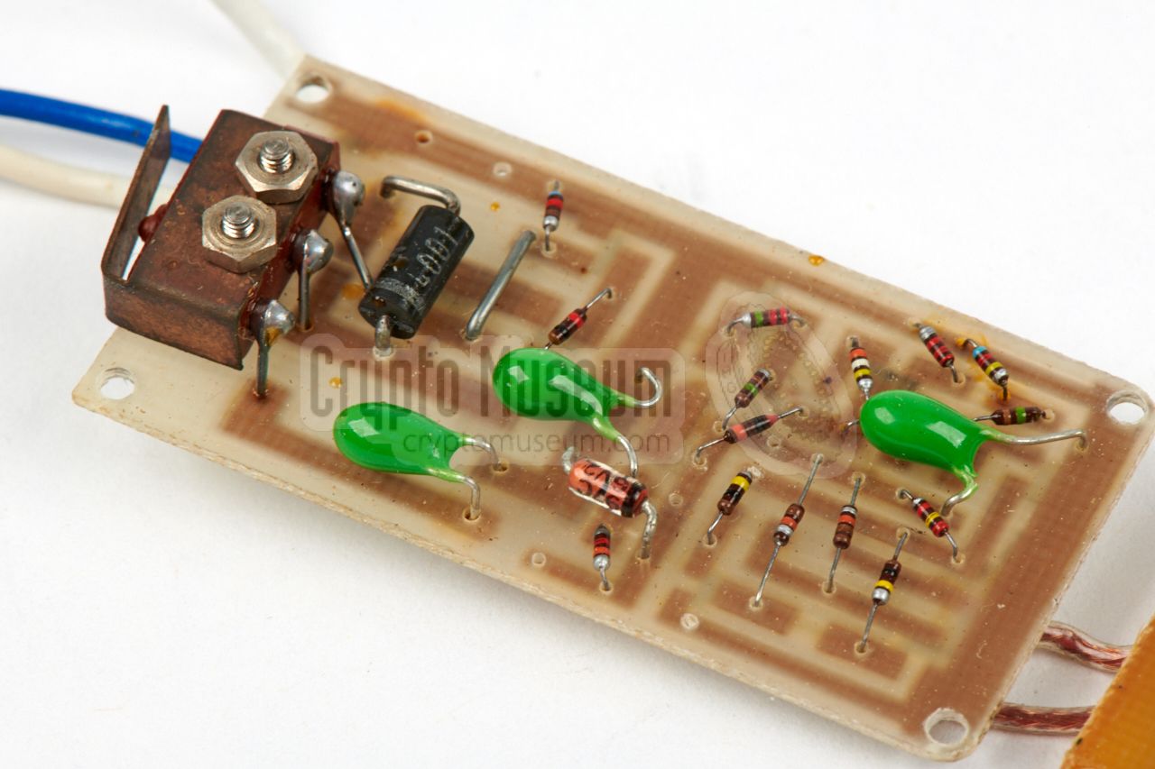
Inside the device are two printed circuit boards (PCBs): one holding the
subcarrier modulator
and a larger one that holds the transmitter.
Each PCB occupies one compartment of the enclosure,
and each one is held in place by four screws.
The PCBs have conventional components on
one side (top) and SMD parts
at the other (bottom).
When opening the case, the bottom side of the
PCBs is visible.
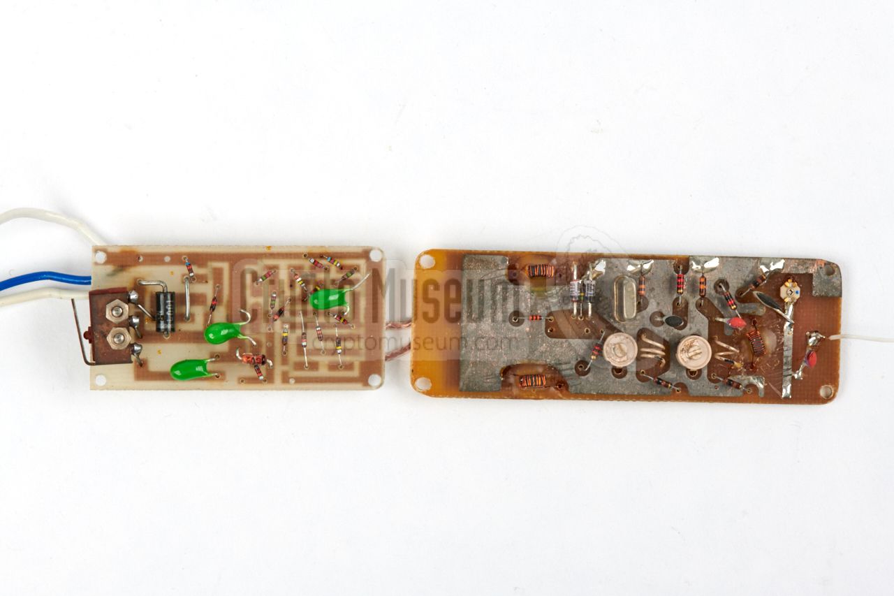
The image on the right shows the top side of the PCBs after removing
them from the enclosure. The PCBs are interconnected by means of two
shielded wires (audio and power).
|
|
|
At the left are two wires for connection of the supply voltage. The
white wire is for connection to the +12V rail of the car battery. The
blue wire is for connection to the (-) terminal of the battery (0V).
The electret microphone is connected via a long two-wire shielded cable.
The 1.5V power for the electret microphone is supplied by the device.
At the left is a screw-operated micro-switch that allows selection between
the raw 8-15V power, or (better) a stabilized 10.4V supply.
The device is well-made, but is a strange mixture of conventional
(through-hole) components and surface-mount parts (SMDs). Although the
use of SMDs generally leads to smaller devices, this is not the case here,
as the conventional parts
(in particular the crystal) need a lot of space.
Nevertheless, it gives a good impression of the state-of-the-art in
Bulgaria in the early 1980s, and clearly shows that they were capable
of making ever smaller listening devices (bugs).
|
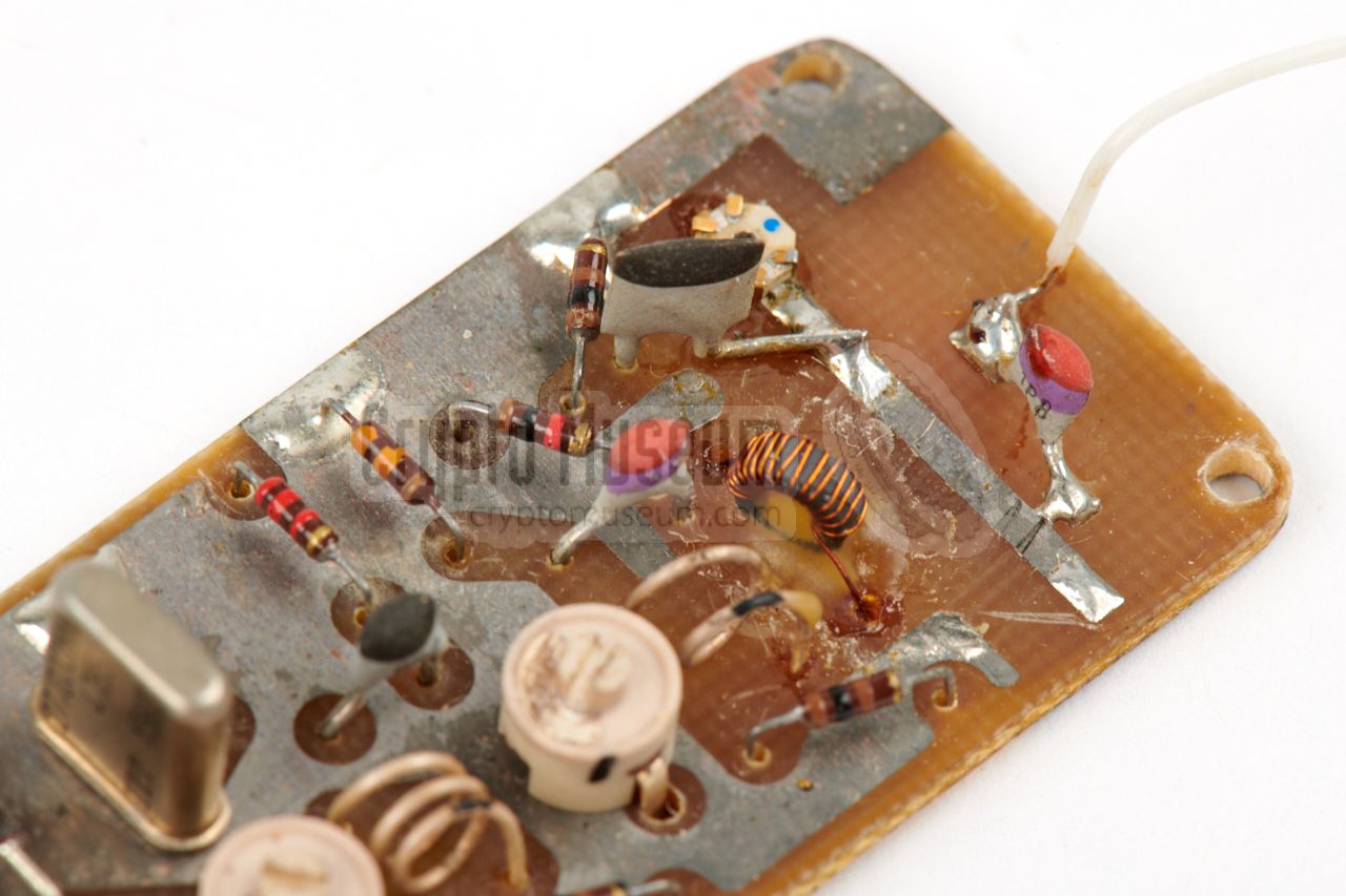
Below are the circuit diagrams 1 of the two PCBs of the KOS-11.
The first PCB holds the subcarrier modulator and consists of four sub-circuits:
A power stabilizer, built around T1 and T2, a microphone amplifier
(T3 and T4), a modulator (T5) and a 24 kHz subcarrier oscillator (T6 and T7).
The amplifier is suitable for connection of an electret microphone,
for which 1.5V is made. All circuits are powered by 6.2V.
The modulated 24 kHz sub-carrier signal is available at the right (SC out).
|
| |
PCB 1 - Amplifier and subcarrier modulator
|
At the top left is the raw battery input. A diode
in series with this rail protects the transmitter against revered polarity.
Also at the top left is a microswitch that can be used to select between the
raw +12V input voltage and the stabilized 10.4 V.
This switch is operated with a screw at one of the short sides of the
enclosure.
When the screw is not fully inserted, the stabilized 10.4V rail is selected.
This is the default setting. By turning the screw all the way in,
the raw battery voltage is supplied to the transmitter.
Be careful when doing this, as it might damage the transmitter.
The other PCB contains the actual transmitter, which consists of four
sub-circuits: a modulator, a crystal oscillator, a multiplier and an RF
amplifier. The circuit is powered by a stabilized 10.V DC voltage, that is
supplied by the other PCB. Central to the circuit is a crystal oscillator
that uses a 27.000 MHz in its 3rd overtone to get a stable 81 MHz signal.
The crystal is FM-modulated by means of two varicap diodes (V1,2) to
which the subcarrier output of the other PCB is supplied.
In the 2nd stage (T2) the 81 MHz signal is multiplied by 12 to get the
required 972 MHz signal. The last stage (T3) finally amplifies the signal
to antenna level (approx. 10 mW). The antenna is connected to a tap on
the stripline coil in the tuned circuit of T3. The circuit has three
adjustable capacitors (C4, C7 and C12) that are accessible via holes in
the top of the enclosure.
The three SMD transistors
are all marked -P1- which refers most likely to the RF transistor
BFR-92
[B].
|
 |
-
As the original technical documentation has not been recovered, the
circuit diagrams above have been created by us, by carefully studying
the PCBs and making some educated guesses.
|
Power supply 8—15V DC (typically 12V from a car battery) Current 11 - 40 mA Frequency 973 MHz (from 81 MHz crystal) HF power 10 mW Modulation FM (F3) Masking FM-FM subcarrier modulation Subcarrier 24 kHz Temperature -10°C — +55°C Microphone Knowles BT1751 or similar Dimensions 130 x 28 x 19 mm Weight 64 grams
|
972.2 MHz Crystal: 27.000 MHz 973.81 MHz Crystal: 27.050 MHz
|
-
Document obtained from BStU [2] and kindly supplied
by Detlev Vreisleben [1].
|
-
Full name: Bundesbeauftragte für die Unterlagen des Staatssicherheitsdienstes
der ehemaligen Deutschen Demokratischen Republik
(DDR) —
Federal Commissioner for the Records of the
State Security Service
of the former German Democratic Republic (GDR) —
officially abbreviated to BStU.
|
|
|
|
Any links shown in red are currently unavailable.
If you like the information on this website, why not make a donation?
© Crypto Museum. Created: Wednesday 08 August 2018. Last changed: Wednesday, 05 November 2025 - 11:40 CET.
|
|

|
|
|