|
|
|
|
|

|
|
USSR Cold War R-354 → ← R-350
Russian spy radio set (Eagle) Mark II
The R-350M was a Russian spy radio set
that was developed in the former USSR around 1957.
It was the successor to the earlier R-350
and was developed at the KGB Research Institue, probably
in Kuchino (near Moscow) [1]. It was not only used by the USSR, but also
by the other countries of the Warsaw Pact, such as East-Germany, which is why
it was produced in rather large quantities.
|
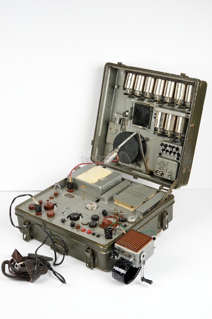
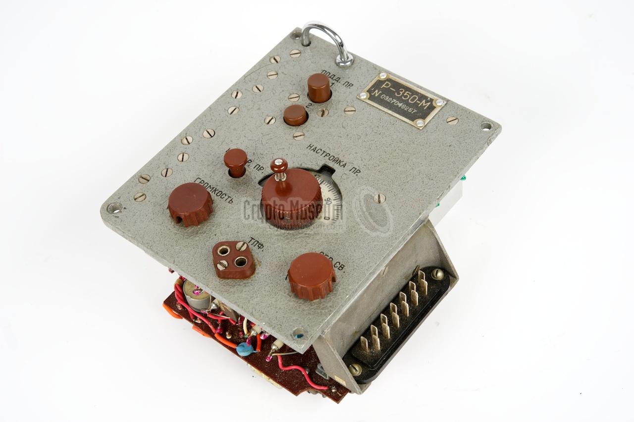
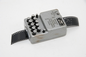
Like its predecessor, the R-350, the R-350M was available
with a Russian or English front panel. The latter was used for foreign
'activities'. The image on the right shows a typical R-350M with Russian
front panel, ready for use.
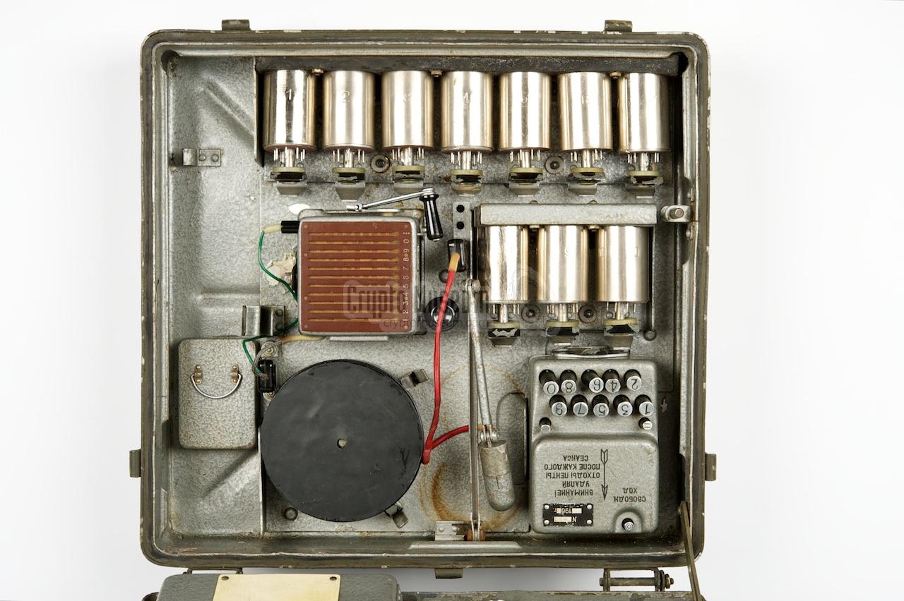
Whilst the R-350 contained large valves (tubes) that could be
accessed from the front panel, the R-350M is completely built around
miniature valves with wire-terminals.
These can no longer be swapped easily in the field.
Furthermore, the rectangular transmitter filter (coil)
is replaced by a cylindrical one. In total, 11 coils are supplied,
one of which is installed in the transmitter.
The R-350M uses the same burst encoder
and burst transmitter as the R-350.
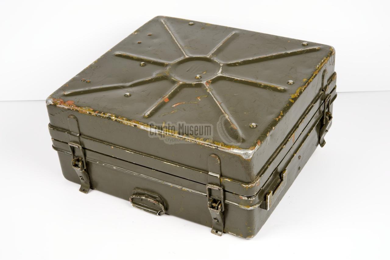
When unused, these are stored inside the top lid of the case,
together with the spare transmitter coils, a film container, the antenna,
the headphones, an overhead light and some spares.
The burst transmitter is attached to the right of the case.
|
|
|
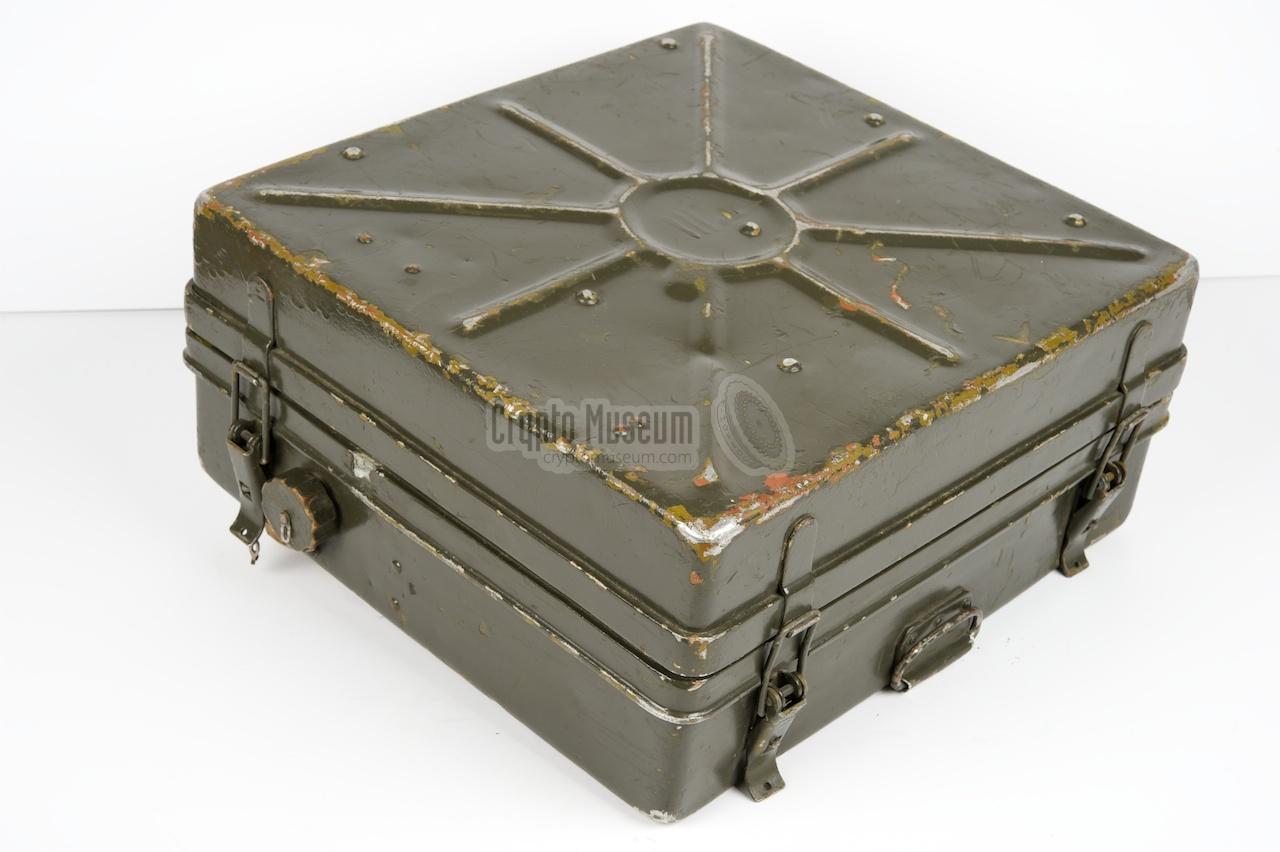
The R-350M is a completely self-contained transceiver,
with built-in battery
and power supply unit (PSU).
The latter produces all the voltages
necessary to drive the transmitter and receiver valves.
The battery compartment has a built-in heater,
to allow the battery to be used at extremely low temperatures.
The heater it powered by the battery itself.
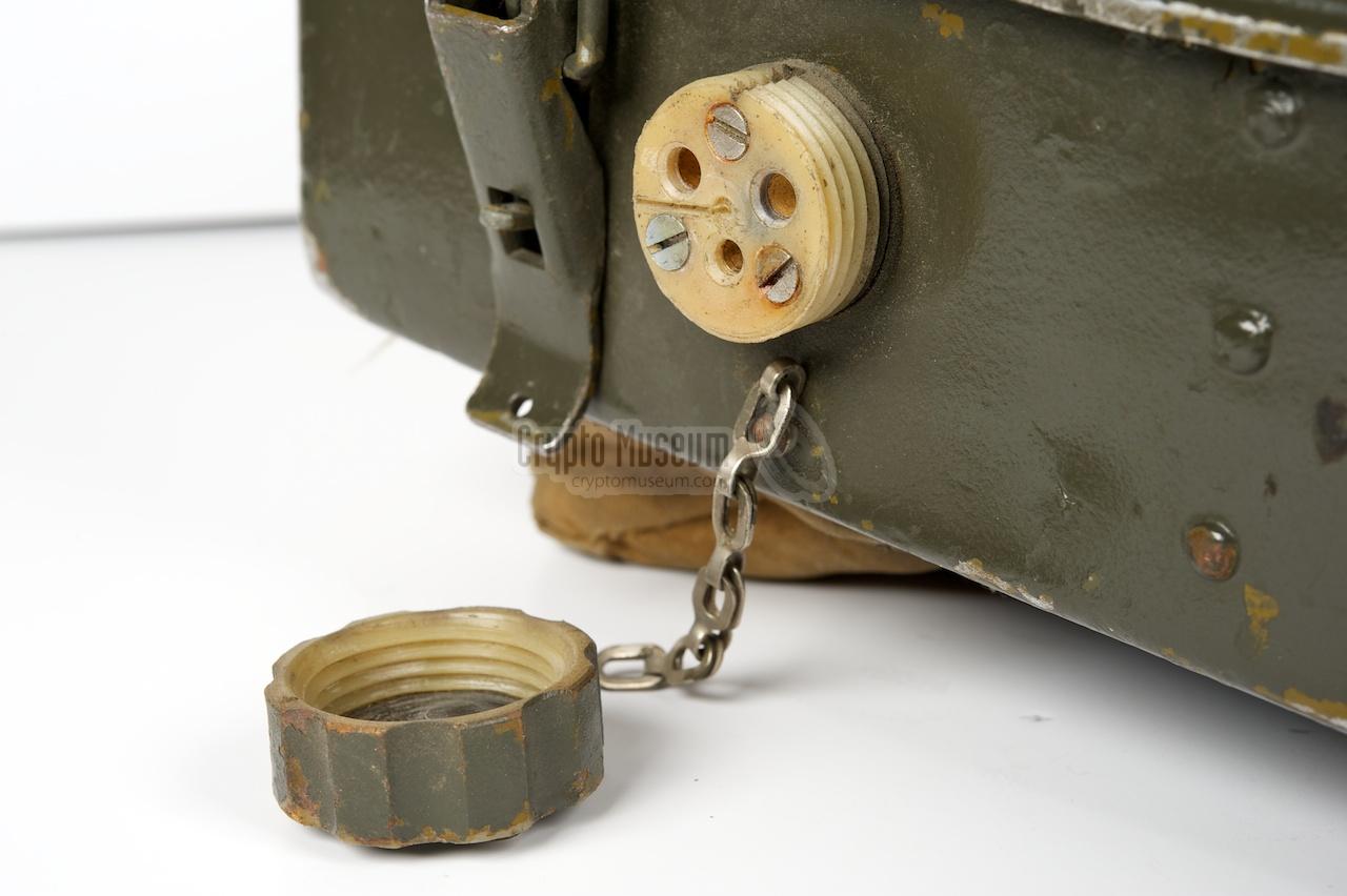
The radio can also be driven from an external 6V power source,
which is connected to a socket at the left side.
In the early 1960s, the R-350/R-350M
was replaced by the improved
R-354 (Schmel).
It was smaller and had a motor-driven burst transmitter.
Furthermore it only used half the amount of film compared to the
R-350. Like the R-350 it was powered by an internal 6V battery.
|
|
Below are some audio samples of the R-350M, recorded by karsten Hansky in
Germany [5] in June 2014. The radio was connected to a dummy load and an
ELAD FDM-S1 was used to receive and record the signal. Further sound
processing was done with Audacity.
|
|
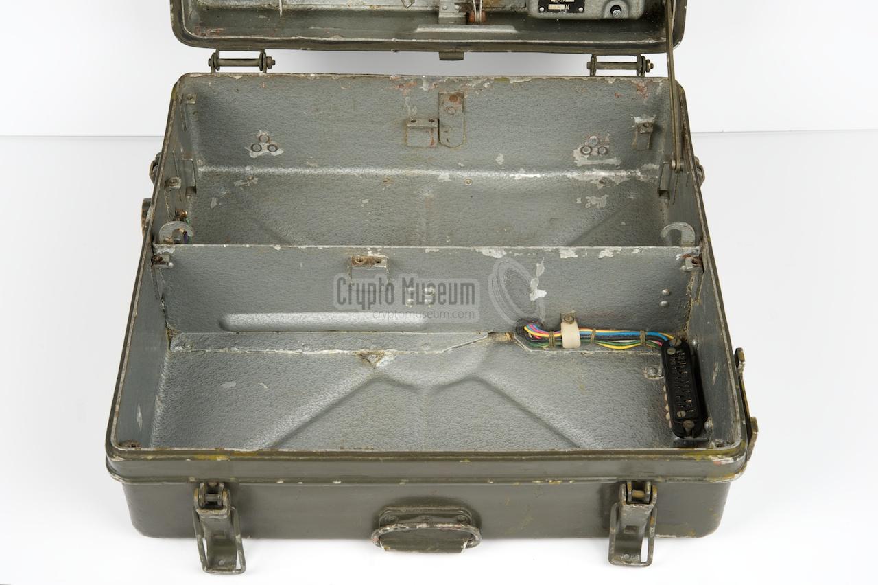
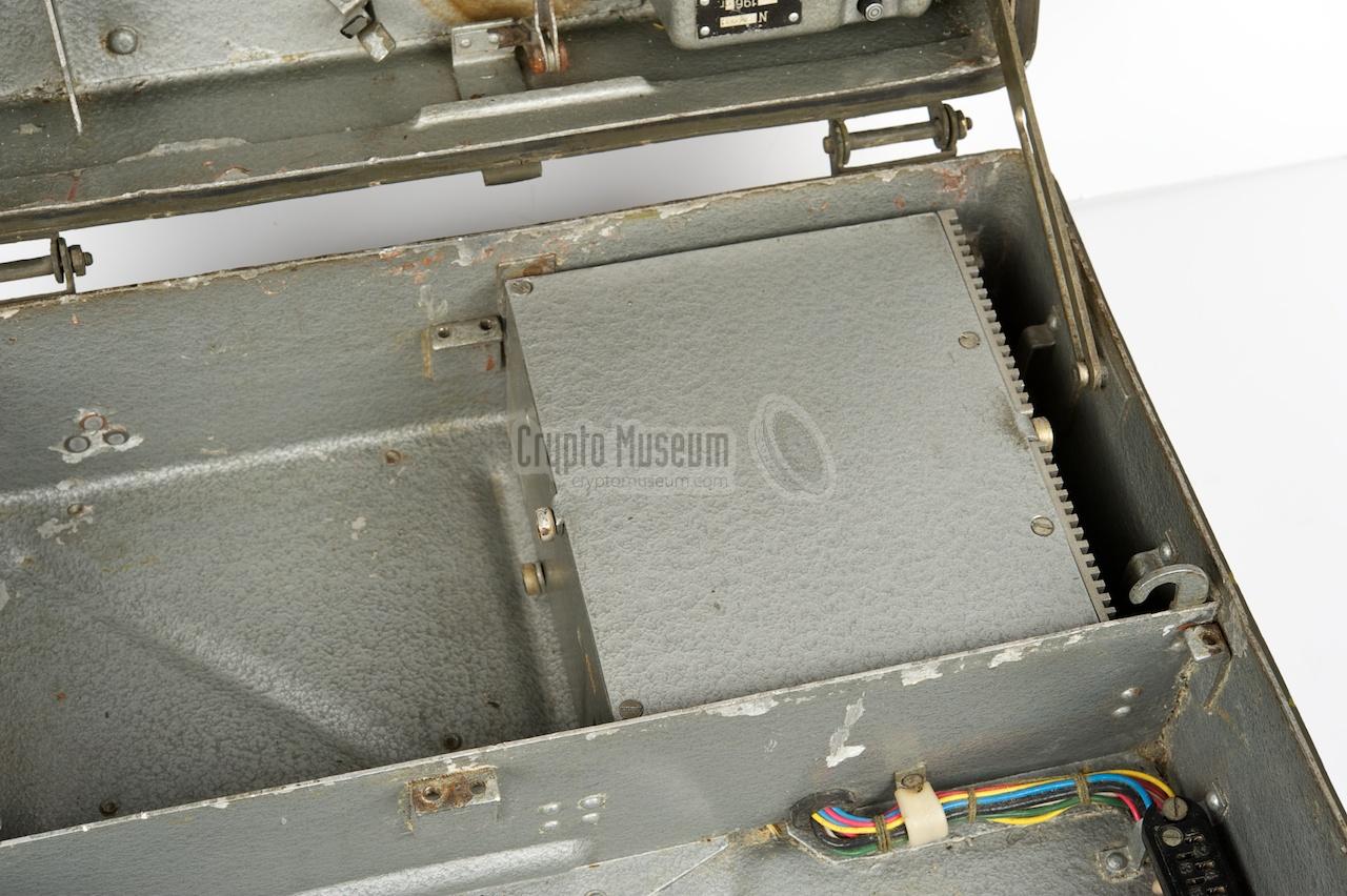
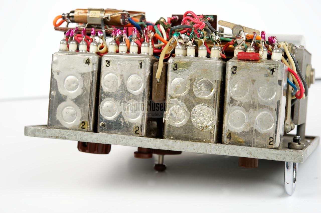
The R-350M is wired in such a way, that the transmitter, receiver, battery
and power supply can easily be removed. Once the bolts
at the edges of each block are removed, the module can be lifted out.
The modules are connected together by means of sockets that are present inside
the pre-wired case. The image below gives a good view at the sockets.
|
|
The transmitter can be adjusted to any frequency between 1.8 and 12MHz,
divided over 11 ranges that are selected by means of plug-in coils.
The circuit is built around five 1SH29B (1Ж29Б)
and three 1P24B (1П24Б) valves [4].
The latter are connected in parallel in order to produce an output power
of 6W, which is suitable for a maximum range of 1000 km [3].
|
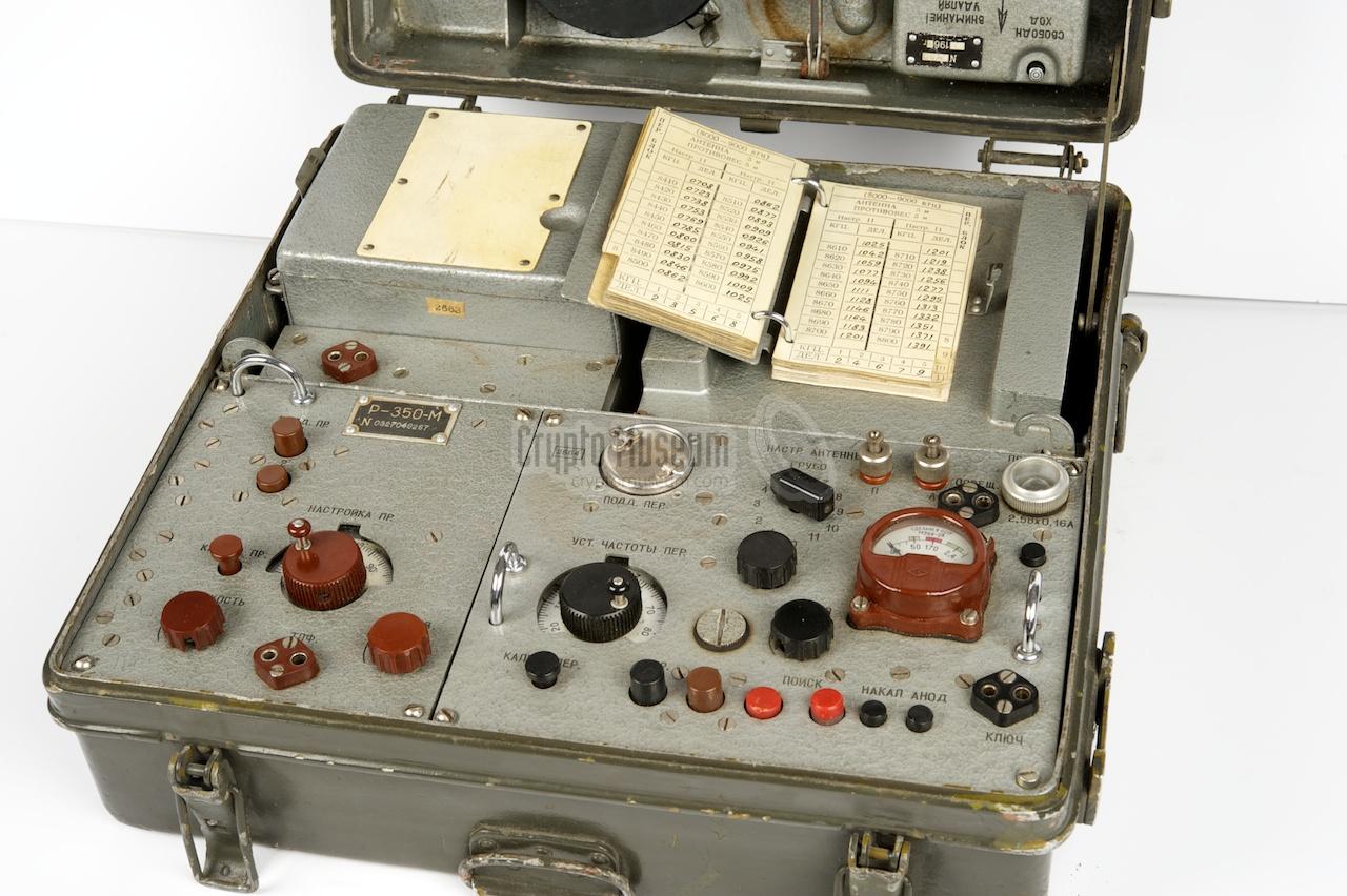
For each range and frequency, the antenna must be tuned for maximum
performance. A small hand-written booklet with suitable
tuning charts
is mounted on top of the power supply unit.
The image on the right shows the transmitter once it is removed from the case.
At the top left is the removable filter (coil). The connection for the morse
keyer is at the bottom right.
The transmitter is capable of sending a 70Hz 'homing signal' that is
used by the home office to automatically start a disk-recorder.
|
|
|
The transmitter is capable of sending data (CW) at 100 to 150
groups per minute (each group is 5 digits).
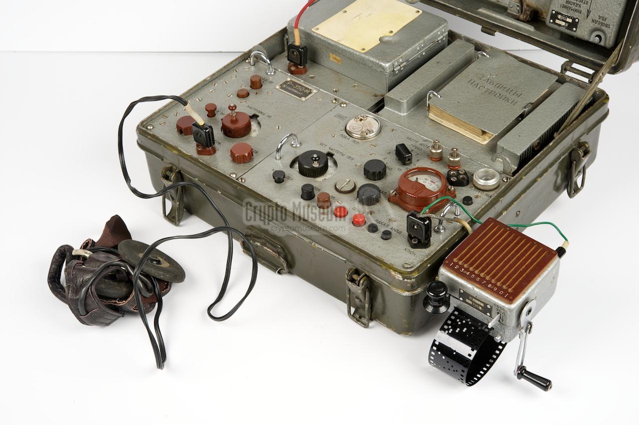
At the top right, just below the antenna tuning lamp, is a black push
button that is used to completely shut down the radio when the top lid
of the case is closed. The buttons at the bottom are used to select
the mode of operation (send, receive, homing, etc.).
|
The receiver is a superheterodine design with an intermediate frequency
of 750kHz [4],
built around five 1SH29B (1Ж29Б) miniature valves.
It can be adjusted to any frequency between 1.8 and 7MHz,
divided over two ranges (1.8-2.52 and 3.52-7MHz).
The range is selected with two push-buttons at the top left.
|
|
|
|
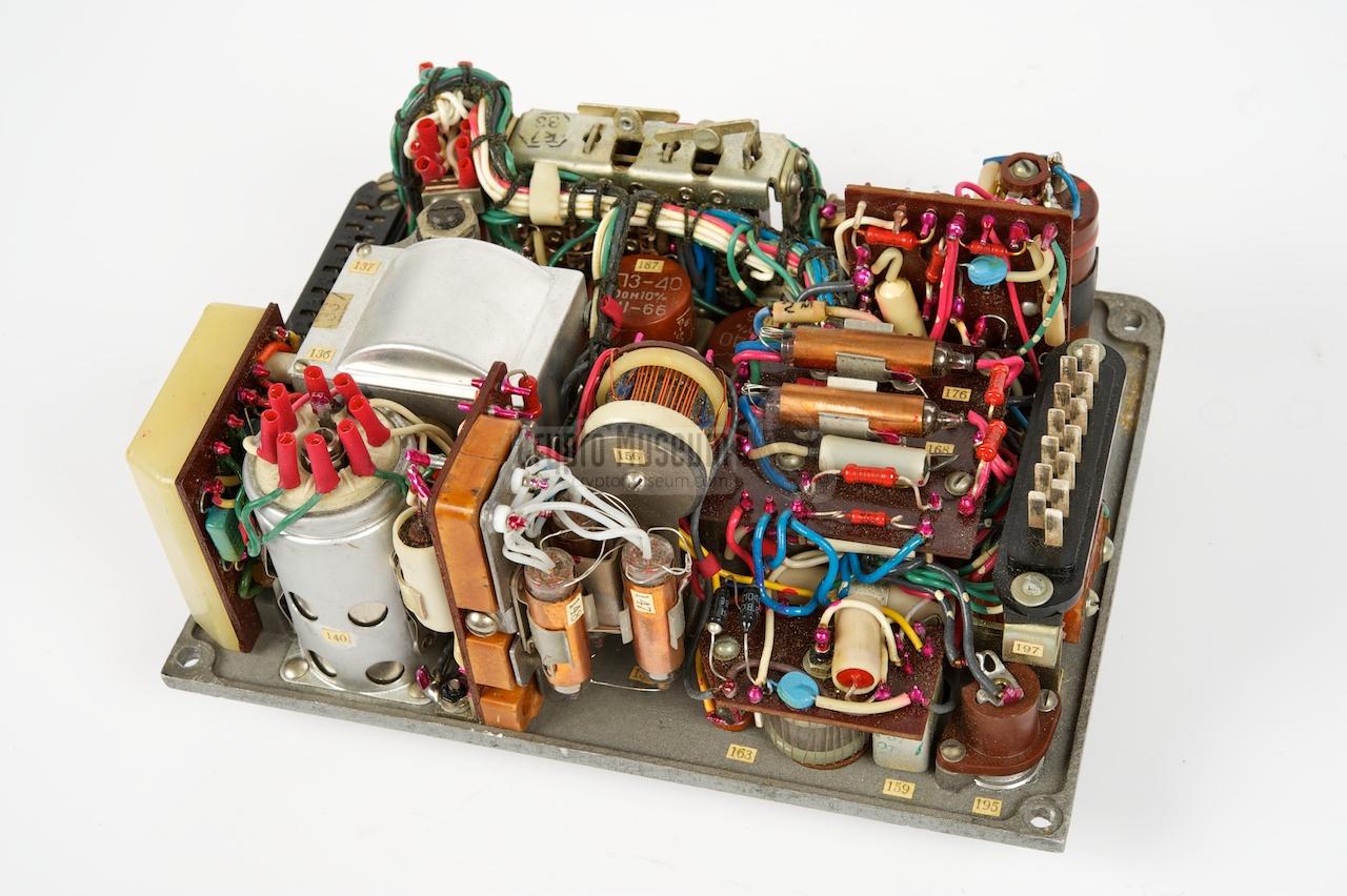
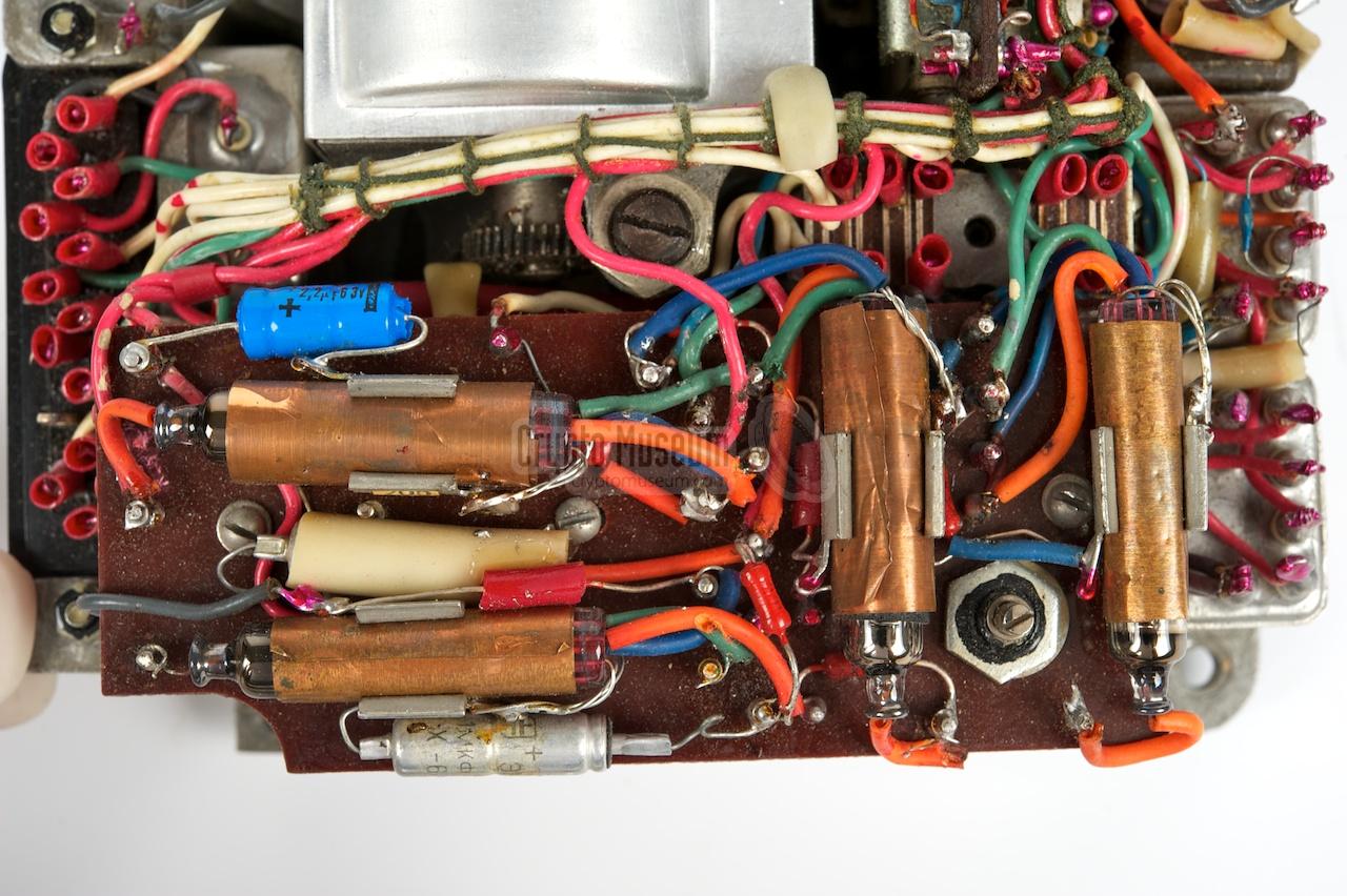
The power supply unit (PSU) is completely transistorized, which is quite
unique for its age (late 1950s). The aluminium case is designed in such
a way that it acts as a heatsink for the 10 power transistors that are
mounted on one side. The image below shows the side with the transistors.
|
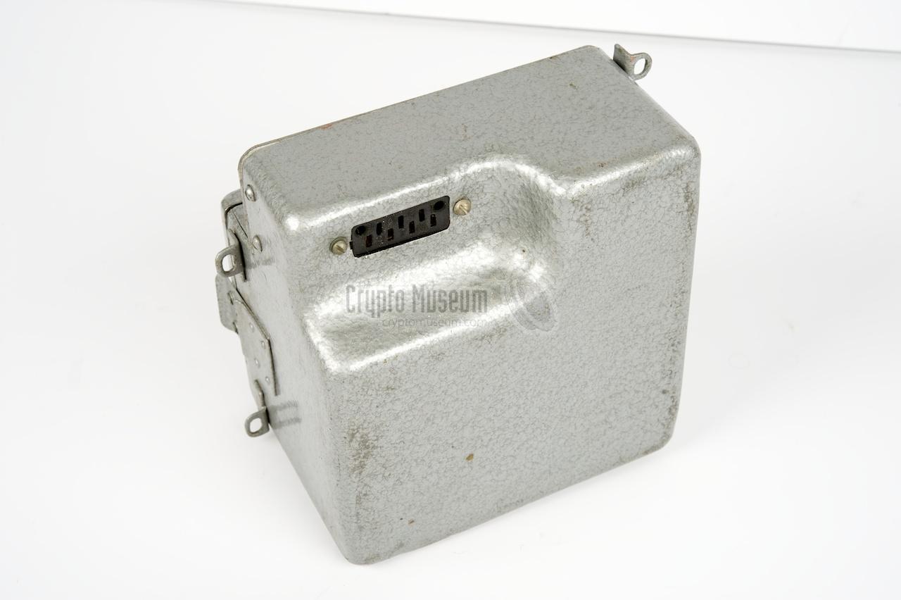
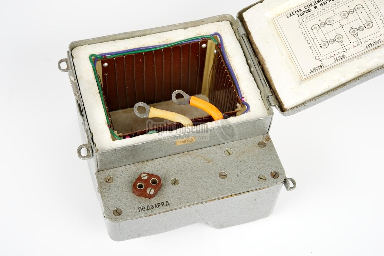
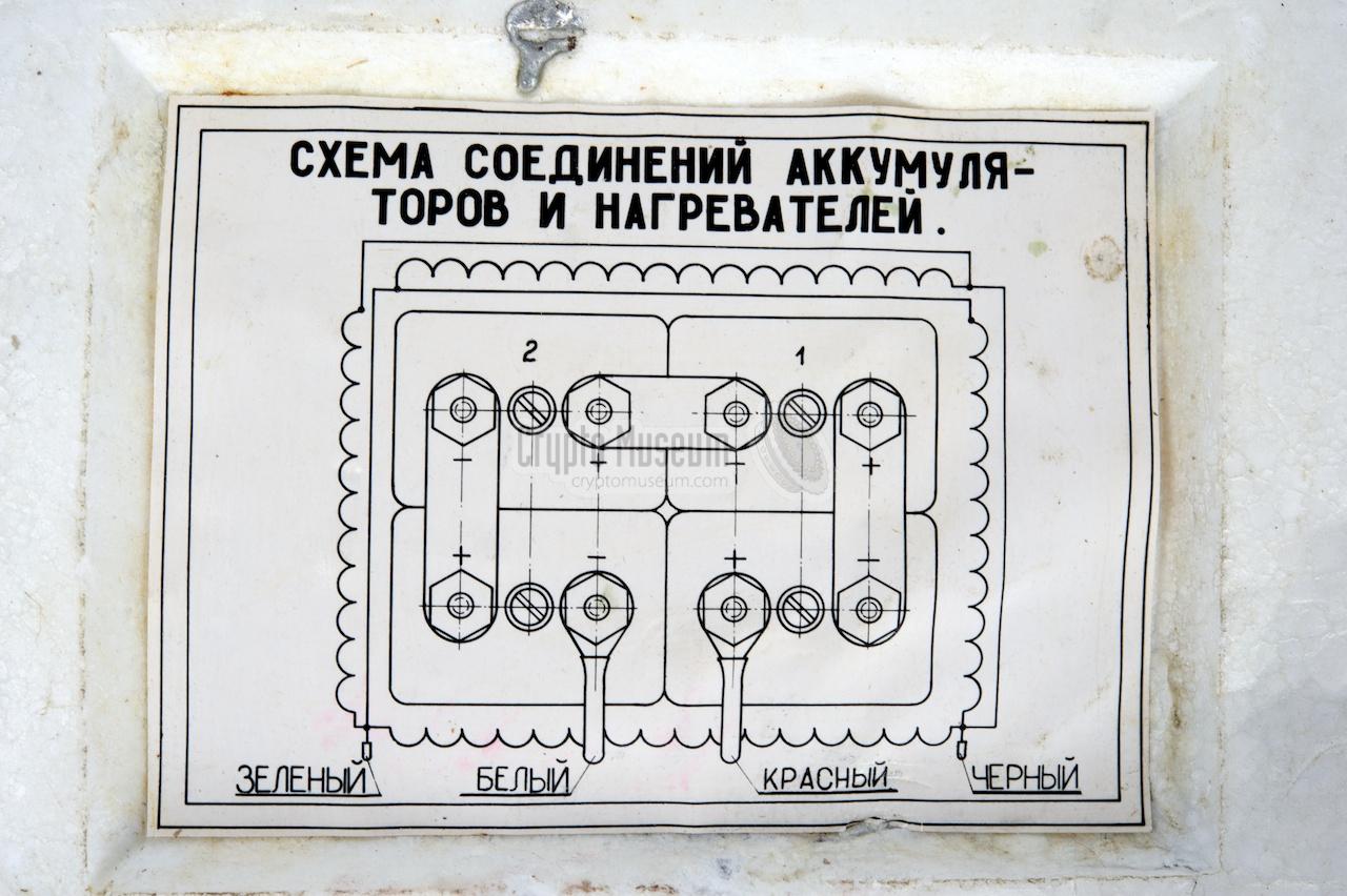
The R-350M can be powered by a built-in 6V battery, which is located
at the rear left. The battery itself is housed inside an
isolated box.
In order to allow the radio to be used at extremely low
temperatures, the battery box has a built-in heater
that is powered from the same battery.
At the bottom of the battery box is a large socket
that connects it to the rest of the radio via the pre-wired case.
The white plastic plate on the top lid of the box, is a notepad that can be
used, for example, to write down call signs and frequencies.
|
|
|
|
In the image below, most (but not all) accessories are present.
At the top left are the 10 removable coils used for selecting the
frequency range of the transmitter. At the bottom right is the
burst encoder (puncher) which allows a (coded) message to be recorded
onto photo film.
To the left of the puncher is a circular container with a fresh supply
of unused film. Above the container is the morse key with built-in
hand-operated burst encoder.
|
|
The following accessories are usually stored inside the top lid:
|
|
|
|
At the far left is a small metal cabinet in which spare light bulbs and
fuses are stored. The wire antenna is not shown here. It is normally stored
at the left, taking up all space from top to bottom.
The headphones are not shown either.
They are usually stored in between the container and the puncher.
|
Each message is first translated into a series of numbers. This is usually
done with some kind of cipher system, such as a simple matrix or the
unbreakable One Time Pad (OTP).
The numerical message is then stored on a a standard 35 mm photo film
by punching a series of holes in it, using the device shown here.
➤ More information
|
|
|
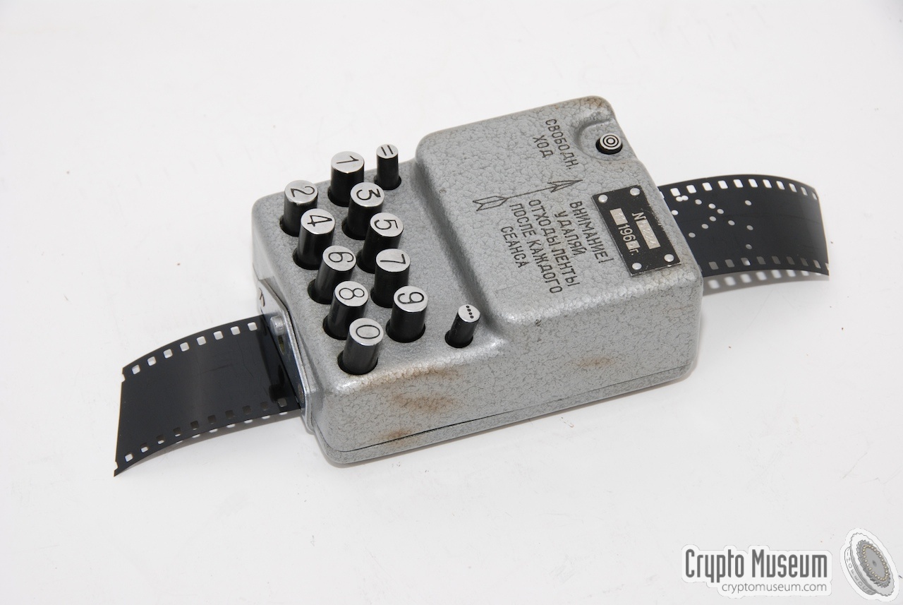
The R-350M is supplied with an external morse key with integrated burst
transmitter. Photo film with the punched numerical message can be fed
into a narrow slot at the front of the morse key.
A small crank is then used to feed the film through
the transmitter at a constant speed between 100 and 150 groups per minute.
➤ More information
|
|
|
|
Almost any type of headset can be used with the R-350M.
In most cases, a common USSR military headset was supplied, with rubber ear
pads and elastic head bands. Such headsets are commonly used with military
radio sets in tanks etc. Headsets are connected to the two-pin socket on
the left of the front panel of the radio.
|
|
|
|
|
|
Any links shown in red are currently unavailable.
If you like the information on this website, why not make a donation?
© Crypto Museum. Created: Wednesday 06 June 2012. Last changed: Saturday, 14 November 2020 - 17:18 CET.
|
 |

|
|
|