|
|
|
|
|

|
|
Finland Sweden Kyynel M-11 → ← M-7
Finnish (Swedish) WW-II spy radio set
Kyynel
M-10 and M-11 were compact spy radio transceivers,
operating in the 80m short wave band between 3800 1 and 4800 kHz,
developed and built by the Finnish Army Depot Company Munkkiniemi
near Helsinki (Finland) during WW-II.
Despite the fact that Finland was collaborating with Germany,
they secretly built the a crystal version of the set, the M-10X,
for the Swedish Army, where it was known as Radio Station 1 W Br m/44.
The radio is also known as VRHAG.
Post-war versions of this radio set, stowed in a metal container,
are known as M-11 and M-11X.
|
The radio set was the successor to earlier Kyynel models and was
basically a combination of the earlier M-5 transmitter
and the M-7 receiver. It produced a maximum output power of 1W
(in practice 0.3-0.5W) and was
intended for long range intelligence and guerrilla patrols [1].
The M-10 measure only 5.5 x 12 x 24 cm and weighs 1.6kg.
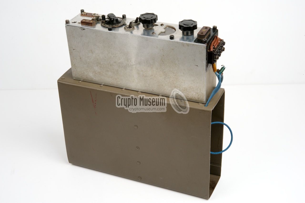
It was usually mounted on top of a
cardboard battery box (see below).
When not in use, it was stored in a
cardboard container, together with the
accessories and
passport. The image on the right shows the M-10X version.
|
|
|
Kyynel M-10 was introduced in 1942 and is also known as VRHAG.
A later version, Kyynel M-11
was produced until the late 1950s.
It is basically identical to the M-10,
with the exception of the filament voltage (LT) – 3V rather than 1.5V
– the container and the crystal socket. Like the M-10X, the M-11X was the
crystal version of the set. The M-11 was also known as VRHAI
[1].
The radios were available in a single-band and in a two-band version.
The M-10 and M-11 were designed for long distance communication
(150 - 500 km), and a total of ~300 units was manufactured [2].
|
-
The receiver has a slightly wider range from 3600 to 4800 kHz.
|
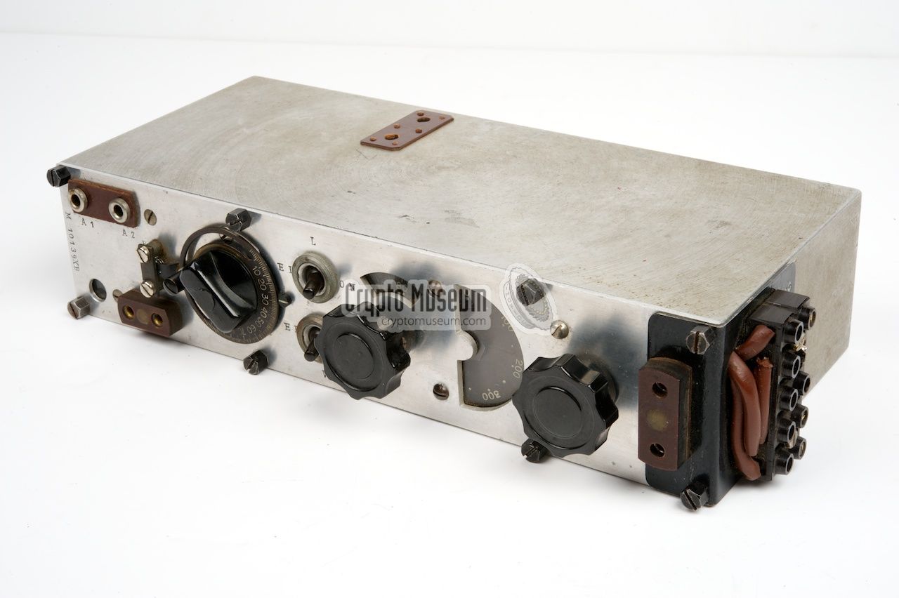
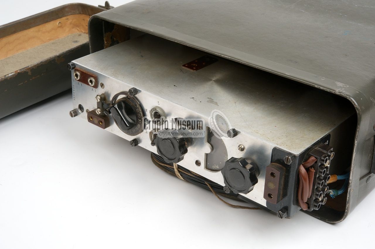
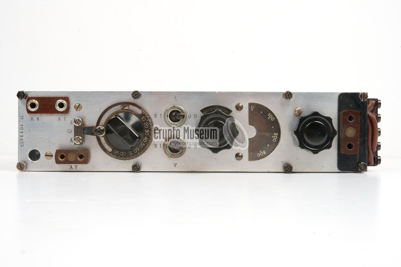
All controls and most of the connections are at the front panel. The crystal
is inserted in a socket on the side of the unit. The batteries are connected
to the contact strip on the right hand side.
A morse key can be connected at the front left and a suitable pair of
headphones at the far right.
A suitable antenna, consisting of two 20 meter wires, should be connected
to the socket at the top left. The antenna wires can be adjusted to four
different lengths, depending on the frequency in use. A tuning chart,
containing the desired antenna length and the correct setting of the antenna
tuning dial, was supplied with the radio.
The manual explains how to
set up the antenna.
|
- VRHAG — M-10
Initial version, first made in 1942, based on the M5 transmitter and
M7 receiver. Supplied in a cardboard container. 25 units were
sold to Sweden during the war. Also known as VRHAG and as P-12-24.
- VRHAG — M-10X
Crystal version of the M-10, first made in 1944. Towards the end of the
war, some M-10X units were manufactured in Sweden, after the workshop had
been relocated. The serial numbers of the sets that were made in Sweden
have the suffix 'B'. The set featured here is of this type
and was made in Sweden. It has serial number M10139XB.
It was also known by its Swedish designator 1 W Br m/44.
- VRHAI — M-11
Post-war version of the M-10, first made in the early 1950s. Housed in a metal
container and uses 3V for the filaments of the valves, rather than 1.5V
(filaments in series). Also known as VRHAI.
- VRHAI — M-11X
Post-war version of the M-10X, first made around 1955. Suitable for the smaller
CR-5/U crystals that were available from American military surplus after the
war. The crystals of the M-10X can not be used with the M-11X.
|
Kyynel is the Finnish word for tear. It was used as the codename
for a range of clandestine radio sets. Development of the range started before the
winter war of 1939, when the Army recognised the increased need for light-weight
transceivers.
Until that time, all Finnish radio sets used by the Army,
had been heavy and bulky, and
were unsuitable for remote patrol liaison officers [2].
As radio amateurs already had valuable experience with radio communication under
varying conditions, the development team consisted mainly of radio hams. The
group worked under supervision of reserve-captain Holger Jalander and the initial
designs were largely based on existing German agent radio sets weighting
15kg. These developments were not very successful.
An additional problem was that suitable components and tools were difficult to
obtain at the time. Nevertheless, the team succeeded in producing a small
portable radio station and the first prototypes were tested at the beginning
of 1940. In the early days, construction work on the radios was carried out
in the utmost secrecy in a heavily guarded cottage at Lake Tuusula.
The enterprise was later moved to a better location in Röykkää and ultimately
to Nystad [2].
Already in the early stages of the development, Jalander decided to use
die-cast aluminium enclosures for the radios. Not only did he save on
weight this way, it also allowed the radios to be made water-tight.
The developments eventually resulted in the production of the early Kyynel
models M-4, M-5 and TÖPÖ (stump) which
used German valves
(e.g. produced by Telefunken).
|
In 1942, the earlier models were followed by the M-10
which was effectively
a combination of the M-5 transmitter
and the M-7 receiver. The radio set was designated VRHAG (P-12-24)
and the first wiring diagram was made on 13 July 1942. 1
A few years later, a crystal version of the radio had to be developed,
but it appeared to be very difficult to obtain crystals at the height of
WW-II.
Again, radio amateurs came to the rescue when reserve-lieutenant
Toivo Leiviskä, an electronics engineer, demonstrated how they could
be made manually [2]. This resulted in the M-10X model.
|
|
|
The crystal-driven M-10X was not only used in Finland, but was
also sold to Sweden in late 1943 and early 1944. The first 25 units
were delivered prior to Operation Stella Polaris in Finland, followed
by another 75 units that were produced by Major Rangvald Lautkari
in his workshop in Lindingö.
The components for this production run had to be shipped
over water from Nystad [2].
The serial numbers of the radios that were manufactured in Sweden, are
suffixed by the letter 'B'.
After World War II had ended,
production of the M-10 and M-10X continued,
as the Cold War had meanwhile started.
The M-10(X) was eventually modified and continued life as the
M-11 and the M-11X — suitable for modern
crystals — both of which remained in production until ~ 1959.
|
-
The M10 radio set was already in use as this point, as the drawing
refers to carrying case for model M10 that was also available [2].
|
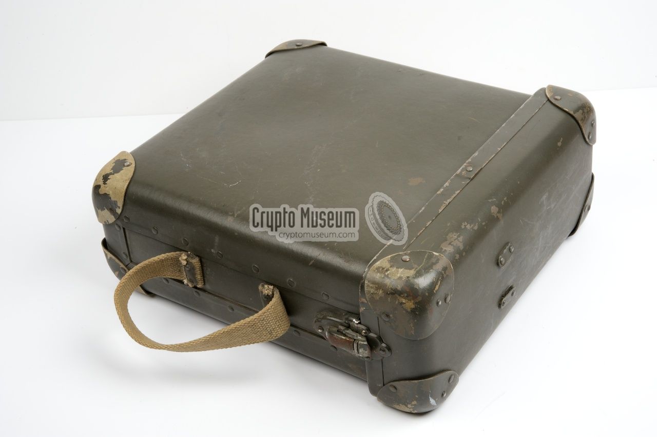
When not in use. the M-10 was usually stored in a cardboard container with
reinforced corners. The container had a canvas carrying strap on one of its
sides and a removable lid at the top. The lid was held in place by two clip locks.
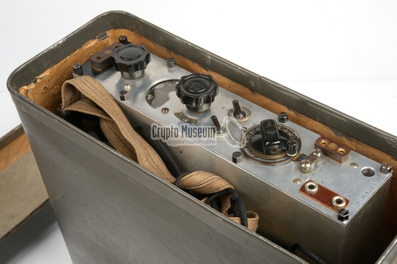
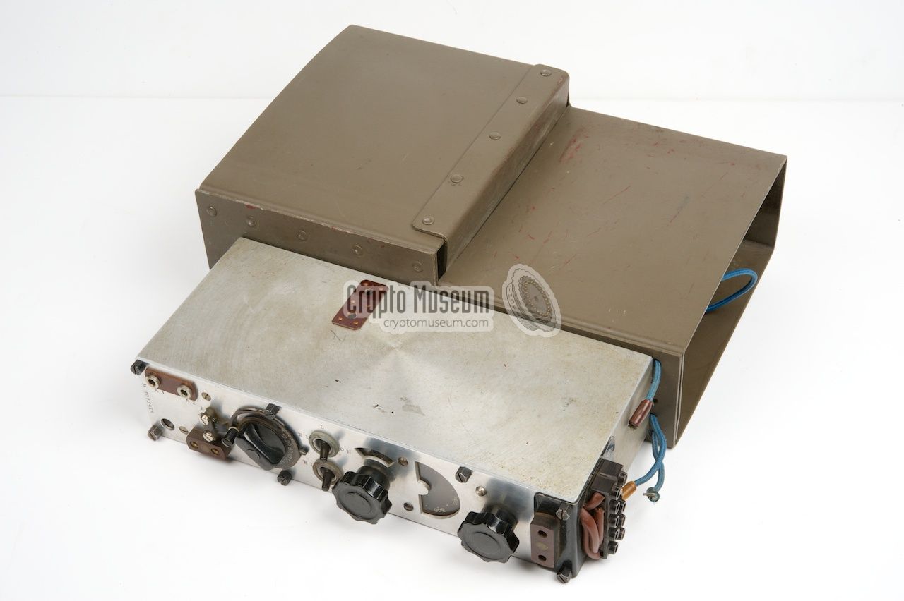
Later versions of the M-10 (and M-11) were stored in a more robust metal
container, allowing the radio to be stored for extended periods of time in
a moisty place.
|
|
|
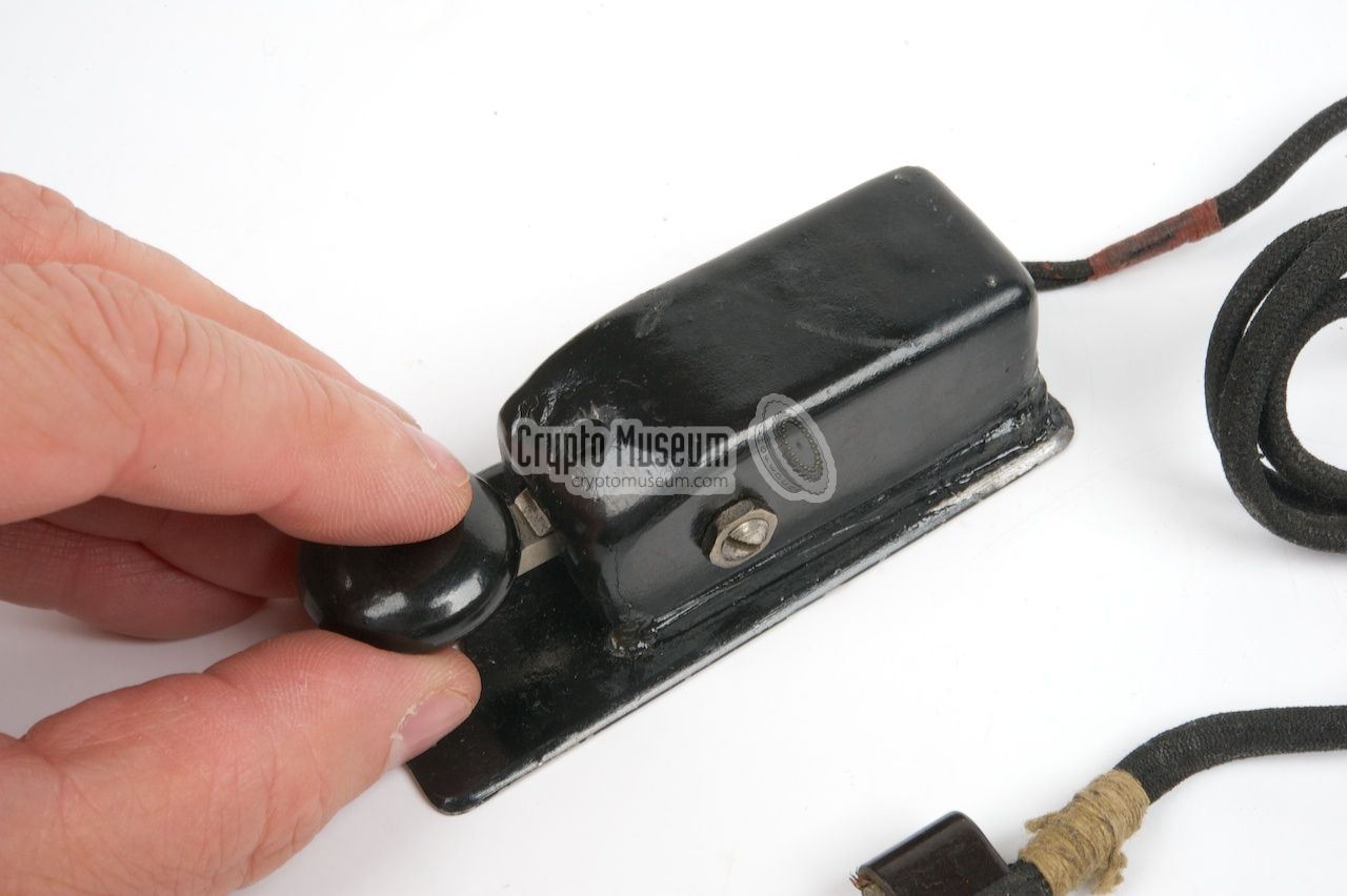
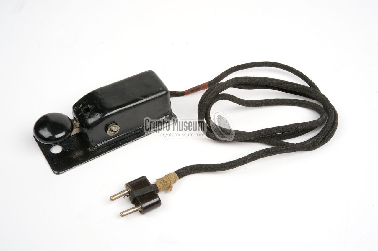
A morse key can be connected to a two-pin socket at the bottom left of
the front panel. The key is connected in series with the anode of the
DLL 21 transmitter valve and directly switches the 120V supply
to the transmitter on and off.
The image on the right shows the small morse key that came
standard with the M-10X. Please note that the cover needs to be present
when operating the Kyynel M-10, as the key directly switches the HT voltage.
|
|
|
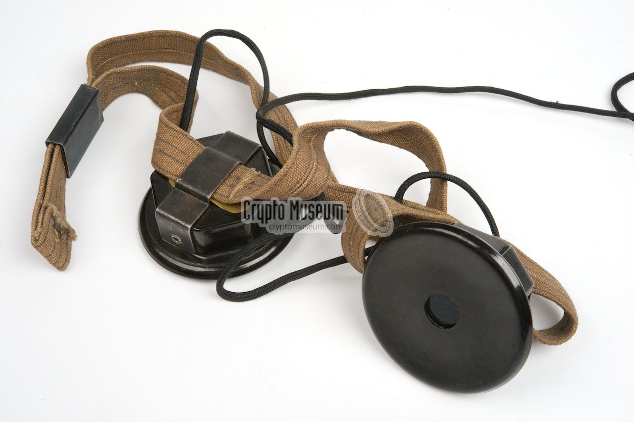
The Kyynel M-10X was supplied with a pair of 600 ohm high-impedant
speakers, mounted to a canvas strap that allows them to be worn on
the head. The headphones are connected to the 2-pin socket on the right
of the front panel.
The image on the right shows the original headphones that were supplied
with the Kyynel M-10X featured on this page.
|
|
|
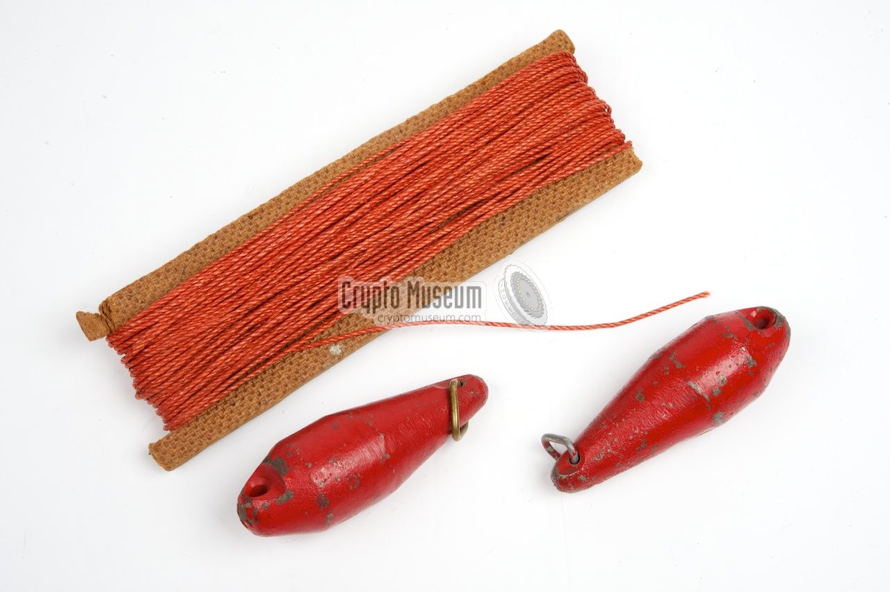
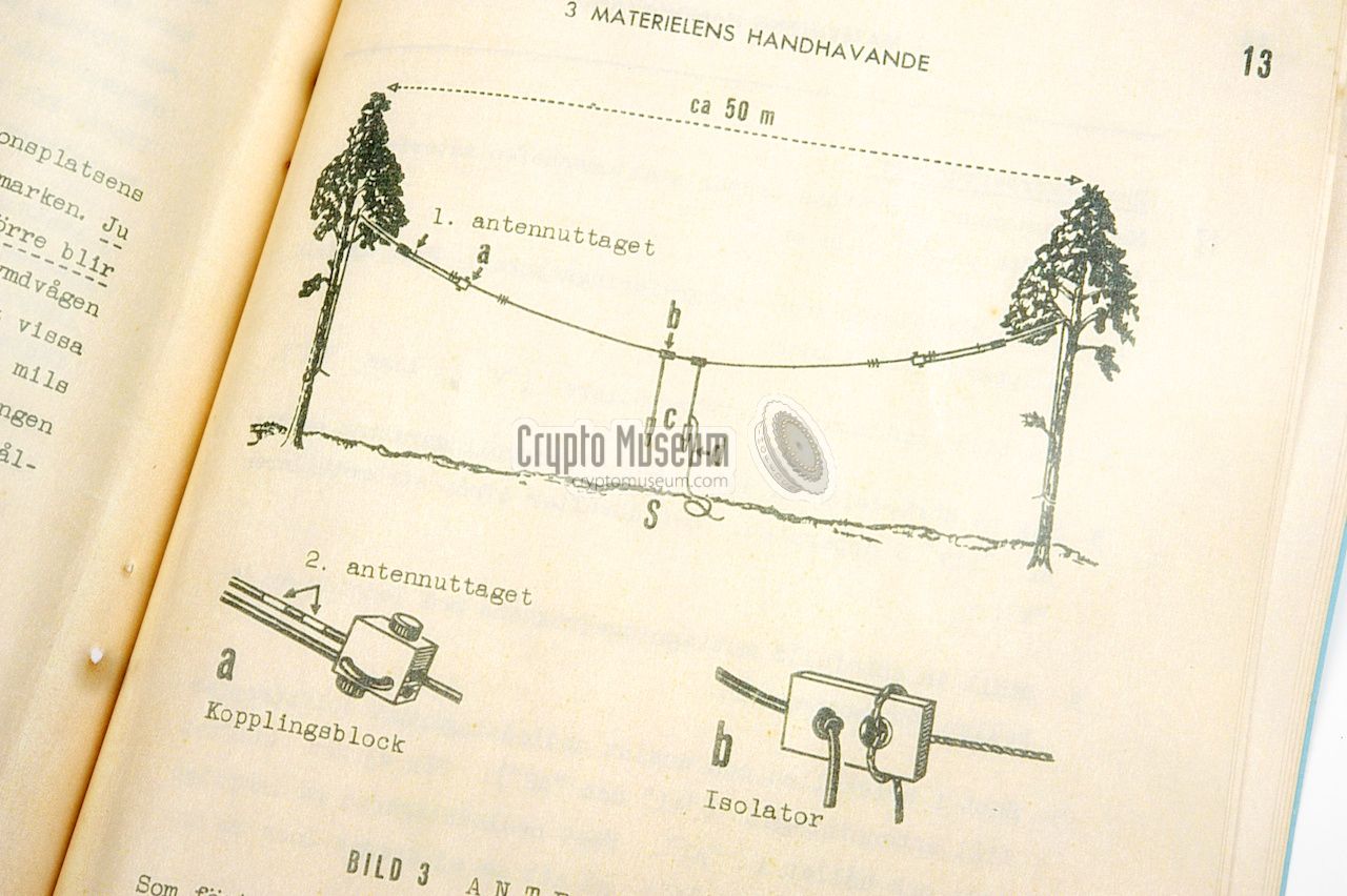
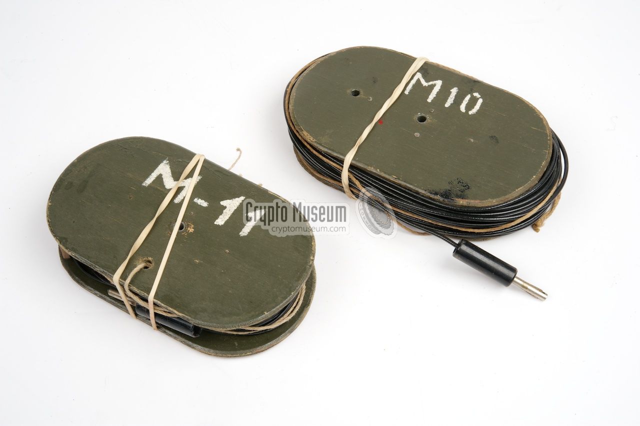
The antenna basically consists of two wires of 20 meters each. Depending on
the frequency in use, the wires can be adjusted at 4 different lengths.
When not in use, each wire is stored on a spool that is stored with the radio
in the storage container.
The manual gives clear instructions on how to setup
and use the antenna. With aid of a separate
rope and two throwing weighs, the
wires are effectively used as a dipole.
|
|
|
The X-version of the Kyynel M-10 (i.e. the M-10X) can be operated with a
standard crystal of the era, operating at the fundemental frequency or the
3rd overtone. The crystal is inserted in an extra socket on one of the side
panels.
The problem with a standard crystal however, is that the radio doesn't fit
the storage container whilst the crystal is inserted into the socket. For this
reason, an adapted crystal shape (Kide in Finnish) was produced
by T.I. Leiviskä. It is shown in the image on the right.
Crypto Museum is
currently looking for this type of crystal.
|
|
|
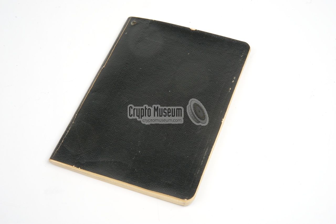
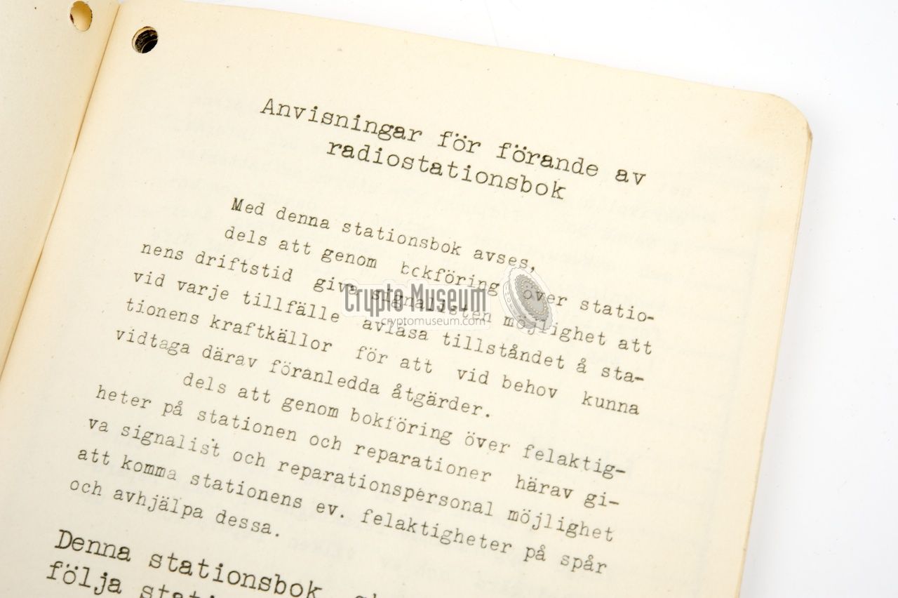
A small booklet with clear instructions on how to set up a working radio
station, was supplied with the M-10. The image on the right shows the booklet
that came with the Swedish version of the M-10X.
It contains a checklist, examples for setting up the antenna and
instructions on how to tune and operate the transceiver.
The rightmost page in the image shows how the LT and HT batteries are
connected to the radio. Click to enlarge.
|
|
|
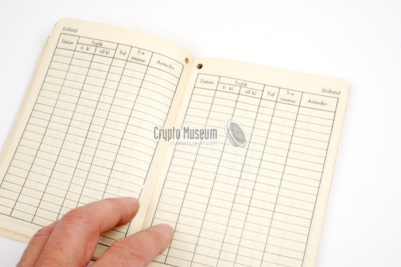
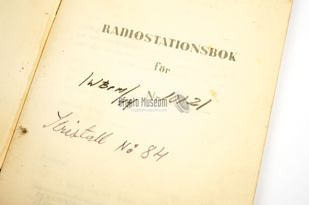
Each M-10 radio came with a small maintenance booklet
- the passport -
that contained simple instructions
and allowed modifications and other
changes to be logged in a table.
It also allowed radio traffic to be logged (journal).
The image on the right shows the first page of the passport, showing
the model and serial number of the radio and the number of the supplied crystal.
More images below.
|
|
|
|
The M-10 was manufactured by Army Depot Company Munkkiniemi from late
1942 onwards [1].
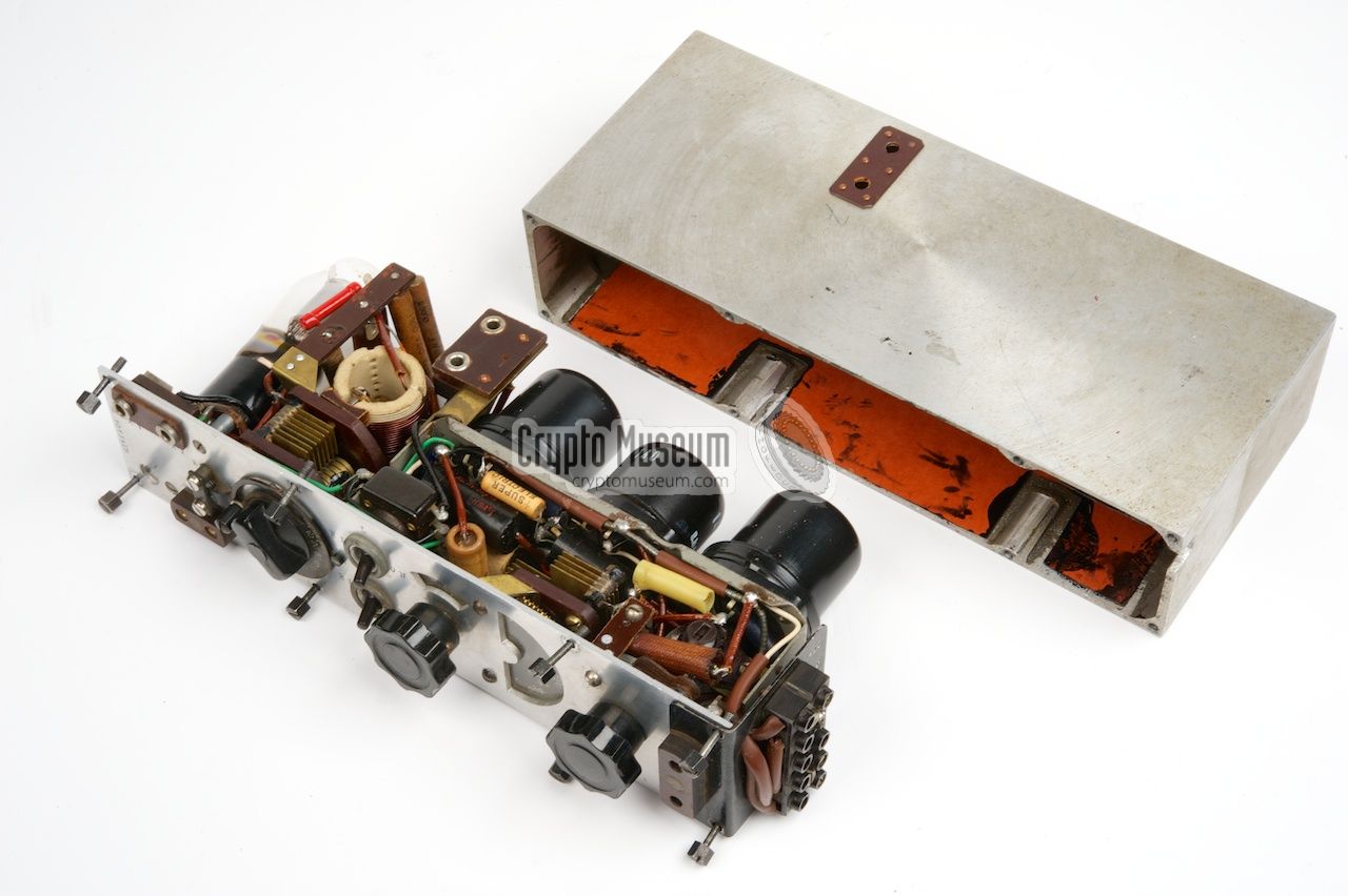
It is housed in a die-cast aluminium case - an idea of Holger Jalander -
that can easily be opened by releasing eight hex-bolts at the edges
of the control panel and lifting out the interior.
|
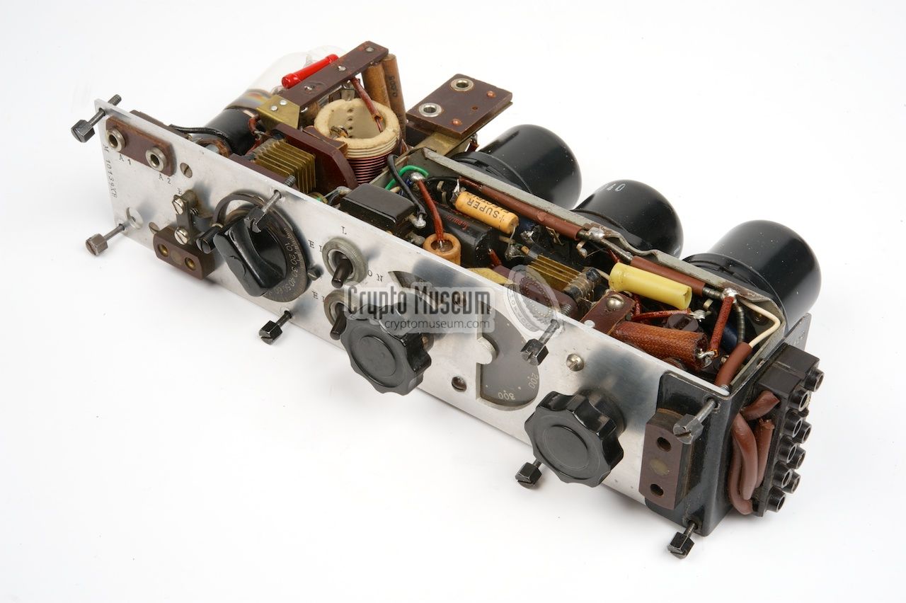
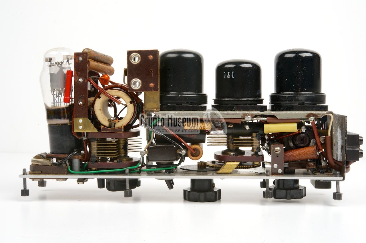
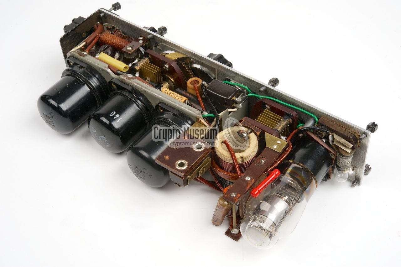
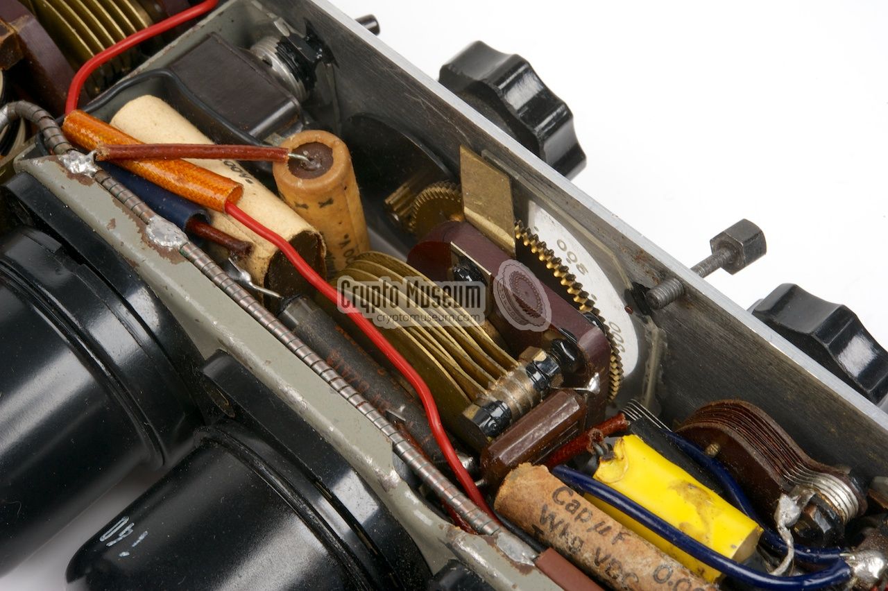
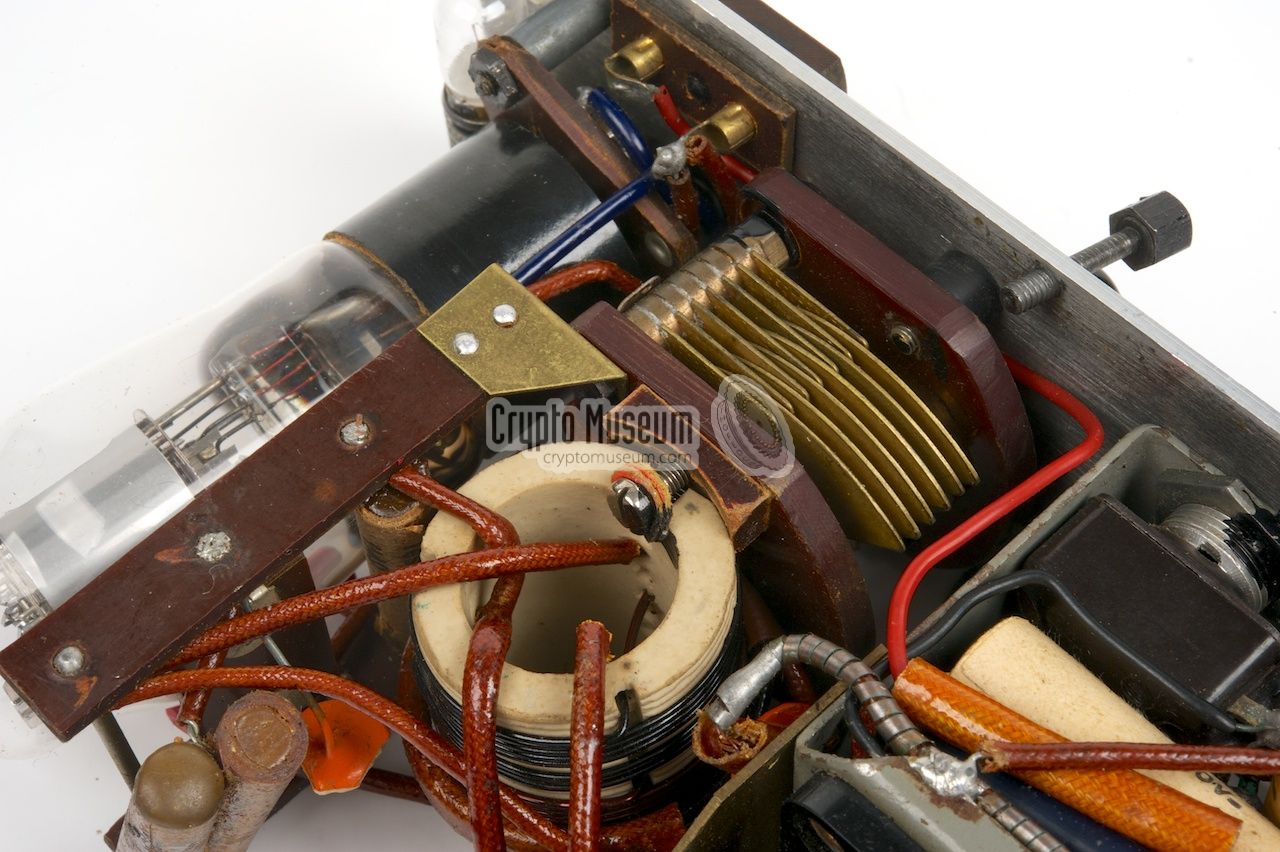
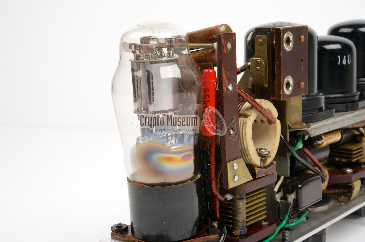
The image on the right shows the interior of the M-10X. The radio is well
built, with the three valves of the receiver
(2 x DF11 and DDD1) mounted next to each other.
The transmitter valve (DLL21)
is located at the other end.
The radio is powered by two voltages: 1.5V for the filaments (LT) and 120V
for the rest of the circuitry (HT). The 120V voltage was supplied by a large
rectangular HT battery and the 1.5V was supplied by two large cylindrical
batteries. All three batteries were located in a
cardboard case that
was bolted to the bottom of the radio set.
|
|
|
|
The batteries were connected to the black contact strip at the right side
of the radio by means of four wires.
The instruction manual
shows how the batteries were installed.
Early versions of the radio were stored in a
cardboard carrying case,
which was later replaced by a metal container.
|
Since Kyynel radios are so difficult to find, some collectors in Finland
have set up a project to build a good looking and operational replica.
If you are interested, check out their website:
➤ Kyynel replica
|
Below is the circuit diagram of the transmitter if the M-10, which is
built around a Tungsram DLL21 double-pentode valve that is used in
push-pull configuration. The circuit is based on the Kyynel M5 transmitter,
but has a connection for the antenna input of the receiver.
The image below shows the circuit diagram of the transmitter of the M-10X.
Like in the M-10, the transmitter is built around a DLL21 double-pentode
valve, but contrary to the M-10, the two halves of the pendode are
used connected in parallel rather than in push-pull configuration.
At the top right are the antenna sockets (A1/A2). In receive mode, A2 is
connected to ground. When the antenna is inserted half-way into socket A1,
the lamp can be used as a tuning indicator. When the plug is fully inserted,
the lamp is shorted. Switch S1(A/B) is shown in receive mode.
Note that the +120V anode voltage (HT) is switched directly by the morse key,
which should be connected at the bottom left. The transmitter can be used in
free-running mode, in which case L3 and L4 are used as a feedback loop, which
is connected to g1/1 and g1/2 of the DLL21 valve. When inserting a crystal
into the socket, switch S3 is engaged, which replaces L4 by the crystal.
The diagram above shows the circuit diagram of the receiver, which is built
around two DF11 valves and one DDD11. The first DF11 is used as an aperiodic
RF amplifier. At the center is the second DF11, which is used as a
regenerator/detector.The circuit is very similar to that of
the later M-11, but uses a potentiometer (P1) for controlling the
reaction, rather than a variable capacitor.
At the far right is the audio (AF) amplifier, built around
a DDD11 double-triode.
|
The DLL21 is a double pentode that is the only valve (tube) that is used in
the transmitter.
It is similar to the DLL2T that was used in the
German SE-109/3 spy radio set
of the era, albeit in a larger enclosure and easier to obtain.
In the M-10 the two halves of this valve are used in a push-pull configuration,
but in the M-11 they are simply connected in parallel (just like in the M-10X).
|
The DF11 is a black metal valve (Stahlröhre), first made in 1940 by
Telefunken, of which two are used here.
It is a directly heated Penthode that
is suitable for RF, IF and AF applications.
It has an LT voltage of 1.2V and a typical Anode voltage of 90V.
Below is the pinout of the DF11.
Note that the unused terminals (marked n.c.),
may be used as a mounting hub for other components.
➤ DF11 datasheet
|
DDD11 was a metal double-triode valve (German: Stahlröhre),
first made in 1940 by Telefunken.
It was used during and after WWII, typically in the AF section of
a receiver.
➤ DDD11 datasheet
|
- Storage container
- Kyynel M-10
- Morse key
- Headphones
- Tuning chart
- Operating instructions
- Passport (maintenance booklet)
- Antenna wires (2)
- Antenna rope
- Lead weight (2)
- Screwdriver
- Bag with spare components
|
|
We are currently looking for the following items for our Kyynel radio:
|
- Original 'low profile' quarz crystal
- Frequency/antenna tuning table
|
TX frequency range 3800 - 4800 kHz (79 - 63 m) RX frequency range 3600 - 4800 kHz (scale 1-300) HT voltage 120 V DC LT voltage 1.5V RX anode current 7 mA TX anode current 28 mA Filament current 100 mA TX power output 0.5 - 1 W Weight 5.6 kg
|
All Kyynel radio sets have their serial number engraved in the front panel,
and commonly also in one of the sides. The diagram below shows how the
serial number is constructed. It consists of a model number, a serial
number and (optionally) one or more suffixes.
|
M10 139 XB Crypto Museum 1
|
- User manual 1W Br m/44 (Swedish)
Sweden, December 1945.
- Original maintenance passport
Sweden, 1947.
- DF11 datasheet
Telefunken, 1 December 1941.
- DDD11 datasheet
Telefunken, 1 December 1941.
|
|
|
|
Any links shown in red are currently unavailable.
If you like the information on this website, why not make a donation?
© Crypto Museum. Created: Thursday 27 September 2012. Last changed: Wednesday, 05 November 2025 - 12:06 CET.
|
 |

|
|
|


![Image copyright Antero Tanninen [2]](img/Kyynel_kide_1_large.jpg)


![Image copyright Antero Tanninen [2]](img/Kyynel_kide_2_large.jpg)


![Original Kyynel M10X crystals. Photograph kindly supplied by Antero Tanninen [2].](img/Kyynel_kide_1_thumb.jpg "image # Kyynel_kide_1_large.jpg")
![Original Kyynel M10X crystals. Photograph kindly supplied by Antero Tanninen [2].](img/Kyynel_kide_2_thumb.jpg "image # Kyynel_kide_2_large.jpg")