|
|
|
|
|

|
|
Austria Cold War SBO ← BE-20/2
Spy radio set
BE 20/3 was a three-piece short-wave (SW)
spy radio set,
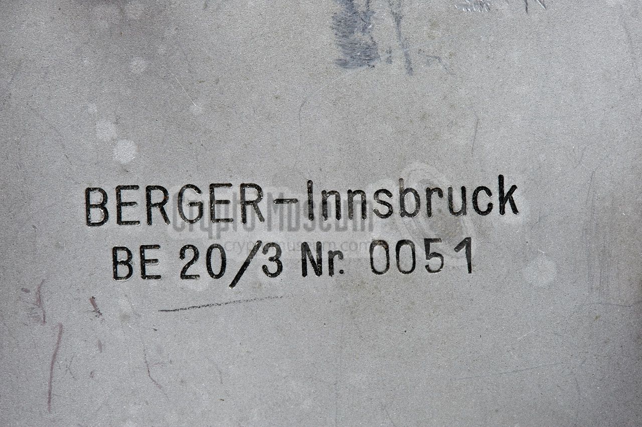
built around 1952 by Dr. Hermann Berger
in Innsbruck (Tirol, Austria). The device was supplied to several customers,
including the Austrian Army, the armies of the occupying forces 1
and the state security services.
It was also used for a
secret Austrian Stay-Behind network
that would be activated in case of problems with the
Soviet Union.
The device is nearly identical to the
BE-20/2 that is also known as
Poste Cunzi.
|
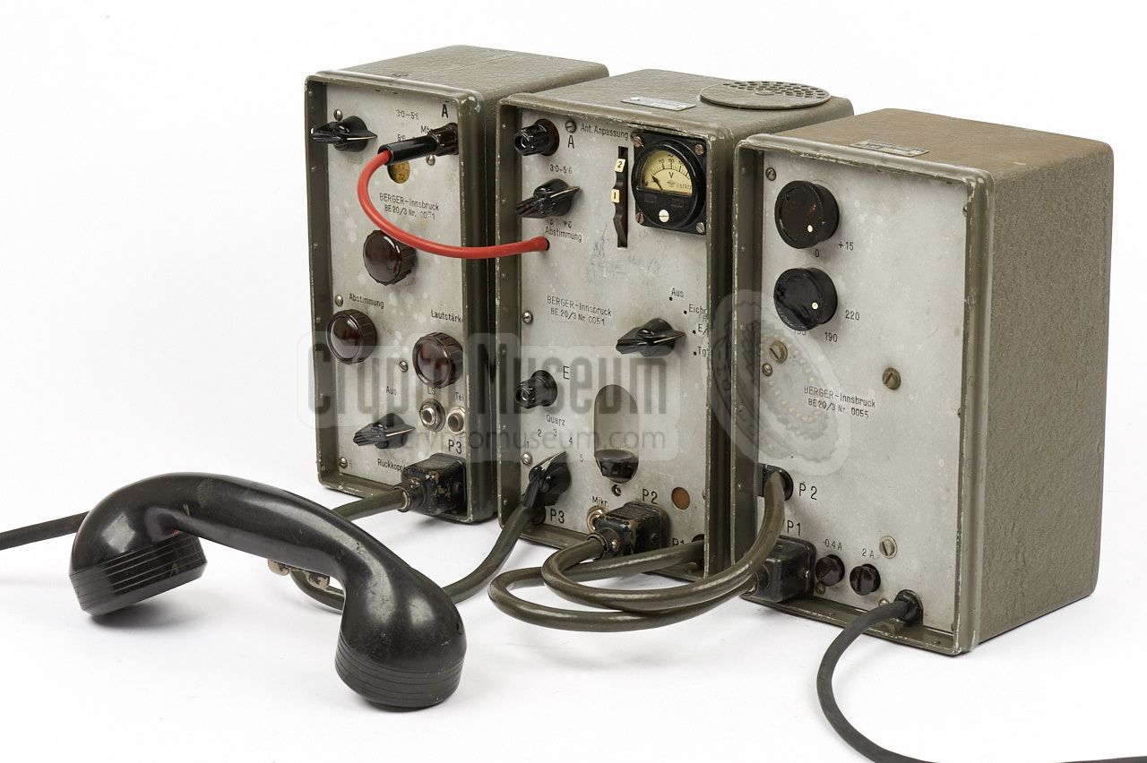
The radio set consists of three similar-size metal enclosures, that contain
a power supply unit (PSU),
a transmitter (TX)
and a receiver (RX).
The units are connected by means of thick cables, with the transmitter
acting as the central hub.
The image on the right shows a typical Berger BE-20/3 station with (from left
to right) receiver, transmitter and PSU. The PSU is connected to the mains
voltage and has two voltage selectors for setting the appropriate AC voltage.
An American field telephone handset
TS-13-C with Y-cable is connected to the transmitter and to the receiver.
|
|
|
Compared to the BE-20/2, the cases are finished in dark green/grey
wrinkle paint rather than bright green. The front panels are
made of blank steel with (black) engraved German lettering, whereas the
front panels of the BE-20/2 were screen printed in French.
Furthermore, the receiver has an extra socket for connection of a speaker,
in addition to the socket for the handset.
From the serial numbers of the surviving samples, it is estimated that
a total of 100 units (BE-20/2 plus BE-20/3) were made.
In the mid-1950s, the BE-20 was succeeded by the American
RS-6.
➤ Other versions of the BE-20
|
-
Shortly after WWII,
Austria was occupied
by the United States, the Soviet
Union, the United Kingdom and France. It became fully independent again
on 12 May 1955. ➤ Wikipedia
|
The diagram below shows a complete BE-20/3 radio station with all cables
in place, but without the handset. The power supply unit (PSU) is at the
far right and should be connected to the AC mains, after the correct mains
voltage has been selected with the two voltage caroussels at the front.
The PSU is connected to the transmitter at the center via two thick
grey power cables.
The transmitter is at the center and acts as the central hub to which
the other two units are connected. The transmitter is intended for voice
transmissions in AM, but can also be used for CW (morse) in case of an
emergency. A suitable long wire antenna should be connected to the
antenna socket at the top left (A), and a suitable counterpoise to the
ground socket (E). The antenna can be tuned with the antenna machting
selector and the antenna tuning knob at the top.
The transmitter has five fixed channels, that are
determined by five (interal) crystals.
The receiver is at the left and gets its power from the transmitter,
via the thick grey cable at the bottom. Furthermore, it gets the
antenna signal from the transmitter via a short orange cable at the top.
The receiver is freely adjustable over the entire 3-9 MHz range, divided
over two bands.
A suitable telephone handset should be connected to the microphone socket
of the transmitter (MIC) and to the TEL output of the receiver.
Note that the receiver also has a speaker socket (LS).
|
- Grey/green wrinkle paint case
- Blank front panels, engraved in German
- Extra socket on receiver for speaker
- Better quality cables
- Serial numbers above 0050
|
|
Development of the BE-20 took place in the late 1940s. In 1948 the first
prototype, the BE-20/1, was supplied to the French Army for evaluation.
This resulted in an order for 100 complete sets, that were codenamed
Poste CUNZI, after the name of Berger's contact person
in the French Army [5].
The production version was designated BE-20/2
and was largely built from wartime (German) surplus parts,
completemented by components from Berger's own factory.
The 100 units were built between 1949 and 1952 [1].
BE-20/3 is a later version with the front panels in German.
|
The sets were used as part of a nation-wide underground communications
network for the secret
Austrian stay-behind organisation,
that would have been activated in case of problems with the
Soviet occupation forces (1945-1955).
The secret paramilitary organisation consisted of approx. 2500
agents, and had underground caches with weapons and equipment at
strategic places throughout the country, so that important infrastructure
was secured in case of a conflict.
One such location was Tauernkraftwerke AG 1 ,
a hydro power plant in Kaprun (Salsburg, Austria).
|
|
|
Tauernkraftwerke was an ambitious project to build a large dam to
control the water flow in one of the biggest lakes in Salzburg, and use
this hydropower to generate electric enery.
The project was started in 1938 under control of Nazi Germany and continued
under American control, with funding from the Marshall Plan,
once the war had come to an end. It was completed in 1955.
|
For communication between the various sites of the project, it was decided to
buy radio sets from Berger.
Berger's daughter Waltraud, vividly remembers the day on which the
entire family travelled up to Kaprun to demonstrate the BE-20
to the company's director. At the event, one unit fell off a trolley
and rolled over several times, but still worked after Berger had
retrieved it. Needless to say that the deal was secured [5].
The sets that were delivered to Tauernkraftwerke AG were tagged
with a special inventory number plate, as shown in the image on the right.
|
|
|
Although it is entirely possible that the BE-20 was indeed used for on-site
communication at the Kaprun hydropower plant, it doesn't really make sense,
as single-piece radios would have been far more suitable.
Furthermore, it seems unlikely that the government
(or actually the Western Allied Forces)
would have approved the use of secret devices
like the BE-20 for civil purposes.
It is far more likely that Tauernkraftwerke AG acted as a front for the
stay-behind organisation, in order to hide the actual customer from any
public records, and possibly also from Dr. Berger himself.
This would also explain why some
BE-20/2 Poste Cunzi units,
with French lettering, were found with the same Tauernkraftwerke AG
inventory number shield on top of their enclosures.
In addition to the stay-behind organisation, the BE-20/3 was also
supplied to other customers, including the
B-Gendarmerie 3 , the Ministry of the Interior (Innenministerium)
and some of the Western occupation forces. For the French occupation
force, the BE-20/2 (with French front panels) was made.
It is currently unknown how many BE-20 units were manufactured, but given
the serial numbers of the surviving samples, it seems likely that
this was no more than 100 units.
➤ More about the Austrian stay-behind organisation
|
 |
-
Tauernkraftwerke AG is currently known as Austrian HydroPower AG.
-
A Berger BE-20/2 that was tagged Tauernkraftwerke, was put up for
auction in 2016 at auction house Hermann Historica in München (Germany).
-
The B-Gendarmerie was the predecessor of the Austrian Federal Army
(Österreichisches Bundesheer), similar to the German post-war
Bundesgrenzschutz (BGS). ➤ Wikipedia
|
In some cases, the BE-30/3 was supplied in a wooden transport case,
hence the name Funkkoffer BE-20 (radio suitcase BE-20) [4].
The original transport case is shown in the image on the right [3].
It contains three compartments for the individual units,
with a wider compartment at the top for the handset,
the wire antennas and any cables. The hinged front cover can be used
as a writing table. When closed,
it shows the Berger company logo
[3].
|
|
|
The PSU is the heaviest part of the three-piece radio set, mainly because
it houses a large AC transformer with many taps, allowing it to be used
on a wide variety of AC mains voltages, between 95 and 235 V. The desired voltage
is selected with two plug-in power caroussels.
The PSU is connected to the transmitter via two thick grey cables: one running
from the PSU to the transmitter and the other one running from the transmitter
to the PSU. Both cables have to be in place before the PSU is enabled.
|
|
|
The transmitter acts as the central hub of the radio set and has three
fixed wires for connection to the PSU and the receiver. The transmitter is
crystal-operated and is suitable for the entire 3 - 9 MHz frequency range.
Power is supplied by the PSU via two thick grey cables each with a 6-pin LIST
plug at the end: one from the PSU to the transmitter, and one from the
transmitter to the PSU. An external wire antenna should be connected to the
socket marked A at the top left. A short orange wire distributes
the antenna signal to the receiver.
|
|
|
The receiver has a Variable Frequency Oscillator (VFO) and can be adjusted
freely over the entire 3 - 9 MHz frequency range, divided over two bands
that span 3 - 5.6 MHz and 5.6 - 9 MHz respectively. It has a sensitivity of
1µV in CW (morse) and 2µV in AM (phone).
Power is supplied by the transmitter via a 6-pin LIST plug. The antenna signal
is also shared with the transmitter and is supplied via an orange rubber
antenna wire that is fixed to the body of the transmitter.
Audio output is delevered to a 6.3 mm jack socket.
|
|
|
For speech (phone), a TS-13-F handset was used, as built
by the American Microphone Company.
It has a carbon microphone and was also used with some popular WWII equipment.
The handset has a Y-shaped cable with a PL55 and a PL68 plug at the ends.
A butterfly-type PTT switch in present on the inside of the grip.
Note that the prototype BE-20/1 only works with the E-version of this
handset, as it is the only one that has a 11315-A dynamic 1 microphone.
|
|
|
-
The TS-13-E is also used with the BC-1000 radio and the EE-8B field phone.
All other versions of the handset have a carbon microphone and are
suitable for the BE-20/2 production variant.
|
In order to protect the units agains dust and moist, some radio sets were
supplied with bulged metal covers that could be fitted over the front panels.
The covers could be fastened with a canvas strap.
The image on the right shows two covers, one for the PSU (Al) and one for
the transmitter (E) as they were found with a surviving BE-20/2 [3].
|
|
|
|
Each of the three units is housed in a strong metal enclosure that is
finished in a grey/green wrinkle paint camouflage colour. The interior
of unit can be accessed by removing one or two screws at the rear,
after which the case shell can be removed. This may needs some force.
|
|
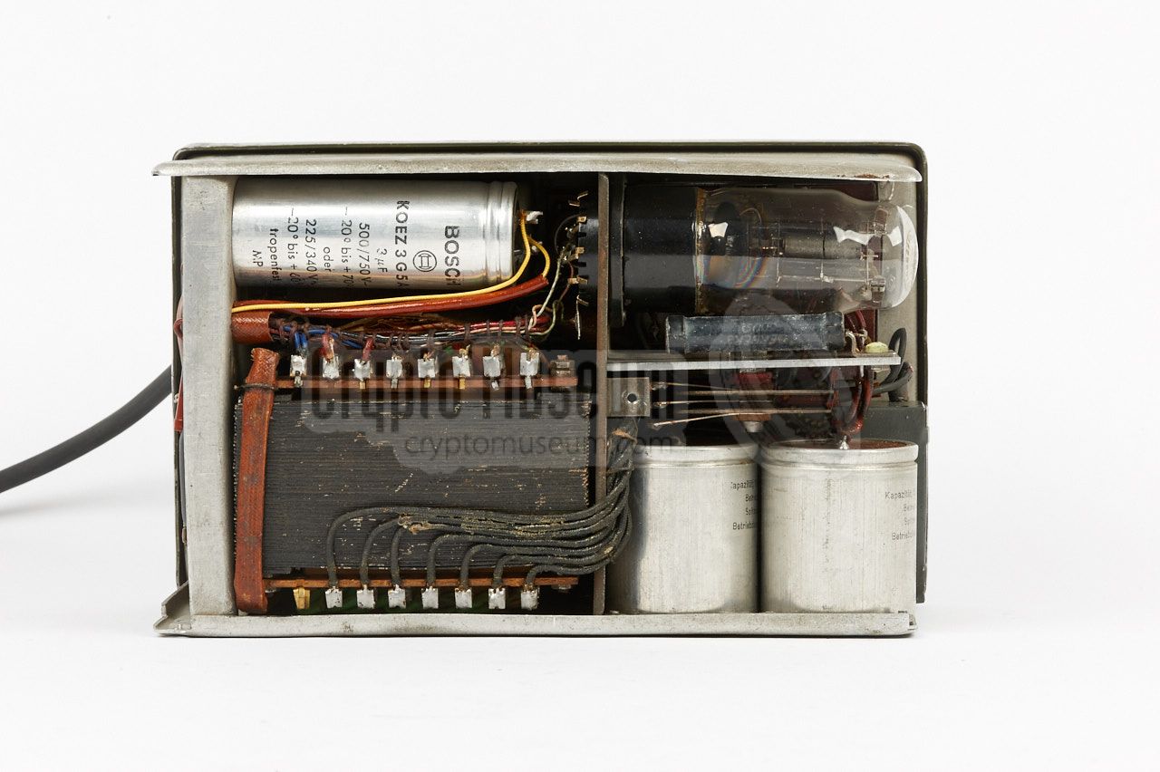
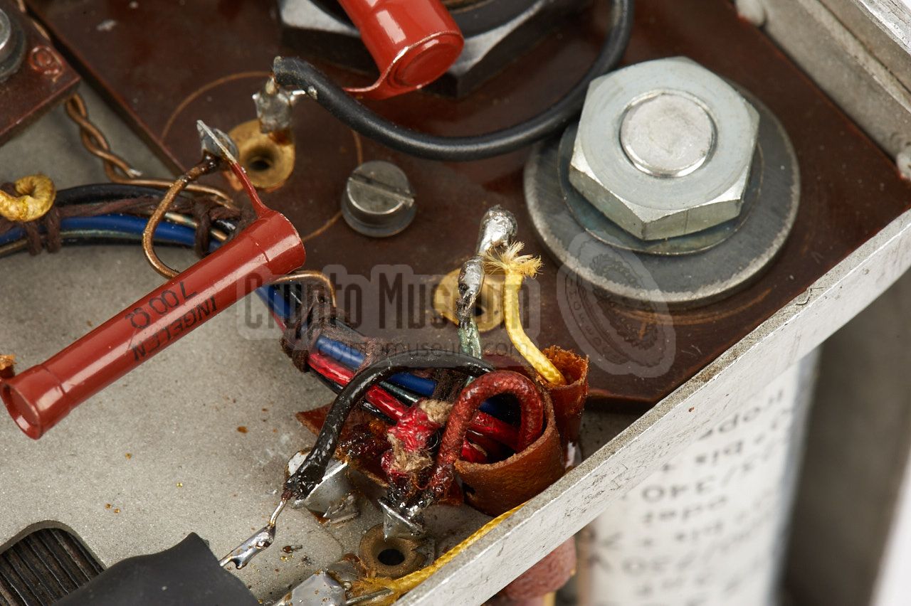
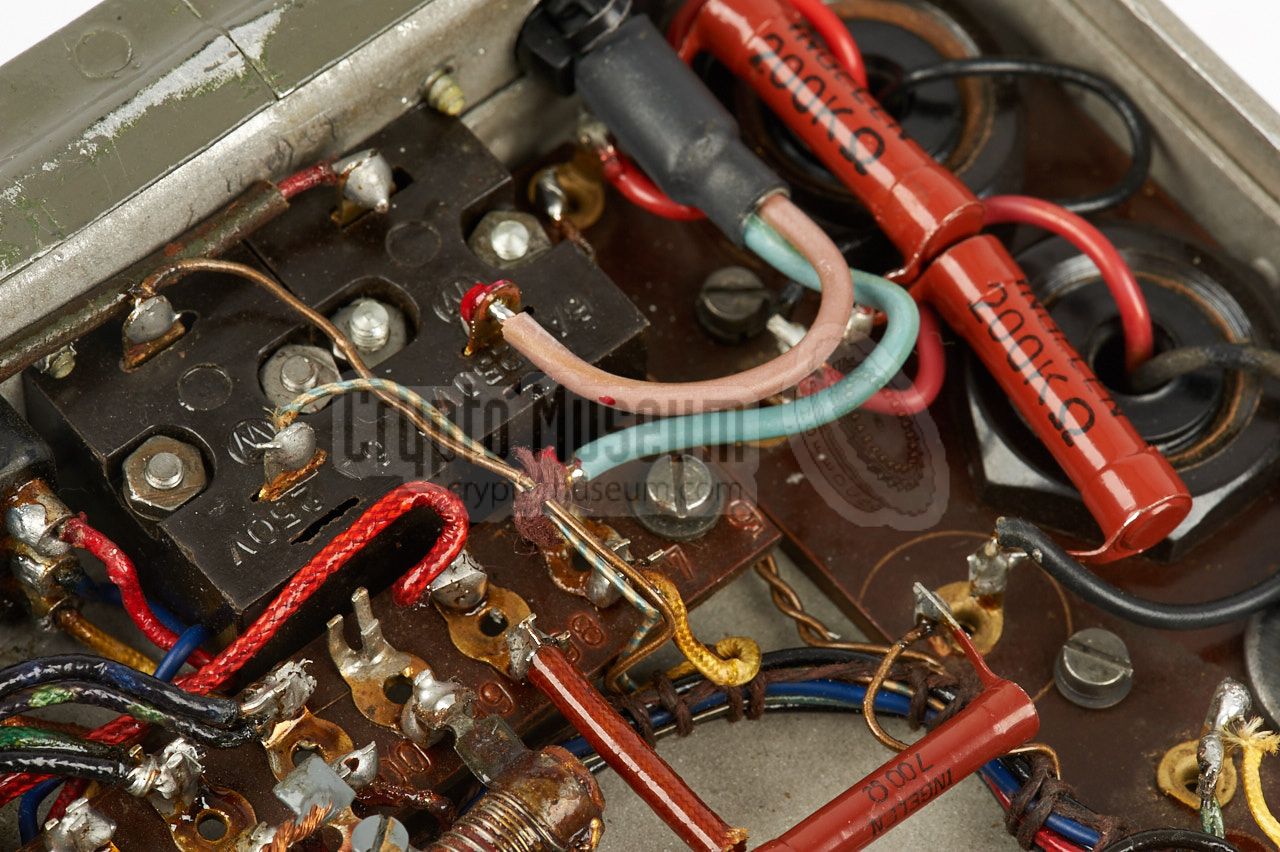
The power supply unit (PSU) is very heavy, as it contains a large
conventional transformer with many taps, that takes up about one-third
of the space. The rest of the unit is taken by a rectifier valve, several
electrolytic capacitors, selenium rectifier and some passive
components.
|
If the unit has not been powered up for several years, the capacitors
may have dried out, and may have to be reformed first. Check the chapter Restoration to see how capacitors are reformed.
Operation of the PSU is pretty straightforward. At the heart is a large
conventional transformer of which the primary side is suitable for connection
to a wide range of mains voltages between 95V and 235V.
The secondary side produces two DC voltages: 6V for the filaments and
650V for the anode voltage of the transmitter. In addition,
the raw 6V AC voltage is also available on socket P1.
|
|
|
|
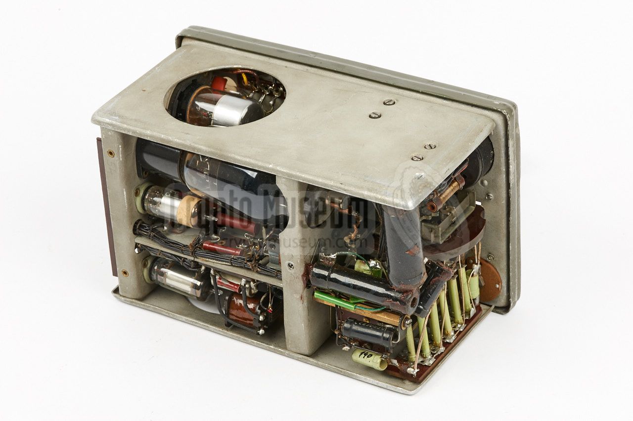
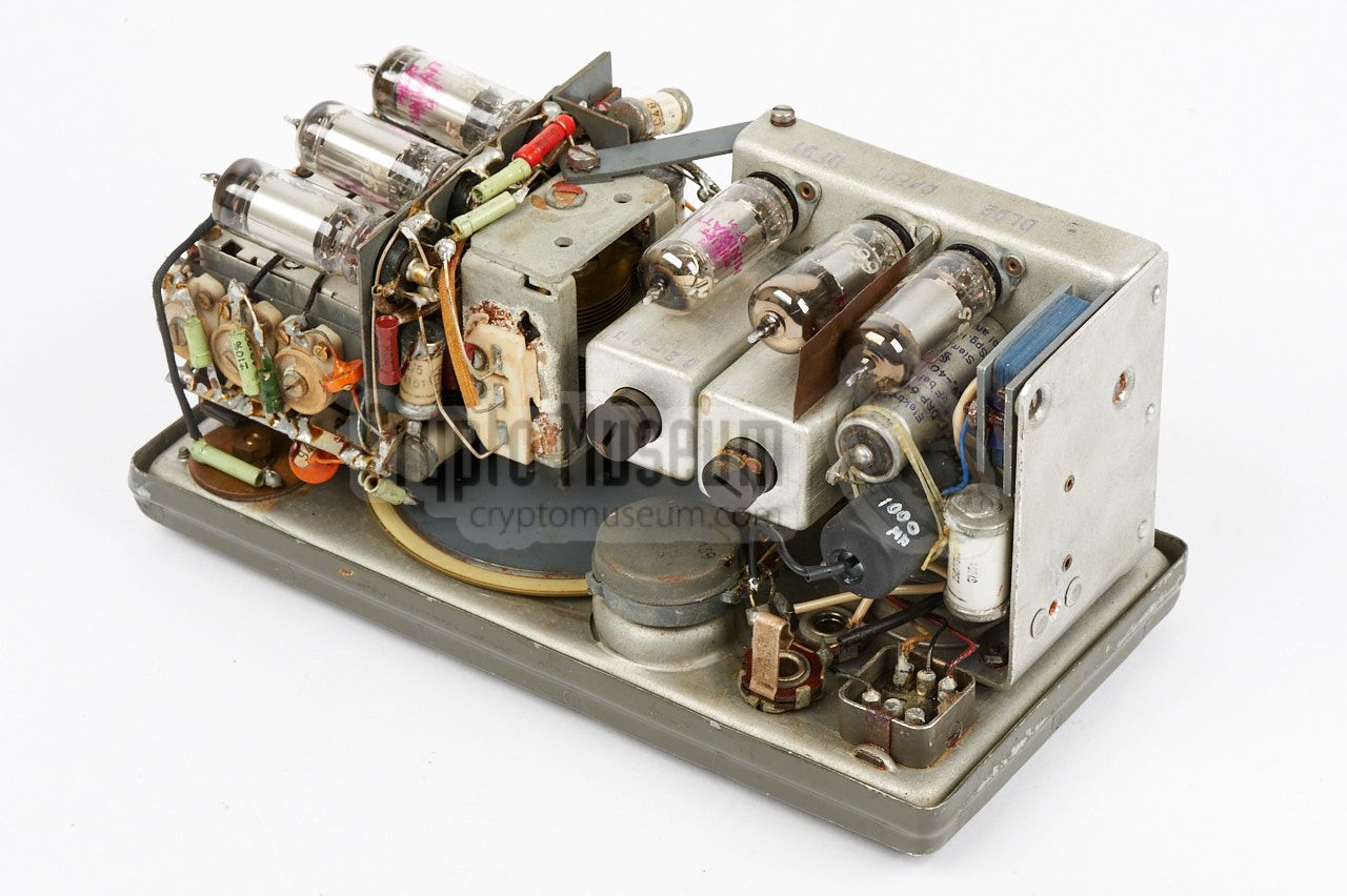
The transmitter is slightly wider than the other two units. Its interior
can be accessed by removing a single screw from the rear of the case,
after which the grey case shell can be taken off. Note that this may require
some force, as the shell might be binding to the front panel.
|
All parts are mounted onto a metal frame that in turn is mounted to the
front panel. The frame consists of two horizontal planes, the lowest of
which hold the valves. For servicing, the valves can be accessed from the
rear of the unit, or through a large circular hole in the side panel.
A similar large circular hole in the opposite side panel, gives access
to five crystal sockets that are needed for the five front panel selectable
channels.
|
|
|
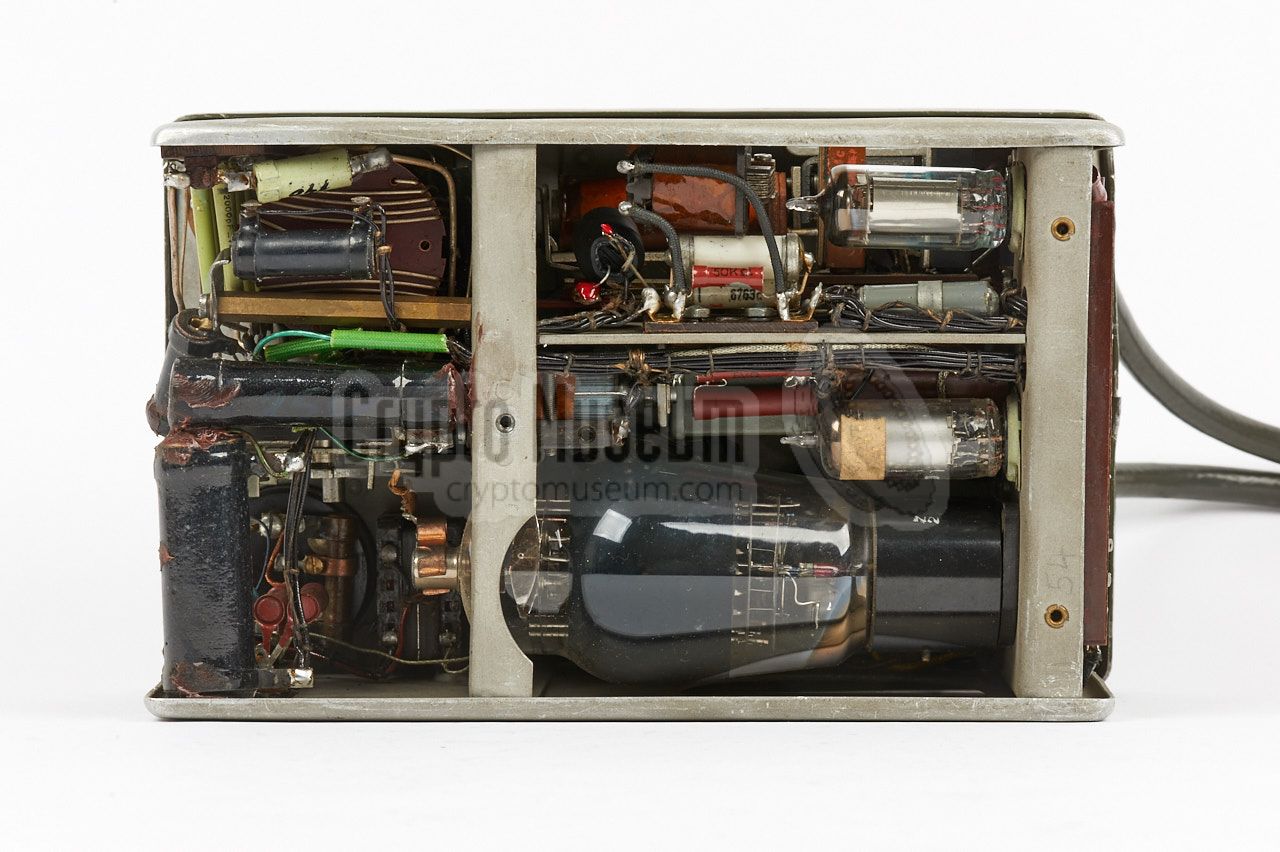
The receiver is highly compact and consists of no less than 6 valves.
At the center is a large adjustable capacitor that is attached to the
tuning gear.
The image on the right shows the interior of a typical BE-20/3 receiver.
Further images are available below.
|
|
|
|
Bringing an old Berger BE-20/3 back to life may not be straightforward,
as some components may have aged. If the device is in an unknown
state, it would be wise not to power it up directly. Instead open
the units and inspect them thoroughly before continuing. Especially the
electrolytic capacitors may have to be reformed.
If that doesn't work, you may even have to replace them.
|
The mains cable is made of rubber and may have become brittle
over the years. It would be wise to replace the power cable before
turning the unit ON, even if the existing cable looks alright.
When working on the PSU, it may be useful to install a dummy connector
in socket P1, with a loop wire between pins 3 and 4, in order to
enable the PSU. An example of a suitable dummy plug is shown in the image on
the right. Always be careful, as this plug carries high-voltages, including
the AC mains and 700V DC. The full
pinout of socket P1
is specified below.
|
|
|
One of the first things to check is the state of the capacitors inside
the PSU. If the device has not been powered for several years, it is
very likely that the capacitors have dried out and will need reforming.
This is best done
by connecting the PSU to the mains via a so-called VARIAC. Set the dial
to 50V AC and leave it at that voltage for half an hour, whilst monitoring
the output voltage between pins 1 and 6 of socket P1. Also check whether
any capacitors are overheating.
If all goes well, increase the voltage on the dial of the VARIAC
gradually in steps of 20V and wait each time until the output voltage on
pin 6 of P1 is stable (when it no longer increases slowly). If this is
the case, wait a little longer and then move on to the next step. Once
the nominal AC voltage is reached (220V), the unloaded DC output
on pin 6 of P1 should be around 700V.
|
|
For connection between the three units of the BE-20/3,
6-pin LIST connectors were used from post-war Luftwaffe (Air Force)
surplus stock. Sockets and plugs are available in male and female variants
and a notch is present to prevent a plug from being inserted the wrong
way around.
|
|
This is a cable that runs from the transmitter (TX) to the power supply
unit (PSU). At the TX-end it is fixed. At the PSU-end is a 6-pin male
LIST plug that mates with socket P1 on the PSU. The diagram below shows
the pinout of the socket P1 on the PSU, when looking into the socket.
|
- Ground (0V)
- 6V AC
- 220V ~ → to transmitter
- 220V ~ ← from transmitter
- LT +6V DC
- HT +650V DC
|
|
|
P2 is a cable that runs from the PSU to the transmitter. At the PSU-end
it is fixed. At the TX-end is a 6-pin female LIST plug that mates with
the male P2 socket on the transmitter. The diagram below shows the pinout
of male socket P2 on the transmitter when looking into the socket.
|
- ?
- Loop to 6 (in the plug)
- ?
- ?
- ?
- Loop to 2 (in the plug)
|
|
|
P3 is a cable that runs from the transmitter (TX) to the receiver (RX).
At the TX-end it is fixed. At the RX-end is a 6-pin female LIST plug that
mates with the male P3 socket on the receiver. This cable 1 provides power
to the receiver. The diagram below shows the pinout of socket P3 on
the body of the receiver when looking into the socket.
|
- ?
- ?
- Linked to 1 (in the plug)
- ?
- ?
- ?
|
|
-
The antenna signal is supplied by the transmitter via a separate (orange)
wire with a banana-plug at the end. This plug should be inserted into the
socket marked ANTENNA on the receiver.
|
Power 95 - 220V AC, generator 6 - 45V, 6V or 12V DC with inverter
|
Frequency 3 - 5.6 MHz, 5.6 - 9 MHz Sensitivity 2µV (phone), 1µV (CW)
|
Modulation Phone (A3), Telegraphy (A1, CW) Frequency 3 - 9 MHz (crystal) Output 6 Watt (phone), 18 Watt (CW)
|
|
Originally, transmitter, receiver and PSU all had the same serial
numbers, but the units often got swapped in later years.
So far, only two complete BE-20/3 radio sets are known.
The following serial numbers have been taken from the surviving devices.
|
0051 Crypto Museum, Netherlands 1 0052 Günter Hütter, Austria 1 0054 Günter Hütter, Austria 1 0055 Crypto Museum, Netherlands 1
|
-
Note that this circuit diagram is for the BE-20/1 prototype and does
not fully match the circuit of the production units (BE-20/3). Ignore the
connections of the 6-pin LIST connectors as they are wrong.
Documents kindly supplied by Günter Hütter [3].
|
|
|
|
Any links shown in red are currently unavailable.
If you like the information on this website, why not make a donation?
© Crypto Museum. Created: Sunday 18 December 2016. Last changed: Thursday, 15 December 2022 - 17:03 CET.
|
|

|
|
|


![Hydropower lake at Kaprun. Image via Wikipedia [6].](img/kaprun.jpg)


![Wooden transport case (German: Koffer). Copyright Günter Hütter [3].](img/gh_case_1.jpg)


![Two front panel covers. Copyright Günter Hütter [3].](img/gh_lid_1.jpg)
![Wooden transport case. Copyright Günter Hütter [3].](img/gh_case_2_thumb.jpg "image # gh_case_2.jpg")
![Wooden transport case. Copyright Günter Hütter [3].](img/gh_case_3_thumb.jpg "image # gh_case_3.jpg")
![Wooden transport case. Copyright Günter Hütter [3].](img/gh_case_4_thumb.jpg "image # gh_case_4.jpg")
![Front panel covers (inside). Copyright Günter Hütter [3].](img/gh_lid_2_thumb.jpg "image # gh_lid_2.jpg")
![Wooden transport case. Copyright Günter Hütter [3].](img/gh_case_2.jpg)
![Wooden transport case. Copyright Günter Hütter [3].](img/gh_case_3.jpg)
![Wooden transport case. Copyright Günter Hütter [3].](img/gh_case_4.jpg)
![Front panel covers (inside). Copyright Günter Hütter [3].](img/gh_lid_2.jpg)