|
|
|
|
|

|
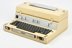
Full-duplex voice and data transceiver
The Radiodata SEM F-221 sometimes identified as the RDN-221 1 , was a
full-duplex radio
for voice and data traffic, introduced in 1987 by
RDN Radiodata GmbH in Dehlewitz (Germany), for use by the German public safety
services (BOS). 2 The radio operates in the 2 m radio band and is in fact
a modified version of the SE-221 radio of 1981 made by
Standard Electric Lorenz (SEL)
[1].
|
The radio set was developed especially for use in combination with the
Telefunken Telestar 121 mobile data terminal,
just like the Bosch KF-802 (FuG-8b/c)
that was used by some German
BOS services, such as the police and the fire brigade.
A complete system consisted of the Radiodata
SEM F-221-1620 GW51/D
transceiver – i.e. the modified SEL radio
– and the BG-217-5/FRP
remote control unit
[1].
The latter was basically a standard BG 217-4/5 unit,
of which the existing hardware and software had been modified by RDN,
to provide control over the extra features.
|
|
|
|
The sets were modified for full duplex data traffic on BOS channels
101 — 125. Although mainly used for sending text messages via the
Telestar terminal, it was also possible to place voice calls.
This feature was hardly used however, as there were no handheld radios
for these channels at the time.
Many RDN-221 sets were delivered to the Ministry of Internal Affairs
of the German County of Rheinland Pfalz during the course of 1987 and
1988. They were used until at least 2004 [1].
|
-
Although this name is officially incorrect, we are using it here as an
abbreviated form of the full name, which is simply too long and too
complicated:
SEM F-221-1620 GW51/D with BG-217-5/FRP.
-
BOS = Behörden und Organisationen mit Sicherheitsaufgaben
(Public Safety Organisations).
➤ More
|
All user interaction is via the clear control panel on the
modified BG-247 remote control unit, as shown in the diagram below.
It consists of 20 push-buttons, a clear liquid crystal display (LCD)
and 4 indicator lights. The global operation is controlled with the
buttons at the lower edge. The radio is turned ON and OFF with the
leftmost push-button (E/A). A channel can be selected by pressing the
(C) button followed by a 3-digit channel number (101-125).
Use (✱) for corrections.
Four indicator lights along the upper edge show the current state of
the radio. The first yellow LED is lit when the speaker is switched
ON. The second yellow LED blinks when a call is waiting to be answered.
The remaining LEDs are lit when the radio is receiving (red) or
transmitting (green).
The radio can send several tones for selective and non-selective calls,
activated by pressing the (R) button followed by one of
the number buttons (0-9). The following tones are implemented:
|
R1 1750 Hz continuous tone for repeater operation R2 2135 Hz continuous tone for repeater operation R3 Scan-Stop tone (initiates conversation with control center) R4 2800 Hz continuous tone (call all) R5 5-tone sequency (starts scanning at the control center)
|
|
If necessary, it is possible to select a different frequency band
or a different mode of operation, by using the (U/O) and (G/W)
buttons. The current selection is reflected in the
horizontal dashes in the rightmost position of the display.
(U/O) and (G/W) have the following meaning:
|
U Lower band (German: Unterband) O Upper band (German: Oberband) G Duplex (German: Gegensprechen) W Simplex (German: Wechselsprechen)
|
The diagram below shows the layout of the display (LCD).
At the far left is the subscriber number of the other party,
for outgoing calls. The number is entered via the numerical keypad,
after which the call is initiated by pressing the (Z) button.
The second groups shows the subscriber number of an incoming call.
The letter 'P' is shows when CTCSS is enabled (P = pilot tone).
The number group at the right represents the selected radio channel.
It is prefixed by the letter 'C', whilst the first '1' of the channel
number is omitted. In the example (C05) channel 105 is selected.
Two horizontal dashes at the far right of the display, indicate the
setting of the U/O (band) and G/W (mode) selectors. There settings
are usually pre-defined for the selected channel.
|
The device is based on the SE-221 (also known as the SEL-221),
a full-duplex radio for the 2-meter band, developed in 1981 by
Standard Electric Lorenz (SEL)
and in production from 1983 onwards.
The SEL-221 is based on the earlier FuG-9b 1 /FuG-9c 2
devices that operated on BOS channels 01—92.
SEL eventually solds its product line to
Bosch,
where the devices were produced for many years,
until Bosch sold its mobile radio portfolio to
Motorola in 1997.
Radiodata was a relatively small company which had a good and close
relationship with Bosch. In many cases they developed products for
markets that were too small for Bosch, some of which were even sold
under the Bosch brandname. When the German Government of the Country
of Rheinland Pfalz needed a new emergency system for their public
safety services, or BOS, (German: Katastrophenschutz, or KatS),
Radiodata was commissioned to develop the necessary equipment.
The SEL-221 (by now produced by Bosch) was used as the starting
point. It was heavily modified by Radiodata, who converted it for
use on the BOS channels 101—125, and added its own RDN data modem.
The existing control unit (German: Bediengerät, or BG) was modified
for the extra features. Furthermore, an interface was provided for
the Telefunken Telestar 121 data terminals.
The devices were delivered to the Ministry of Internal Affairs of
the County of Rheinland Pfalz, during the course of 1987 and 1988,
after which they were in service until approx. 2004.
The devices can be recognised by the blue RDN-logo on the front panel.
|
 |
-
The suffix 'b' indicates a standard device.
-
The suffix 'c' indicates a device with a special control unit,
with relay contact.
|
|
|
Transceiver
SEM F 221-1620 GW51/D
|
|
|
The transceiver is based on the SE-221 that was developed by
Standard Electric Lorenz (SEL)
in 1981 and produced from approx. 1983
onwards. Radiodata added its own RDN radio data modem and made
the radio suitable for full-duplex data.
The transceiver has a standard form factor, so that it fits
existing installations and mounting brackets. It does not have
any direct controls. Instead it is controlled by the external
BG-217 Bediengerät
(control unit) that is connected via
the 37-pin sub-D connector (DB37)
at the front.
|
|
|
|
|
Control unit
BG 217-5/FRP
|
|
|
All functions of the transceiver are controlled by the external
control unit shown in the image on the right. It is basically
a BG 217-4/5 of which the hardware and software have been
modified, resulting in the BG 217-5/FRP that has the same
form factor and fits in the existing space.
The hardware is modified for CTCSS use, and a 10-pin
socket is provided for connection of the standard handset.
The software was modified for CTCSS and selective tone
call (SELCALL), using a unique 5-tone sequence to address each
radio.
|
|
|
Especially for the so-called Katastrophenschutz (KatS) –
the regional emergency management system – the radios were
equipped with Telestar 121 data terminals made by Telefunken.
The image on the right shows a typical Telestar 121.
These terminals were also used by the German Federal Police, German
Customs (Zoll) and the Bundesgrenzschutz (BGS), for connection to the
nationwide INPOL information system. Telestar terminals were also used
by NATO.
➤ More information
|
|
|
The radio came with a full set of cables for connecting the transceiver
to the control unit, the control unit to the data terminal and –
for plain voice conversations – to the handset.
The image on the right shows the audio cable that connects the handset
– via the data terminal – to the control unit. By routing it via the
data terminal, the latter can be used to select between data and
voice traffic.
|
|
|
|
BG
|
|
Bediengerät
Control unit.
|
|
CTCSS
|
|
Continuous Tone Coded Squelch System
Continuous sub-audible audio tone, that is send with a voice transmission
in order to open the noise cancelling system (squelch) of the receiver at
the other end. Commonly used with transmissions via a repeating station (repeater). Also known as Pilot Tone (P).
|
|
G
|
|
Gegensprechen
Operation via repeater. In this case it means duplex operation.
|
|
O
|
|
Oberband
Upper frequency band.
|
|
SE
|
|
Sender/Empfänger
Transceiver (transmitter/receiver).
|
|
U
|
|
Unterband
Lower frequency band.
|
|
W
|
|
Wechselsprechen
Simplex operation.
|
-
Document kindly provided by Klaus Paffenholz [1].
|
|
|
|
Any links shown in red are currently unavailable.
If you like the information on this website, why not make a donation?
© Crypto Museum. Created: Friday 12 January 2018. Last changed: Monday, 15 January 2018 - 09:47 CET.
|
|

|
|
|