|
|
|
|
|

|
|
RX CIA Bugs SRR-5 →
VHF Surveillance Radio Receiver
SRR-4 is a compact mobile VHF surveillance receiver,
developed between 1956 and 1958 by the Technical Services Staff (TSS) 1
of the US Central Intelligence Agency (CIA)
in cooperation with the manufacturer Radio Receptor Co. Inc,
in New York (USA).
It covers 50 - 200 MHz in a single band and can demodulate
AM, FM, CW and modulated CW signals.
Although the receiver was intended for general communications applications,
it was typically used for intercept, surveillance, band monitoring,
direction finding and
in particular for the reception of
covert listening devices (bugs).
|
For actual (field) use, some additional items may be required, such as
batteries, headphones, and perhaps external recording equipment. The receiver
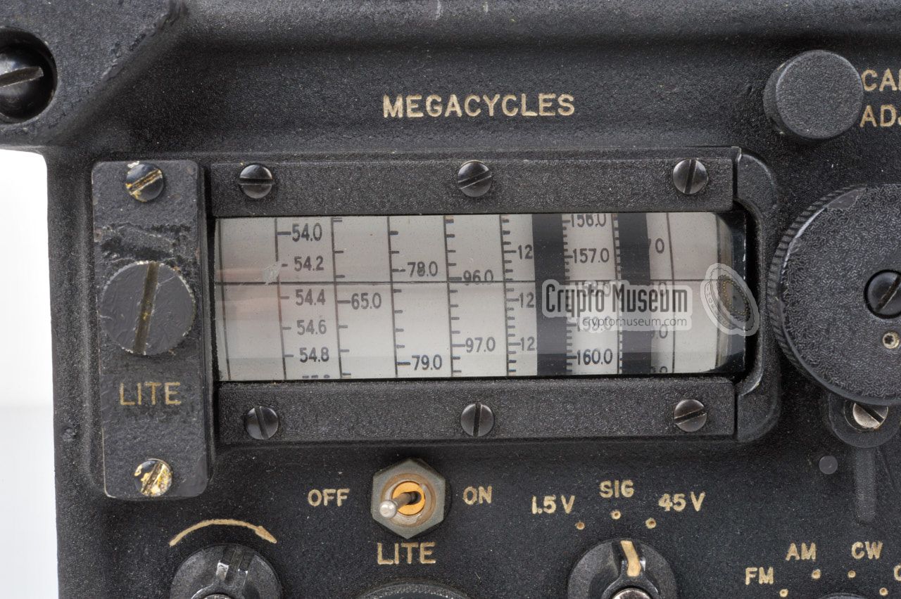
is continuously tunable over the entire 50 - 200 MHz frequency band,
and the tuning cursor of the drum-type frequency scale at the top left
can be calibrated by means of the built-in calibration oscillator
at 5 MHz intervals.
The design of the radio is based on the military
R-744 receiver which
covers a frequency range of 20 to 100 MHz and is housed in a nearly
identical enclosure.
The SRR-4 was succeeded in the early 1960s by the fully transistorized
SRR-5,
which offered an expanded frequency range of 50 to 400 MHz.
The receiver was also used by the Norwegian Stay-Behind Organisation
(SBO) [1].
|
 |
-
The Technical Services Staff (TSS) of the CIA was renamed
Technical Services Division (TSD) in February 1960, and
Office of Technical Service (OTS) in 1974 [3].
The SRR-4 is not completely developed from scratch by TSS/TSD,
but is based on the same design as the US Army Signal Corps
R-744 receiver.
|
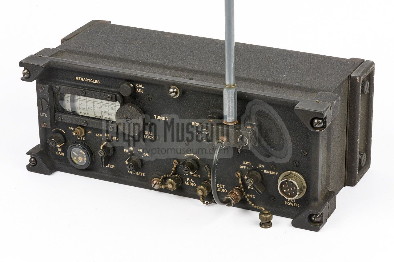
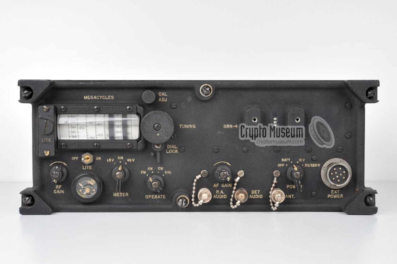
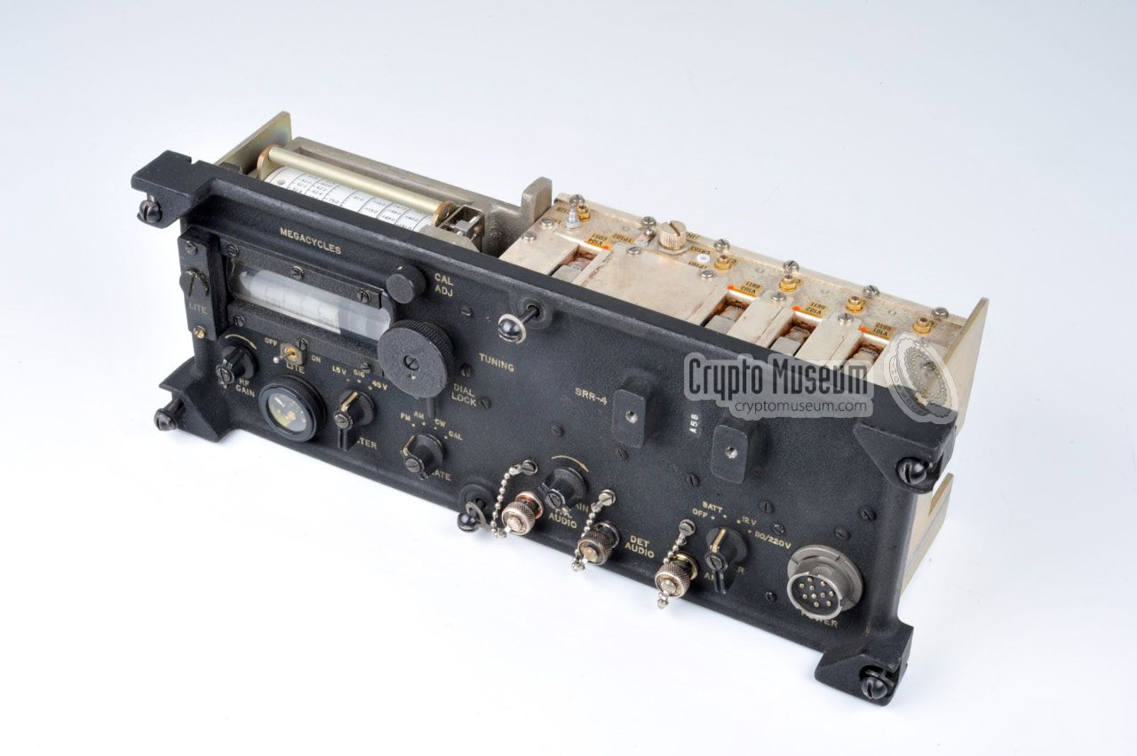
All controls and connections are located at the front panel of the SRR-4,
as shown in the diagram below. At the top left is the drum-type
frequency scale
that convers the entire 50-200 MHz frequency band. A bulged glass cover
provides some level of magnification, whilst a small lamp, mounted at the left,
illuminates the scale in the dark. The frequency is
adjusted with the large
knob to the right of the frequency scale and can be locked with a small lever
underneath it.
At the bottom center is a selector marked OPERATE. It is used to
select the modulation type (FM, AM or CW) or the built-in calibrator.
When enabled, the calibrator produces a signal at 5 MHz intervals (e.g.
120 MHz, 125 MHz, 130 MHz, etc.). The scale calibration knob, at the top
edge of the front panel, allows the horizontal hairline of the scale to be
adjusted to the nearest 5 MHz.
A suitable antenna should be connected to the ANT socket.
When the supplied telescopic antenna is used, it should be fitted to the
antenna mount at the top right.
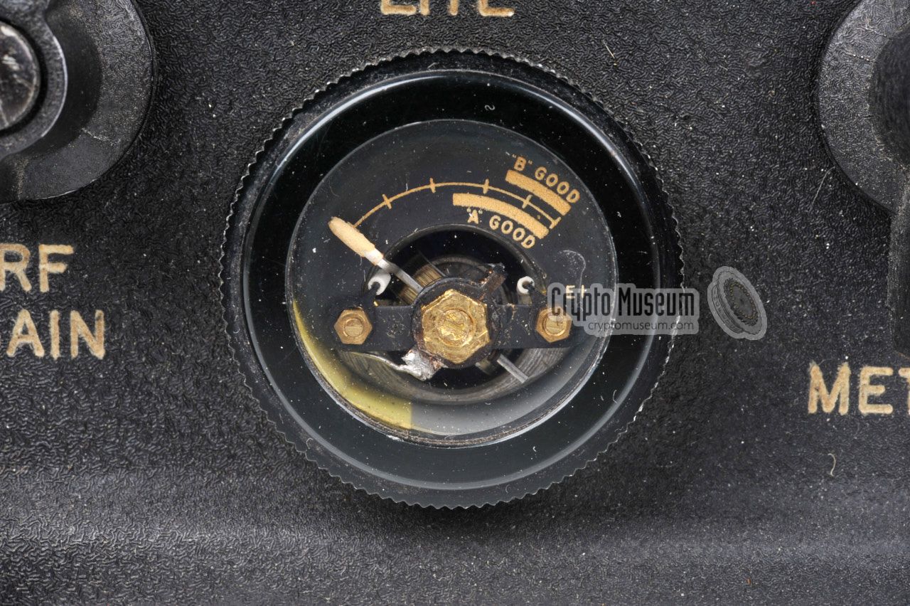
The S-meter at the bottom left shows
the signal strength of the received station. The meter can also be used
to test the internal batteries, by momentarily setting the
meter-function-switch to 1.5V (LT) or 45V (HT).
As the receiver does not have a built-in speaker, 600 ohms headphones
should be connected to the socket marked PA AUDIO and the AF GAIN knob
is used to adjust the volume.
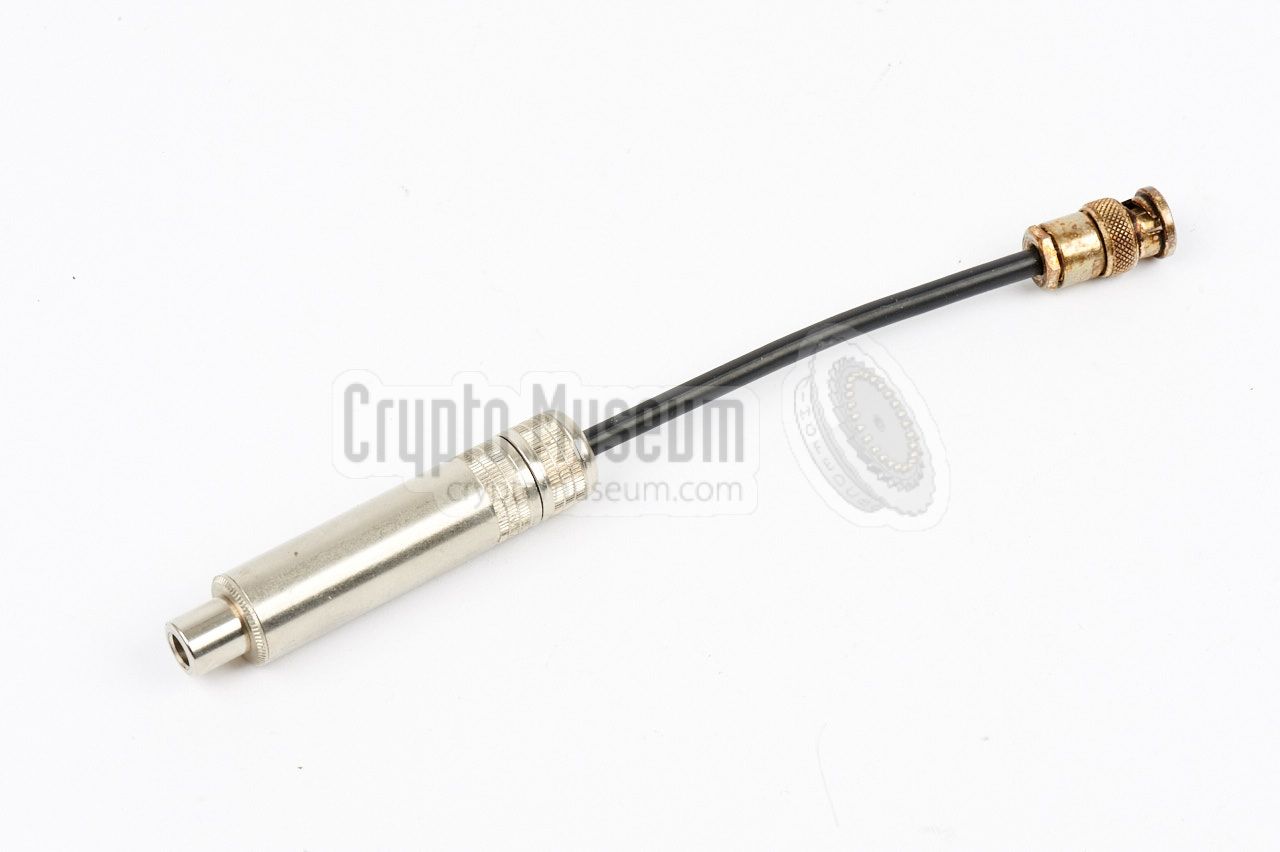
As the audio output is provided on a BNC-type socket, a special
conversion cable
is supplied for connection of a standard pair of
headphones, with a 6.3 mm jack.
Recording equipment (such as a tape or wire recorder) can be connected
to the socket marked DET AUDIO, which has a fixed audio level.
|
- VHF-L band — ASR-1
This version covers the lower VHF band from 20 to 100 MHz, and does
not have the name SRR-4 engraved on its front panel.
There are indications that this version might also have been known as ASR-1.
It is built around 12 valves (tubes) and has calibration points every 2 MHz.
The RF design is very similar to the
military R-744/PRR receiver.
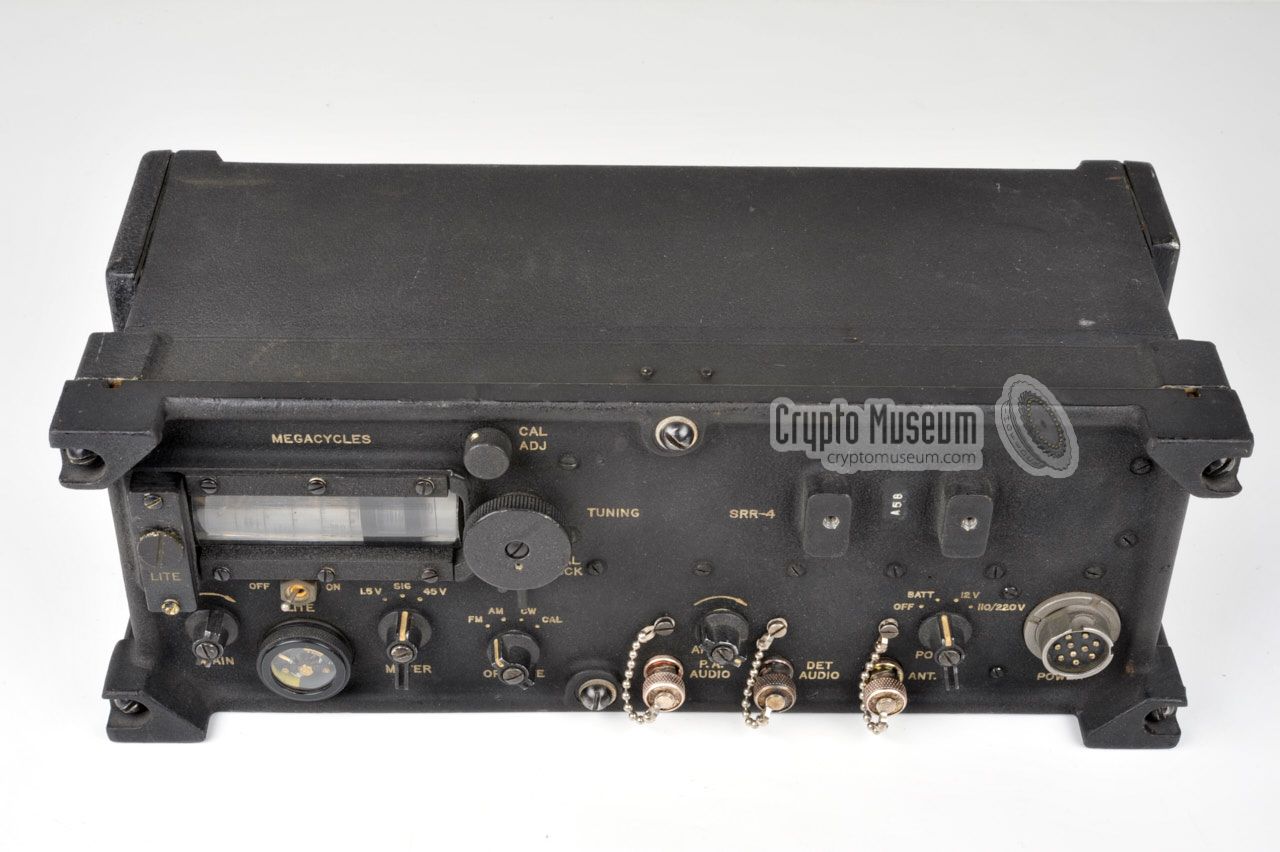
- VHF-H band — ASR-2, SRR-4
This version covers the higher VHF band from 50 to 200 MHz.
It is built around 12 valves (tubes) and has calibration points every 5 MHz.
It is possible that this version was initially known as ASR-2 and that at
some point it was renamed SRR-4.
Receivers that have the name SRR-4 engraved on their front panel, also
seem to have the letter 'A' as a prefix to the serial number.
The significance of this is currently unknown.
|
|
The receiver can be powered by a variety of sources:
|
- Internal batteries
For portable use and operation in the field, the SRR-4 can be powered by
internal batteries. As it is a valve-based device, it needs a high 45V anode
voltage for the valves (tubes) and a low 1.5V voltage for the filaments of the
valves. These voltages are generally known as HT and LT respectively.
The SRR-4 has two battery compartments that can be accessed via a
removable panel at each of the sides.
The one at the left is for the HT battery.
The compartment at the right
allows two LT batteries to be used
in parallel.
- 12V DC
The receiver can also be powered by an external 12V DC source,
such as the battery of a car.
In this case, the HT and LT voltages are generated by the
internal PSU. Note that the positive battery terminal (+)
should be connected to the chassis (ground) and the -12V DC should be supplied
to the radio via the connector at the front panel.
- 110V or 220V AC
In a fixed setup, e.g. in a hotel room, the receiver can be powered from
the local mains. The SRR-4 is suitable for the standard 110V and 220V AC
networks, which should be connected to the U-77/U connector at the front
panel. Suitable cables were supplied.
WARNING —
Note that the mains cables are potentially dangerous, as the
contacts of the U-77/U plug carry live voltage and can
easily be touched whilst the cable is connected
to the mains. These voltages are potentially lethal.
Always remove the wall plug before connecting or disconnecting the radio.
|
|
The first official confirmation that the CIA used the military-supplied SRR-4
receiver, was in the book Inside the Company: CIA Diary, by Philip Agee
who worked for the CIA from 1957 to 1968 [4]. According to Agee it was often
used as part of a Listening Post (LP), for the reception of a
covert listening device (bug)
in a nearby room, often in combination with a recording device.
|
Another documented case of the SRR-4 is the operation of the
West-German intelligence agency (BND) against double
agent 'GEIGE' in 1965.
On 20 March 1965 at 12:00, a meeting was about to take place between 'GEIGE'
and a BND operative, named 'LENSKY', in Copenhagen (Denmark) in the
Skovriderkroen Hotel [5].
The CIA had been briefed on the subject by the BND through their
liaison office in München, but did not take part in the operation.
Unknown to the Germans however, CIA operatives managed to book a room
above the hotel's restaurant [7].
|
|
|
A day before the meeting, a CIA operative arrived at the hotel and set up
a Listening Post (LP) inside the reserved room. During the meeting, he used
an SRR-4 receiver to 'scan' the entire band from 50 to 200 MHz several times
for any hidden bugs. As he did not speak or understand Danish, the wife of
another CIA operative was present in order to identify any intercepted signals.
|
The LP was situated in the room just above the rightmost table in the image
on the right, with the SRR-4 receiver in such a position that it was never
more than 40 feet away from any table in the room. This allowed the LP
to pick up any bug in the room, even a very weak one. The receiver
had been tested the previous day in situ,
by a TSD technician with a standard CIA SRT-5 bug.
For the duration of the meeting, from 12:00 to 14:00, the CIA operative
constantly monitored the restaurant and scanned the entire frequency band
at least five times for any listening devices.
|
|
|
Particular attention was paid to the 130-140 MHz frequency band, as this
is the band in which the SRT-5 bugs operate. Existing communications from
taxis, aircraft, radio stations, etc. were positively identified by the
interpreter. At no point was any 'restaurant sound' or conversation picked
up, so it was assumed that the room was clear. This was later confirmed
in a report [8].
According to several sources, including [1], the SRR-4 was also used
during the Cold War by Stay-Behind Organisations (SBOs), such as the
Norwegian one, and by other US Government agencies, such as the
Federal Bureau of Investigation (FBI)
and the Drug Enforcement Administratie (DEA).
|
|
The complete SRR-4 receiver set was originally supplied in a large
brown leather carrying case that was adapted for this purpose.
It has a rigid frame that keeps the receiver at the center.
The remaining space is used to store the
manual,
the power cables, the
spares box
and the antenna.
|
|
|
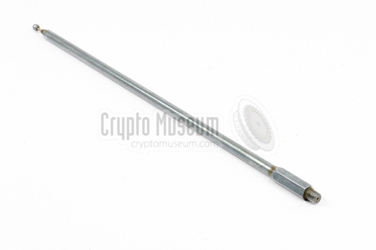
An external antenna can be connected to the BNC socket at the front.
Alternatively, a long telescopic antenna
with a threaded base can be used for short-range reception.
When the original telescopic antenna is used, the
antenna mounting block
should be fitted to the front panel first (see below).
|
|
|
When using the original telescopic antenna, the antenna mounting block
(usually stored inside the spares box) should be fitted to the mounting
holes at the top right of the front panel.
The mounting block is made of pertinax and can be fitted in two ways,
allowing the receiver to be used with the front panel in horizontal or
vertical position. It has a short coaxial cable by which it should be
fitted to the antenna input socket.
|
|
|
As the SRR-4 is suitable for a variety of power sources, three power
cables are supplied with the receiver, all of which can be connected
to the power socket at the right of the front panel.
Two mains power cables were supplied, one for 110C AC and one for 220V AC,
plus a 12V DC cable for connection to a car battery.
|
|
|
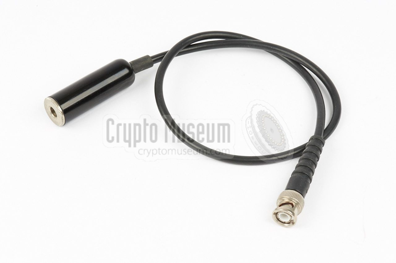
For unknown reasons, a BNC socket is provided at the receiver's front panel,
for connection of a pair of headphones. As most headphones are supplied with
a 6.3 mm jack however, this short adapter cable was supplied with the set.
As in practice this cable was often lost,
after-market adapters are commonly
found with the surviving receivers.
For connection of a recording device, a separate output with a fixed
audio level is also available at the front panel.
|
|
|
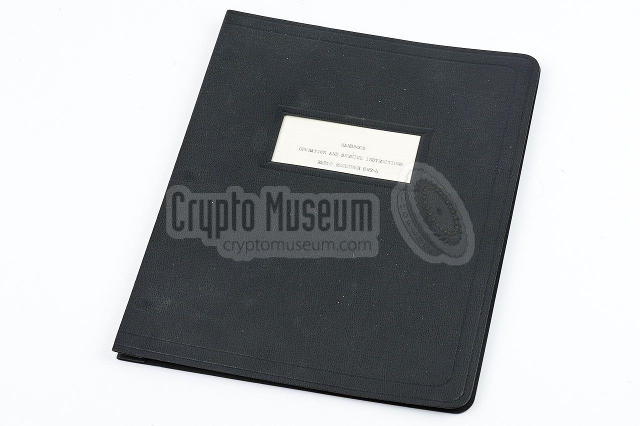
The SRR-4 was supplied with a 25-page A4-size handbook with full operating
instructions [A].
The manual was usually stored inside the leather carrying case,
in one of the side pockets.
Alternatively, a 52-page service manual
was available, with full operating instructions, circuit descriptions
and circuit diagrams [B]. Despite its age,
the circuit diagrams are of outstanding quality as they are professionally
printed, probably due to the fact that the SRR-4 was manufactured in
reasonable quantities.
➤ Download the operating instructions
➤ Download the technical manual
|
|
|
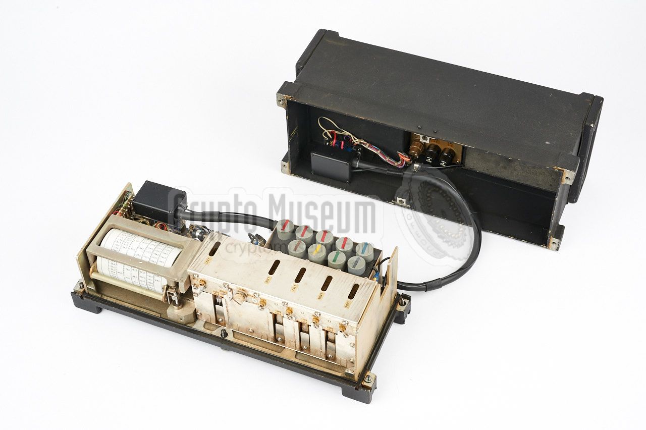
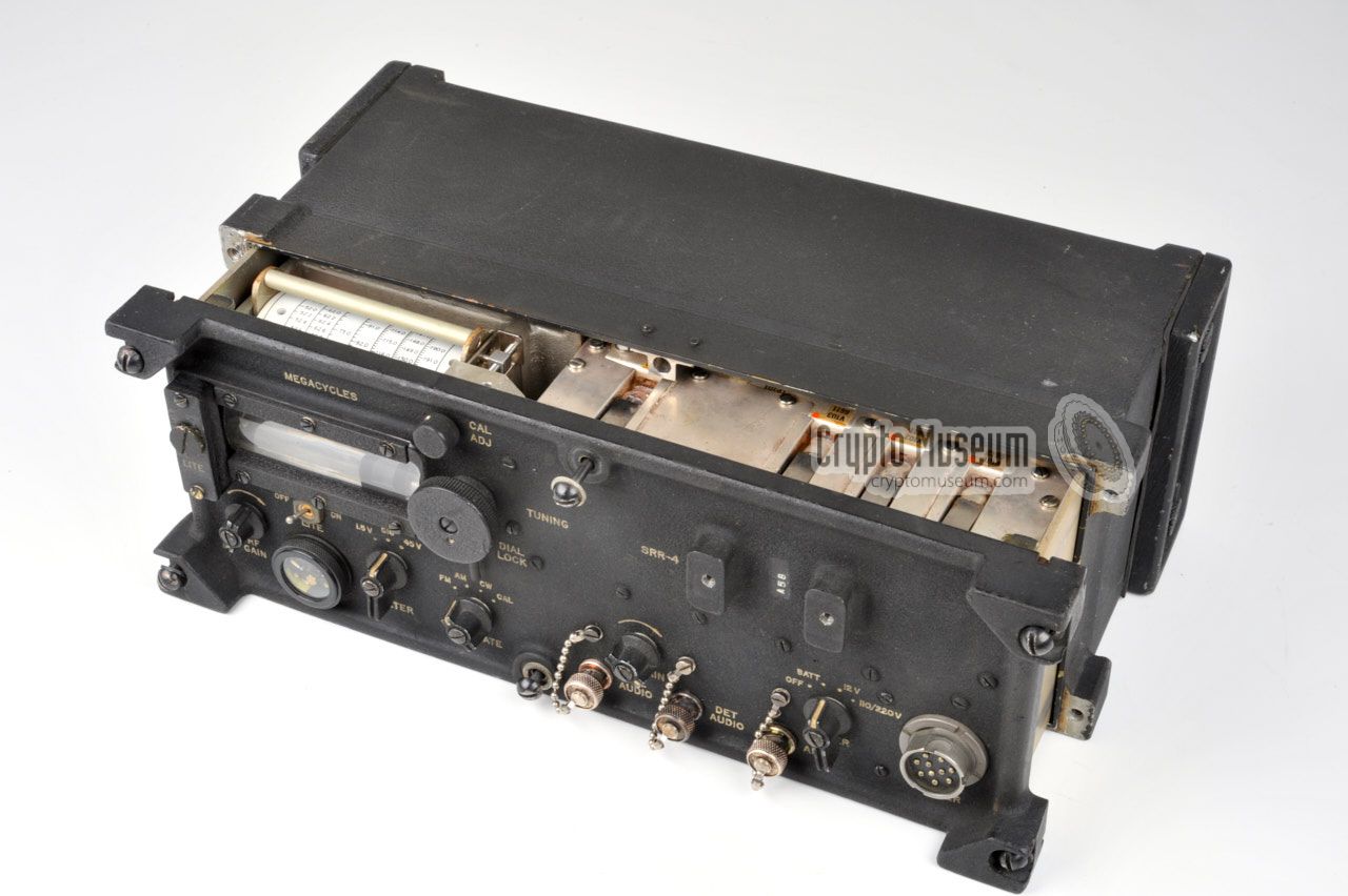
The diagram below shows the interior of the SRR-4, with its front panel
facing down and the helix-type frequency film scale drum on the left.
The location of the various parts and components is clearly visible, and
can be used as a guide when reading the description below.
|
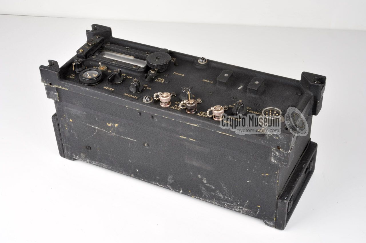
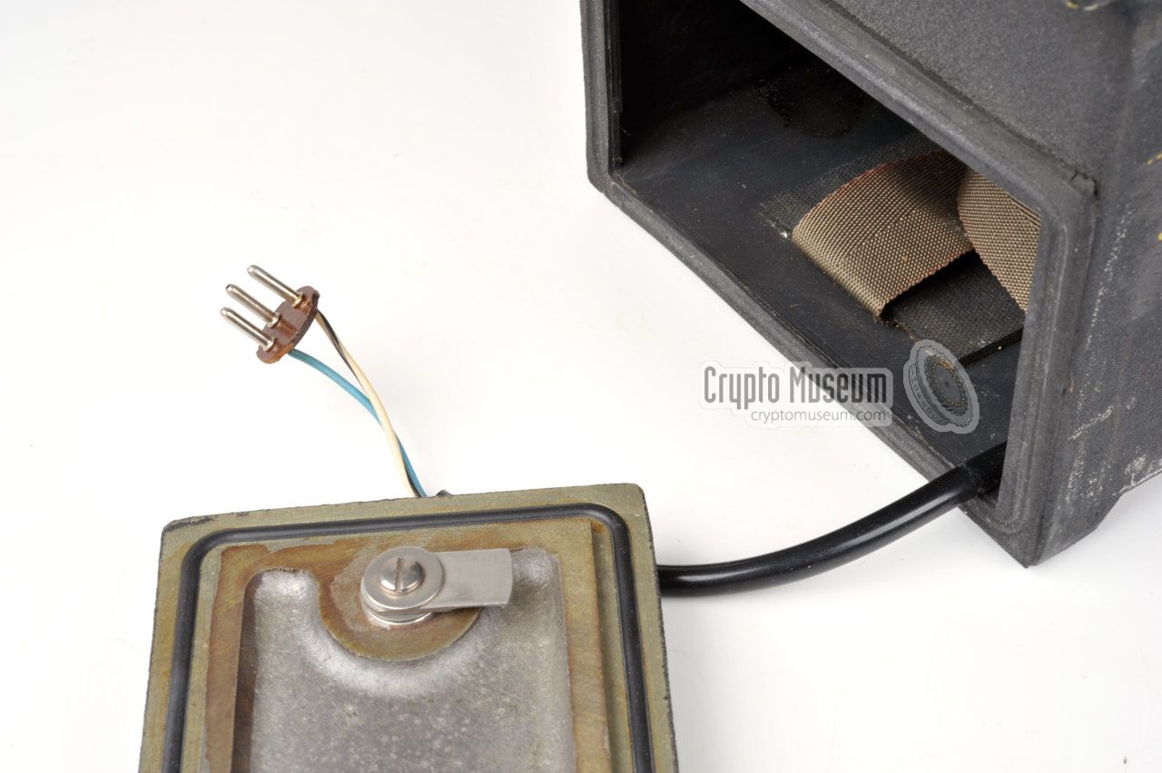
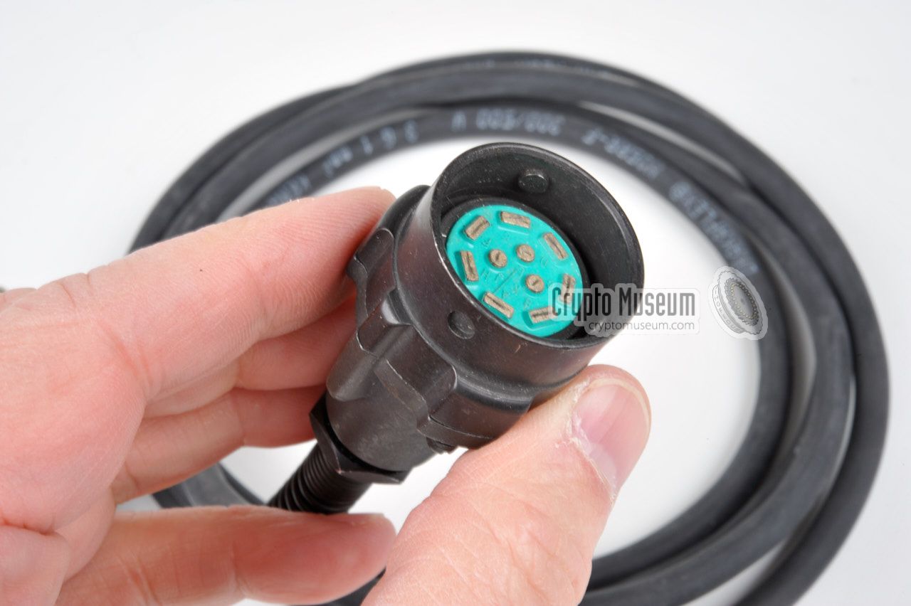
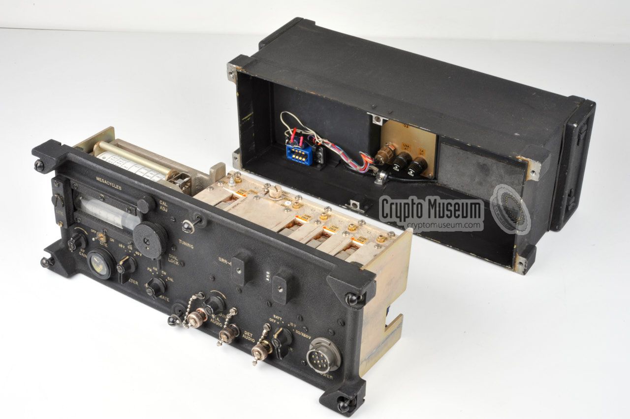
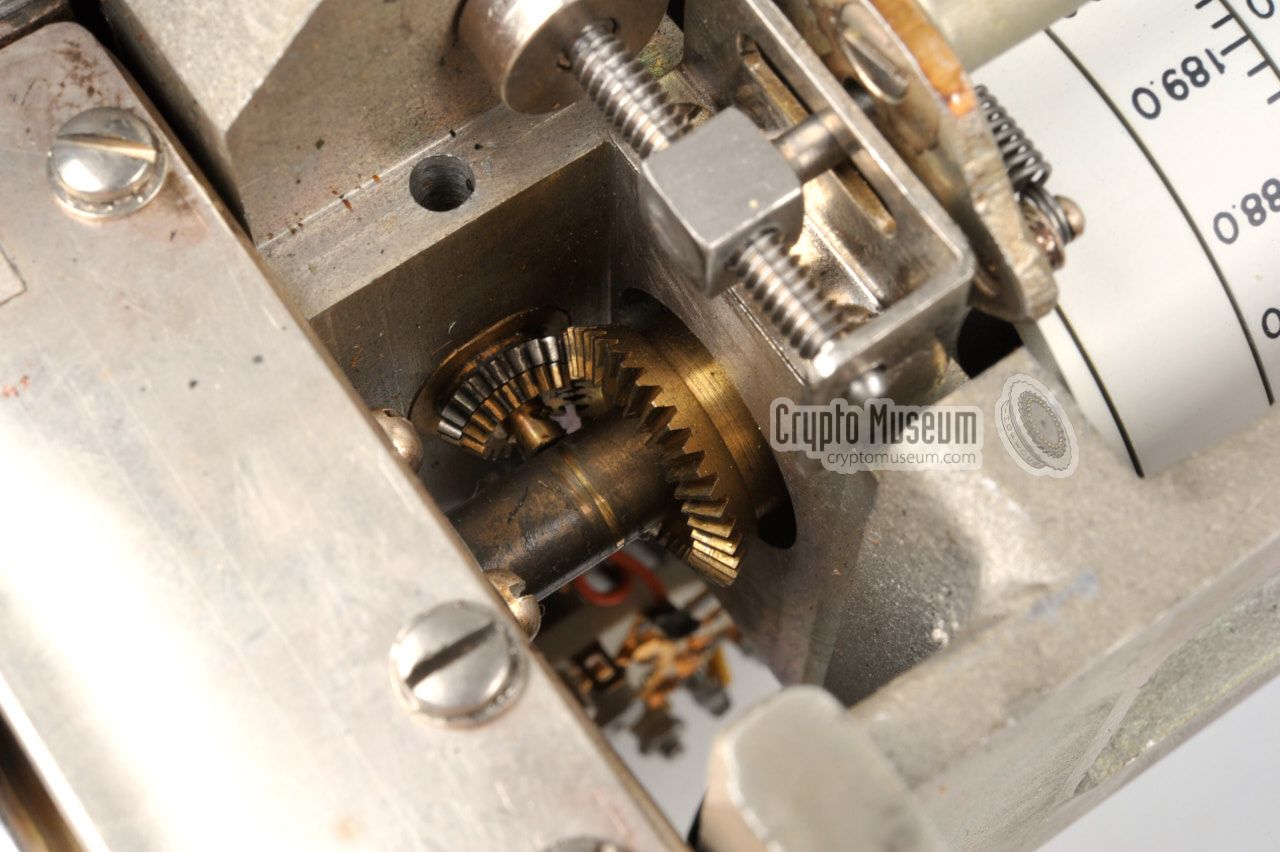
The image on the right shows the receiver after it has been removed from
the outer case shell, with the front panel facing downwards. At the right
is the film-type frequency scale which is driven by a
small gear box. At the
bottom right is a blue 8-pin plug
that connects the radio to the outer case
shell which holds the AC/DC PSU.
Along the bottom edge of the front panel are the connections and controls
of which the wiring
is clearly visible in the image on the right.
First-grade gold-plated plugs and sockets
are used to interconnect the various parts of the receiver.
|
|
|
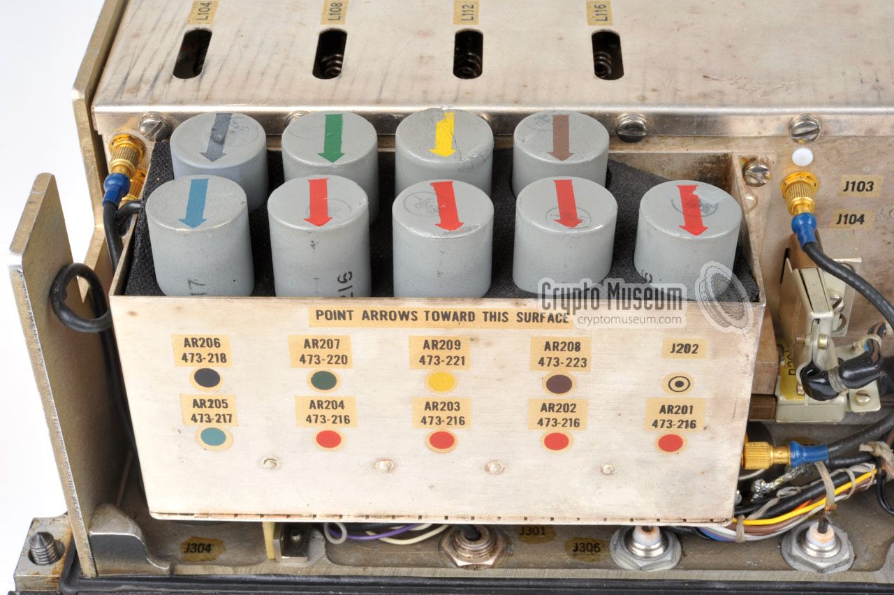
In order to save space and weight, the receiver is completely built with
subminiature valves,
four of which are visible at one
side of the front-end,
as shown in the image on the right. From left to right we see the 1st, 2nd
and 3rd RF amplifier and at the far right the local oscillator (LO).
These four valves are the only ones that are directly accessible. They are
socketed, so that they are easily replaced when necessary.
All other valves are mounted inside the cylindrical grey modules and can not
be accessed. In case of a defect, the entire module must be replaced.
|
|
|
In order to make servicing of the receiver even easier,
a set of spare modules
was supplied in the spares kit, along with several other spare parts.
Although this is very convenient from a service point of view at the time
the receiver was introduced, it makes it very difficult to repair a
vintage SRR-4 today, especially when the spares kit is missing and no
replacement modules are available.
The case shell contains the PSU, which is described in more detail in
the chapter Restoration.
|
Below is the simplified block diagram of the SRR-4. At the top left is
the antenna input. After filtering, the antenna signal is amplified in
a three-stage RF amplifier before mixing it with the signal from the
Local Oscillator (LO). The IF signal is then amplified by five identical
stages before it is fed to the AM detector and the FM discriminator.
It is then amplified to headphones level.
At the bottom left is the Power Supply Unit (PSU). It converts the AC mains
voltage to 12V DC and then converts the 12V DC into 1.5V DC (LT) and 40.5V
DC (HT). The unit can also be powered directly by -12V DC. In addition, it can
be driven by LT and HT batteries. In the centre position of the meter
selector switch, the meter shows the current through the last three IF stages.
|
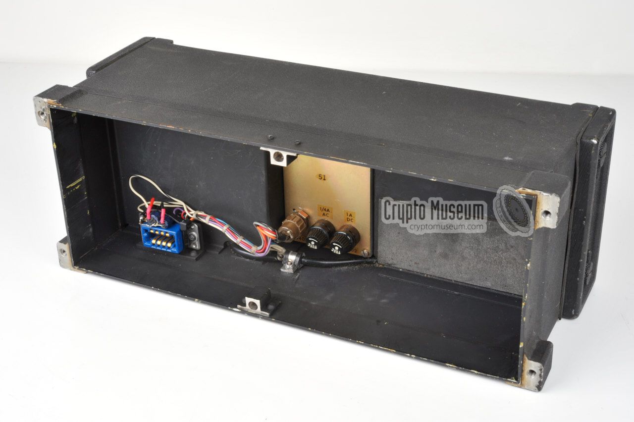
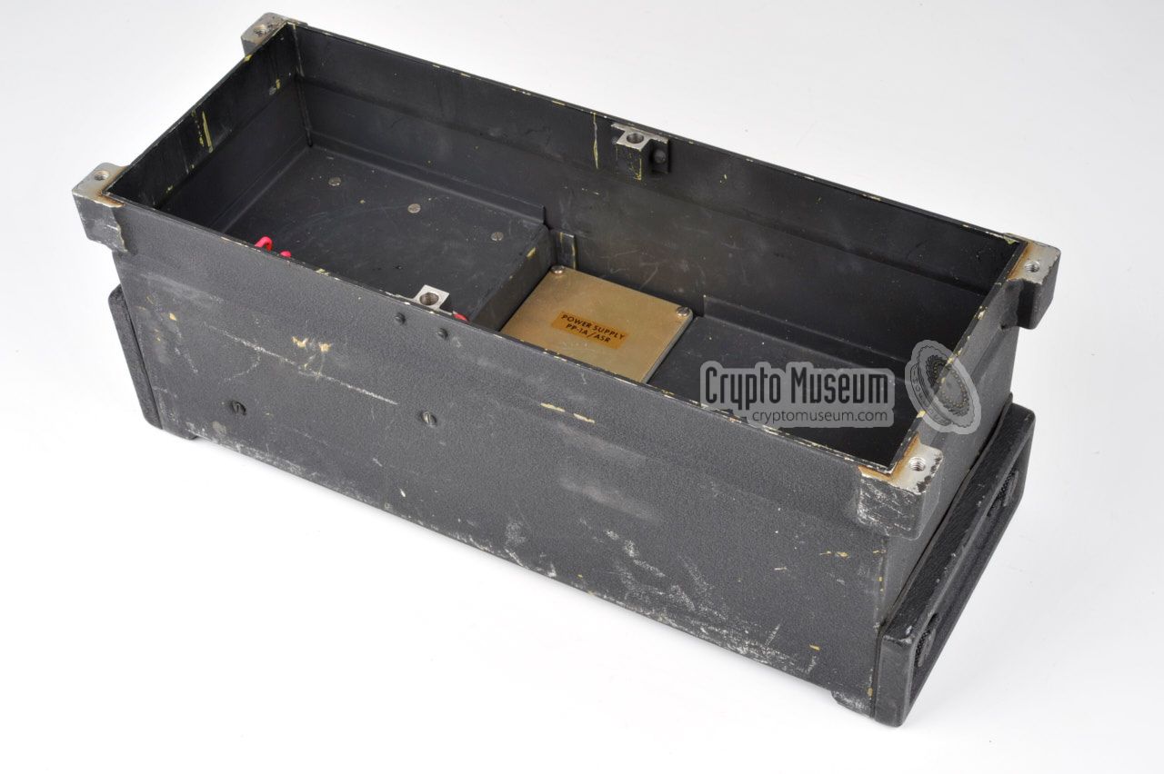
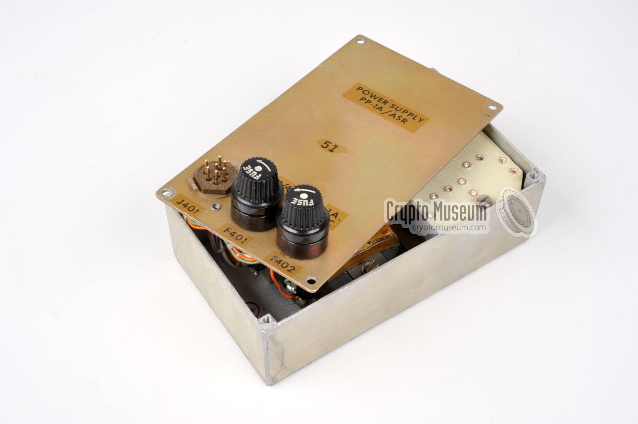
Getting access to the PSU is rather easy. Remove the outer case shell by loosening the six large bolts
at the edges of the front panel. Inside the case
are the two battery compartments (LT/HT) and a small metal box with the
PSU at the centre.
The PSU is held in place by 4 recessed screws at the bottom of the case shell.
After removing these 4 screws and removing the the 7-pin plug from socket J401
on top of the PSU, the entire PSU can be lifted from the case shell.
Note this plug may be locked. Now take off
the top lid of the PSU by removing the 4 screws at the top.
|
|
|
Inside the die-cast aluminium enclosure of the PSU are two compartments. The
one closest to the external connections is the mains transformer that converts
110V or 220V AC into -12V DC. The other compartment contains a separate
toroidal
transformer that converts the -12V DC input voltage into +40.5V (HT) and
+1.5V (LT). On top is a small PCB to which the wires are soldered.
|
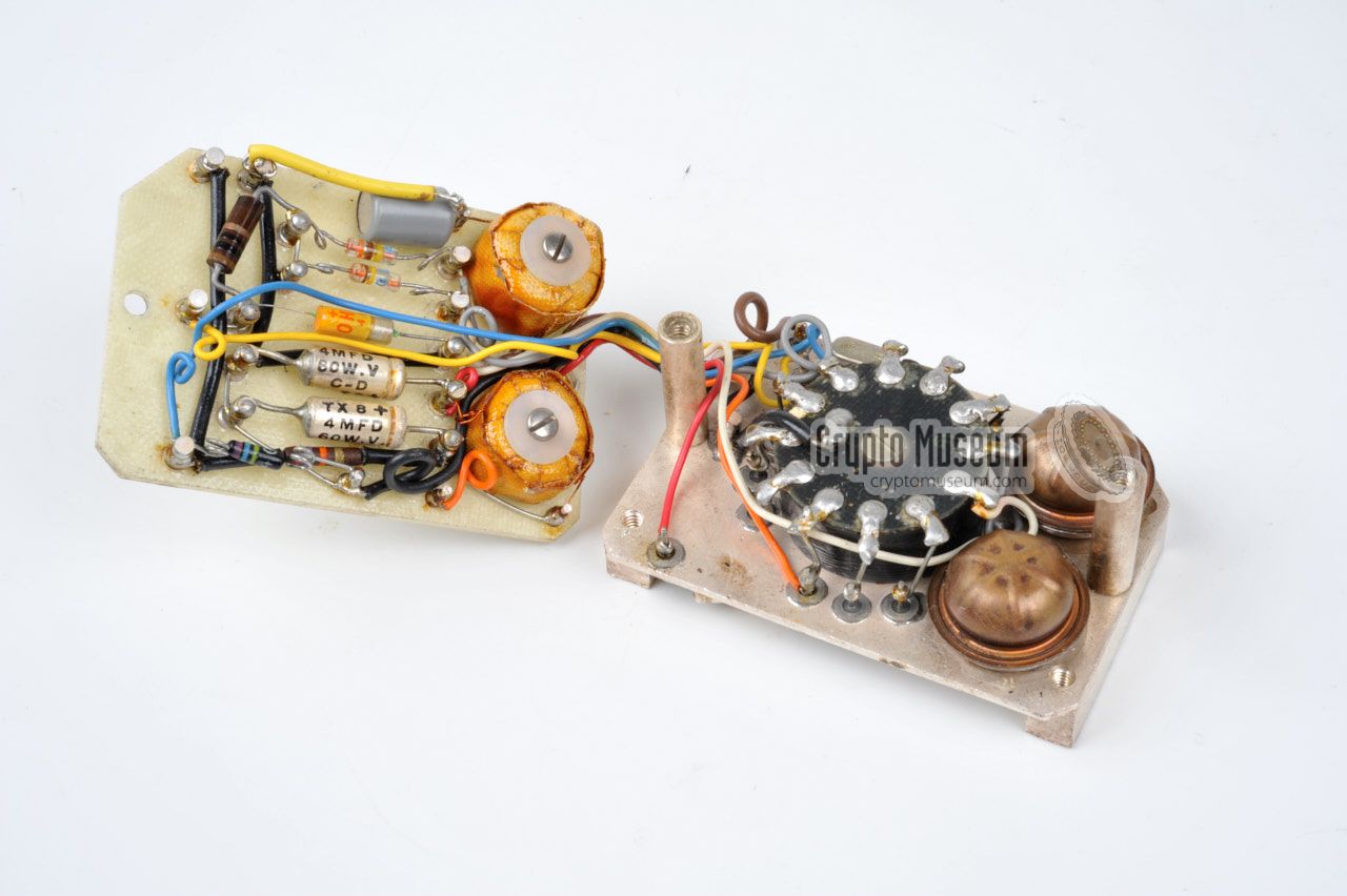
Make a note or a photograph of the wiring and then desolder the wires.
Now remove the secondary transformer by removing 4 recessed screws from the
bottom of the enclosure.
The secondary converter consists of two PCBs: one with the transformer and one
with additional components. The two can be separated by removing two screws from
the upper board.
In our case, it was immediately obvious that someone had previoously attempted
to repair the PSU, but had probably not been successful. Two capacitors had
already been replaced.
|
|
|
After wiring up the boards and measuring the ouput voltages everthing seemed
to be normal. However, as soon as a load was connected, the 1.5V LT rail
collapsed completely. This led us to the conclusion that the two diodes
in the LT power section (CR405 and CR406) were probably gone.
After replacing them, and swapping the earlier replaced cheap Japanese
capacitors for proper ones, everthing worked as expected,
and we were soon able to receive our first station.
|
- Tube 6051
- Tube 6611
- Tube 6612
- Diode 1N21B
- Pilot lamp
- IF amplifier subassembly 473-216 (red)
- IF amplifier/AM detector subassembly 473-217 (blue)
- FM discriminator subassembly 473-218 (black)
- Calibration oscillator subassembly 473-223 (brown)
- BFO subassembly 473-220 (green)
- AF amplifier subassembly 473-221 (yellow)
- Fuse 3AG 0.25A (2x)
- Fuse 3AG 1A (2x)
|
|
The following items are not supplied with the radio, but may be required
for full use:
|
- Batteries
- Headphones
- Recording equipment
- Line plugs
- Car antenna input adapter
|
|
Below is a timeline of the development history of the ASR-1, ASR-2 and SRR-4,
as compiled by Pete McCollum [1]. It is based on documents found in the
CIA archives.
|
|
Early 1956
|
|
TSS expresses the need for a surveillance receiver and asks the Army Signal
Corps about the service test results of their 20-100 MHz receiver (presumably
the R-744/PRR).
|
|
Jun 1956
|
|
First contact with the manufacturer Radio Receptor Co. in
New York (USA).
There are some design changes, such as a more flexible PSU.
|
|
Aug 1956
|
|
Radio Receptor Co. is asked to submit a budget for a separate
hi-band version that covers 50-175 MHz (in addition to the planned 20-100 MHz variant).
|
|
Nov 1956
|
|
Project officially expanded to include a lo-band and a hi-band version.
The requirements are specified to Radio Receptor Co.
12 hi-band units are initially requested.
|
|
Dec 1956
|
|
The projects are designated P-191A (lo-band) and P-191B (hi-band).
The range of the hi-band version is now specified at 50-250 MHz.
|
|
Feb 1957
|
|
Contract for the lo-band version received by Radio Receptor Co.
The contract for the hi-band version was probably received later that month.
|
|
Aug 1957
|
|
Model names defined as ASR-1 (lo-band) and ASR-2 (hi-band).
The first batch of ASR-1 receivers is expected in late October 1957.
|
|
Sep 1957
|
|
12 ASR-1 units (lo-band) are in production at
Radio Receptor Co.
The frequency range of the hi-band version (ASR-2) is now confirmed
to be 50-200 MHz (not 250 MHz as specified in December 1956).
Future ASR-1 units will be put out for bid to other contractors as well.
The final version of the AC Power Supply Unit (PSU) is demonstrated.
A possible ASR-3 version of the receiver is discussed, but this name
never turns up again in documents. It is possible that the ASR-3
eventually became the SRR-5.
|
|
Aug 1958
|
|
ASR-1 is being used for the evaluation of an
RT-3 covert listening device.
|
|
Late 1958
|
|
The ASR-2 (hi-band) becomes available in the field.
|
|
May 1960
|
|
The ASR-1 (lo-band) is used for the evaluation of an
RT-3R covert listening device.
This is the successor of the RT-3 of August 1958.
|
|
Feb 1961
|
|
ASR-2 renamed SRR-4. The exact date of the change is unknown.
From this point onwards, the units are marked SRR-4 on the front panel.
|
|
Mar 1965
|
|
Surveillance operation in Copenhagen (Denmark) in which
an SRR-4 is used for the reception of an SRT-5
covert listening device (bug).
➤ More
|
|
It is sometimes assumed that the SRR-4 was also used by the US Navy in
combination with the KY-71/UPX video decoder. However, the name (SRR-4)
should not be confused with that of the Naval AN/SRR-4 Radio Receiving Set.
The latter is a complete radar and IFF decoding setup,
used aboard US Navy ships from 1952 onwards, whilst 'SRR-4' is a
CIA designator.
The double use of model designators is quite common and often leads to
confusion. 1
|
The SRR-4 is based on the same design as the
R-744 surveillance receiver
that was developed by the US Army Signal Corps in 1957/58
for surveillance, intercepting enemy radio signals and RDF.
It was used by the US Army in Vietnam and was also
used in Canada and Australia.
The R-744 is housed in a similar enclosure and has a nearly identical
layout of its front panel, but there are some
notable differences, which are listed in the table below [1].
➤ More about the R-744
|
|
|
|
|
Differences between the SRR-4 and the R-744
|
|
|
| | SRR-4 | R-744 |
|
|
| Colour | Black | Green |
| Developed | ~1958 | ~1957 |
| Frequency range | 50-200 MHz (or 20-100 MHz) | 20-100 MHz |
| Audio socket(s) | BNC | Jack 6.3 mm |
| Power supply | 110/220V AC, 12V DC, batteries | 24V DC, batteries |
| Power socket | U79/U | 4-pin 24V vehicle socket |
| Scale illumination | ON/OFF | Adjustable |
| IF stages | 5 | 4 |
| Local oscillator | 1 tube 6051 | 2 tubes 6012 (parallel) |
| Mixer | 1N21B (diode) | 6611 (tube) |
|
|
|
Inter-unit power socket
J303
|
|
|
|
To allow the radio to be separated from the case shell (and hence the PSU)
without having to disconnect any wires,
an inter-unit connection is present, consisting of an Amphenol 26-182 plug
(P303) and an Amphenol 26-183 socket (J303).
To allow the receiver to be operated outside the case, a
service cable is provided in the spares kit.
Below is the wiring of the male connector (26-182), when looking
into the contacts. Note the presence of the extra wire (9), which is
not part of the bare connector. It connects the receiver's chassis
to the GND connection of the PSU.
|
- +1.5V DC (from battery)
- +1.5V DC (from PSU)
- +40V DC (from PSU)
- +45V DC (from battery)
- -12V DC (to PSU)
- AC common (to PSU)
- 110V AC (to PSU)
- 220V AC (to PSU)
- GND (chassis)
|
|
|
|
Internal power socket
J401
|
|
|
|
The internal PP-1A/ASR
power supply unit is fully separated from the rest of the radio,
and is housed in a small metal enclosure that is mounted at the bottom of the
outer case shell. The PSU
converts 110/220V AC to 12V DC and then converts the
12V DC to 40.5V DC (HT) and 1.25V DC (LT) for the filaments. This 2-stage
power conversion was necessary to allow the radio to be powered by an external
12V DC source as well. The socket on the PSU is wired as follows:
|
- 0V DC (GND) (in)
- -12V DC (in)
- +1.25V (out)
- +40.5V (out)
- 110V AC (in)
- 220V AC (in)
- 0V AC (AC common) (in)
|
|
|
This connector is a 7-way 126-series hexagonal connector, made by
Winchester Electronics, Amphenol, Continental, and probably others.
|
|
|
External power socket U-79/U
J304
|
|
|
|
An external power source can be connected to the U-79/U socket marked
EXT POWER (J304) at the bottom right of the front panel.
It accepts a U-77/U plug and allows
the receiver to be powered by 12V DC, 110V AC or 220V AC. Note that in the
case of 12V DC, the unit has the (+) terminal connected to ground.
The pinout of the front panel connector is as follows:
|
- 0V AC (AC common)
- 0V DC (GND)
- 0V DC (GND)
- -12V DC (in)
- not connected
- 110V AC (in)
- 220V AC (in)
- not connected
- not connected
- not connected
|
|
When powering the SRR-4 from the 220V AC mains, e.g. in Europe,
the power cable should be wired as follows. The pinout of the U-79/U
socket is as seen when looking into the contacts of the socket. This
is identical to the solder side of the plug.
|
WARNING —
Always connect the U-79 plug to the radio before connecting the other
end to the wall socket. When removing the cable, always disconnect
the wall socket first.
The contact pins of the plug
carry a potentially lethal voltage. Don't touch the contacts whilst
the cable is connected to the mains.
When powering the SRR-4 from the 110V AC mains, e.g. in the USA,
the power cable should be wired as follows. The pinout of the U-79/U
socket is as seen when looking into the contacts of the socket. This
is identical to the solder side of the plug.
|
WARNING —
Always connect the U-79 plug to the radio before connecting the other
end to the wall socket. When removing the cable, always disconnect
the wall socket first.
The contact pins of the plug
carry a potentially lethal voltage. Don't touch the contacts whilst
the cable is connected to the mains.
When powering the SRR-4 from a 12V DC power source, such as the battery
of a car, the power cable should be wired as follows. The pinout of the U-79/U
socket is as seen when looking into the contacts of the socket. This
is identical to the solder side of the plug. Note that the positive terminal
(+) of the battery should be connected to the chassis (ground) of the
receiver.
|
Device Surveillance receiver Purpose Spectrum monitoring, bug reception Principle Superheterodyne Model SRR-4 Developer CIA, TSS Manufacturer Radio Receptor Co. Inc. (NewYork, USA) Year 1956-1958 Frequency 50-200 MHz (single band) Waveform AM, FM, CW, MCW Sensitivity FM/CW: <1µV
AM: <1.5µV (50-100 MHz), <2µV (100-200 MHz) IF 4.3 MHz Bandpass 80 kHz Calibration 5 MHz intervals (2 MHz on the ASR-1) Mains 80-130V AC or 160-240V AC (40-80 Hz) Battery 11-20 V DC (neg), 270 mA max. Dimensions ? Weight ?
|
5 Jeremy T. (USA) 16 Pete McCollum 42 William Brinsmead (USA) (via radiomuseum.org) ??? International Spy Museum, Washington DC (USA)
|
A58 Private collector, Netherlands A59 Pete McCollum A79 Crypto Museum ??? Military Collection Gausdal ??? International Spy Museum, Washington DC (USA) ??? International Spy Museum, Washington DC (USA)
|
|
The following abbreviations and cryptonyms are used throughout this page
and the referenced documents:
|
|
AM
|
|
Amplitude Modulation
|
|
AQUATIC
|
|
TSS
CIA cryptonym for the Technical Services Staff (TSS)
(later: TSD)
of the CIA.
|
|
FM
|
|
Frequency Modulation
|
|
CA
|
|
West Germany
CIA cryptonym for West Germany (BRD).
|
|
CATIDE
|
|
BND
CIA cryptonym for the German Bundes Nachrichtendienst BND.
Note that the first two letters (CA) indicate West Germany.
|
|
CIA
|
|
Central Intelligence Agency
Independent US Government civil agency for gathering national
security intelligence from around the world.
(More)
|
|
CW
|
|
Continuous Wave
|
|
DIZTAG
|
|
Chzechoslovakia
CIA cryptonym for the former Replublic of Czechoslovakia.
|
|
KURIOT
|
|
TSS
CIA cryptonym for the Technical Services Staff (TSS)
(later: TSD)
of the CIA.
|
|
MCW
|
|
Modulated Continuous Wave
|
|
MK
|
|
TSD operation
CIA cryptonym for an operation of the CIA's Technical Services Division (TSD).
|
|
MKTOPAZ
|
|
TSD
Technical Services Division (TSD) of the CIA.
Operations include preparation of false documents and identity materials.
|
|
TSD
|
|
Technical Services Division
The Technical Services Division of the CIA. In 1974 renamed
Office of Technical Service (OTS).
|
|
TSS
|
|
Technical Services Staff
In February 1960 renamed TSD.
|
|
UJRANDOM
|
|
BND investigation
CIA cryptonym used as Cable Indicator for BND investigations.
|
-
Basic handbook kindly supplied by Pete McCollum [1].
|
|
-
Declassified by the CIA in 2006.
-
Sanitized copy approved for release by CIA in 2011.
|
|
|
|
Any links shown in red are currently unavailable.
If you like the information on this website, why not make a donation?
© Crypto Museum. Created: Thursday 14 April 2016. Last changed: Saturday, 25 April 2026 - 06:51 CET.
|
|

|
|
|
|