|
|
|
|
|

|
|
Receivers TSCM CIA
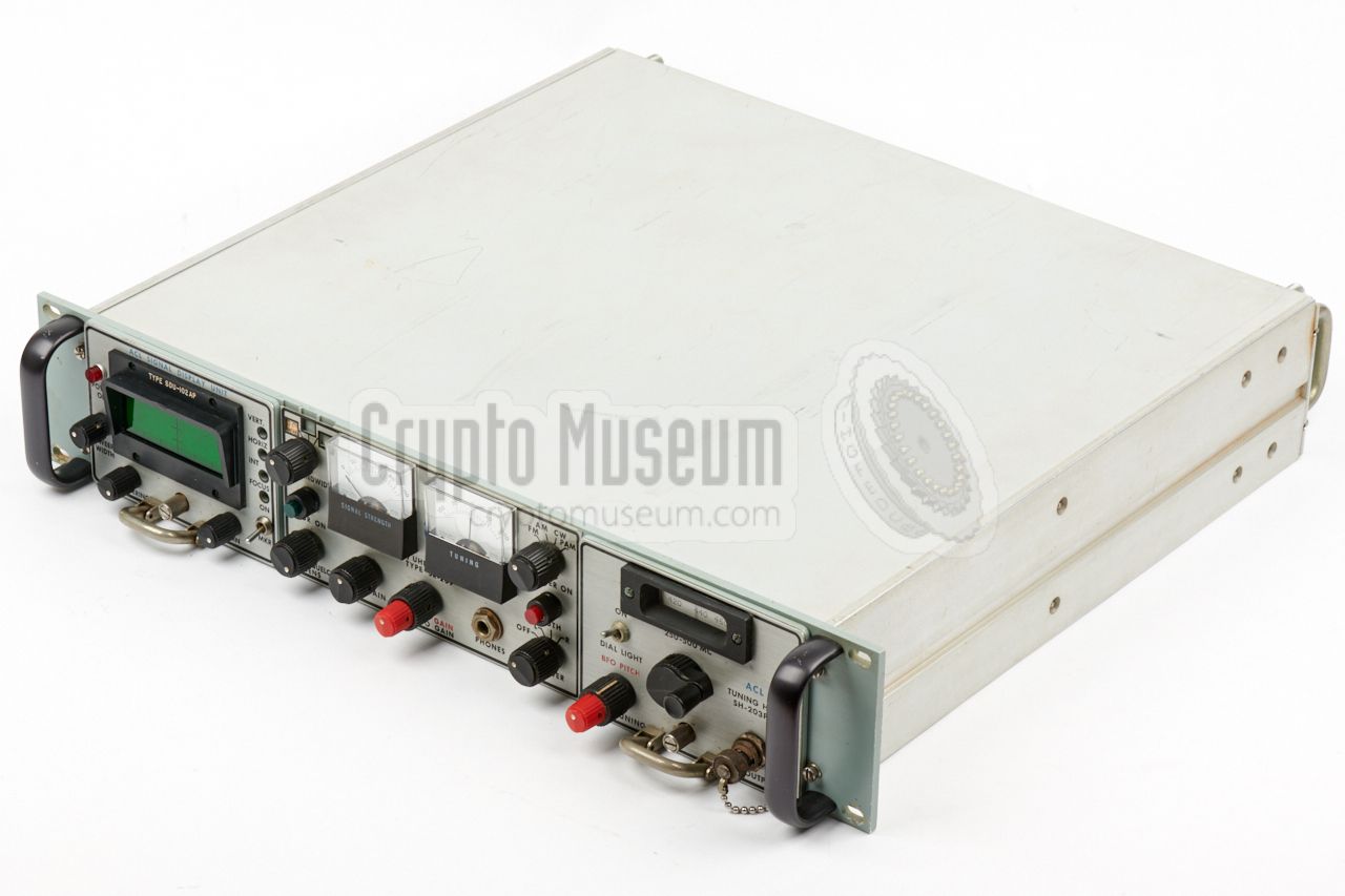
The receiver is housed in a 19" 2U rackmount enclosure and offers
space for two same-size plug-units; one at either side of the fixed IF/AF
unit at the centre. Depending on the application, it can accomodate
two tuning heads, or a
signal display unit (SDU)
plus a single tuning head
[B].
The image on the right shows a typical SR-209 that is equipped for reception
of the
CIA bugs
of the 1960s and 70s, which operated in the 380 MHz frequency
band. At the left is a green SDU-102AP
CRT
display unit.
At the right is the SH-203P-1 tuning head
that covers 250—500 MHz.
|
|
|
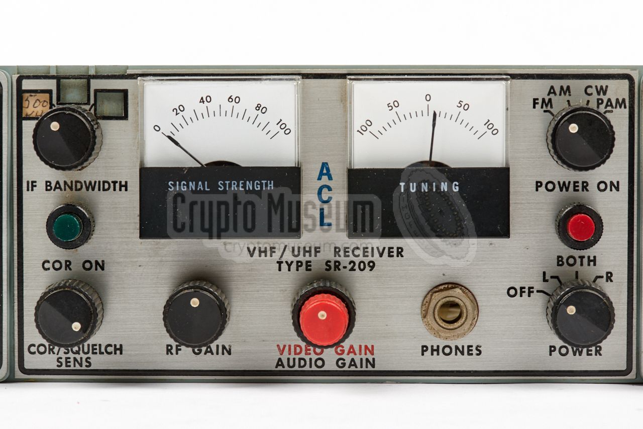
The receiver is suitable for the reception of AM,
FM
and CW signals,
and also for pulse-modulated signals, which were generated by some of the
CIA's covert listening devices (bugs)
of the era. The IF2 is at 21.4 MHz 2 which is also used to display the
IF passband on the signal display unit (SDU).
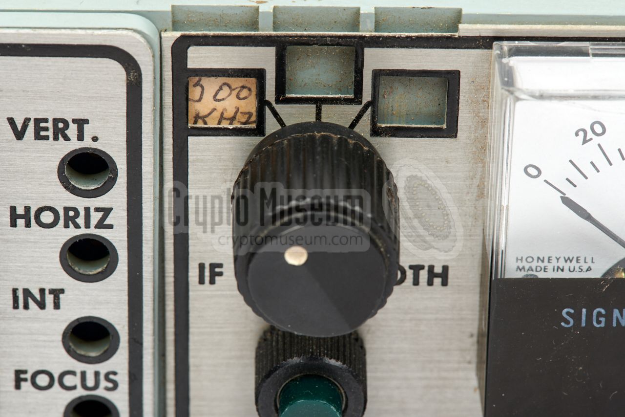
Up to three different IF strips can be installed – plus a spare –
to allow for different bandwidths. With the receiver shown here,
300 kHz, 500 kHz, 2000 kHz and 3000 kHz IF strips are present.
In the Swiss Army, the SR-209 was known as E-648
[3].
Within the CIA
it was known as SRR-23
[6].
|
-
The SR-209 was initially advertised as a 2-7000 MHz receiver [B],
but a plug-in for the 7-12 GHz band was later added to
range of available tuning heads,
making it effectively a 2-12000 MHz receiver [C].
-
When using the SH-100-series tuning heads, the IF2 is at 455 kHz.
|
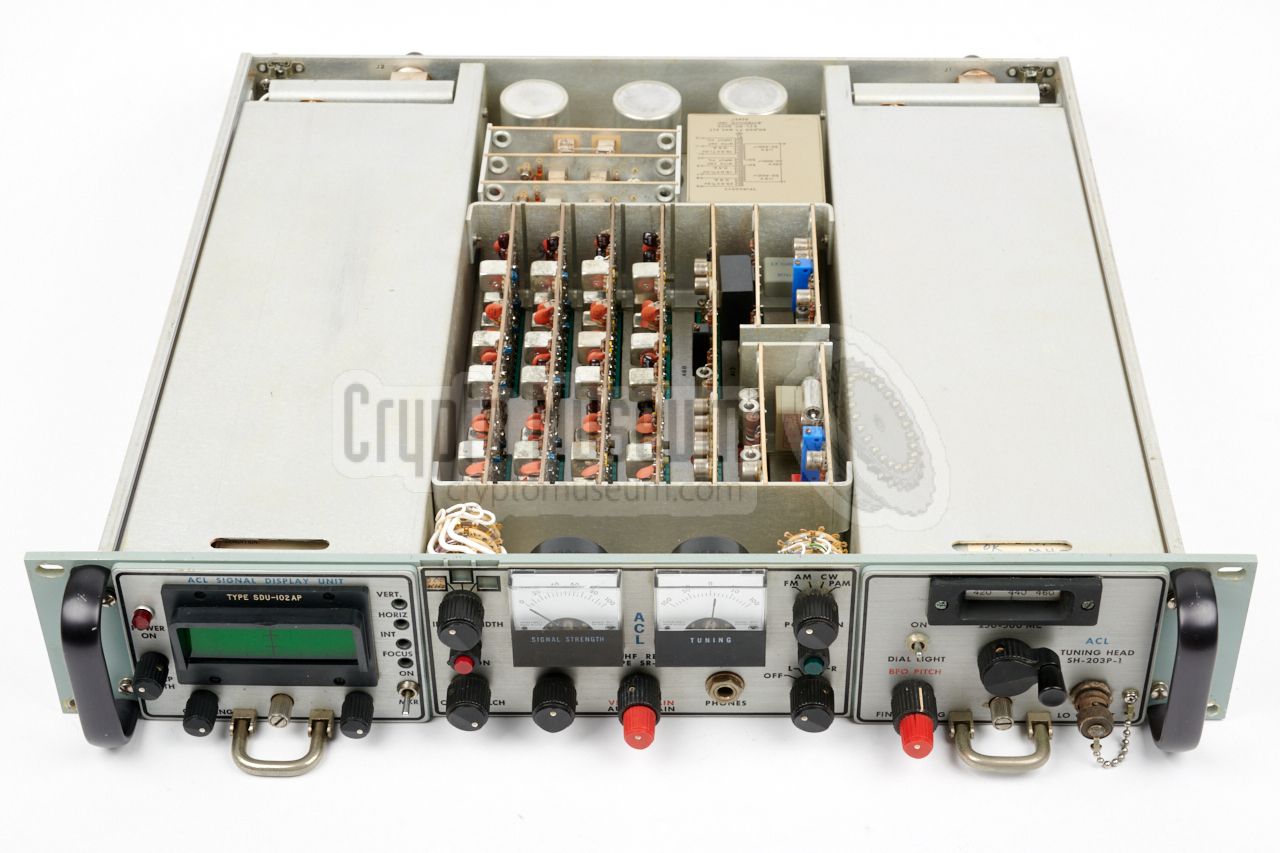
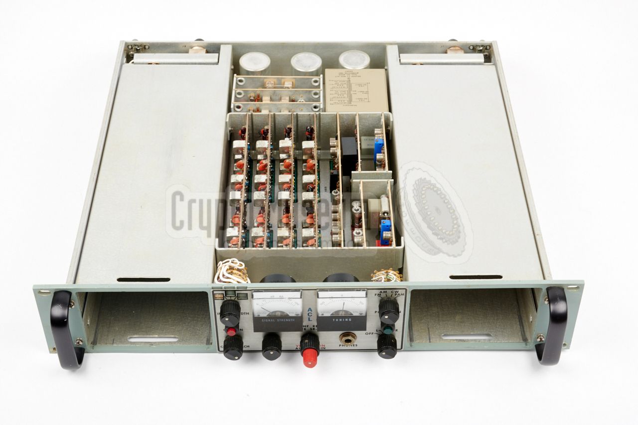
The SR-209 has a modular construction. It is housed in a 2U 19" rackmount
case that consists of three major parts: a mainframe – which contains the
power supply unit (PSU), the Intermediate Frequency sections (IF) and the
audio circuits (AF) – at the centre, and two expansion bays at the left and
right sides respecively. Each of the bays can hold a tuning head
– or RF front-end –
but the one at the left is also suitable for a
Signal Display Unit (SDU) – or frequency spectrum display.
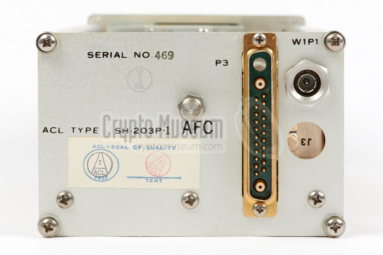
The diagram above gives an overview of the front panel, which has an
SDU-102AP Signal Display Unit
at the left, and an
SH-203P-1 tuning head at the right.
In this configuration, the receiver – which has previously been owned by the
CIA – is suitable for the 250 — 500 MHz band, which covers the
380 MHz band
in which many of the
CIA's
covert listening devices (bugs)
operated.
All connections – with the exception of the headphones socket – are located at
the rear, as shown in the diagram above. As each expansion bay can take a
tuner, there are two N-type sockets for connection of the antennas.
At the left is the 115/230V AC mains power input, which requires a rather
special type of plug.
The desired local voltage is selected with two toggle
switches at the right. Once configured, they are protected by a metal cross bar,
to prevent accidental change.
|
The enclosure can be seen as the main frame. It contains a mains power supply
unit (PSU), three power stabilizing circuits, up to three different
IF strips (plus a spare one) and the AF circuits, like AFC,
squelch and audio (headphones) amplifier.
It also holds the control panel at the centre. This section is identical for all
variants of the SR-209, although the IF strips can be selected at will. The
base unit has two expansion bays, each of which can accomodate two
different tuners, or a single tuner and a
Signal Display Unit (SDU).
|
|
|
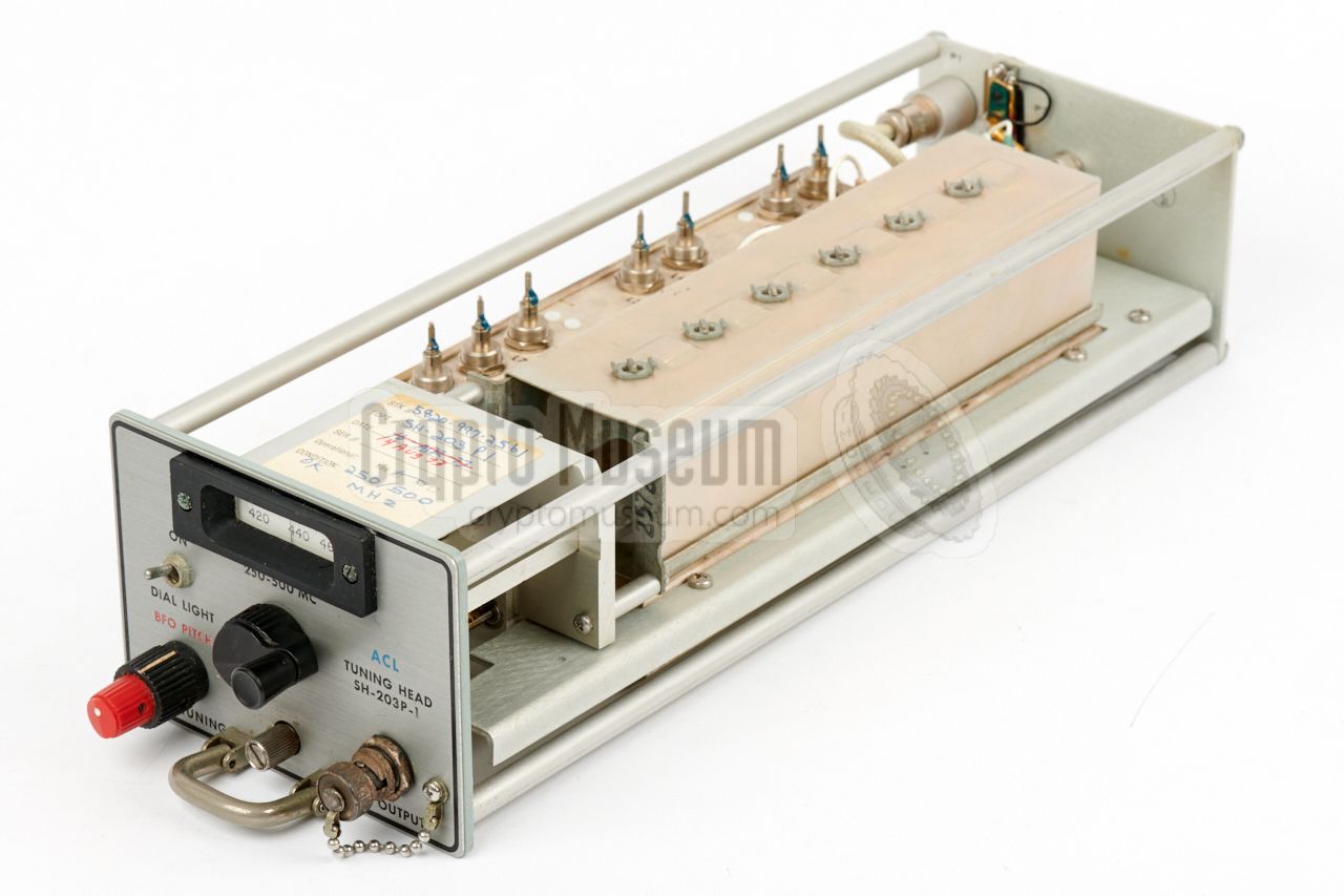
The receiver is suitable for frequencies between 2 MHz and 12 GHz,
divided over 14 bands, each requiring a dedicated tuning head, or
tuner. The main frame can accomodate two such tuners.
The image on the right shows the SH-203P-1 tuner, which covers the 250 —
500 MHz band, in which many CIA bugs
operated at the time.
➤ Overview of available tuning heads
|
|
|
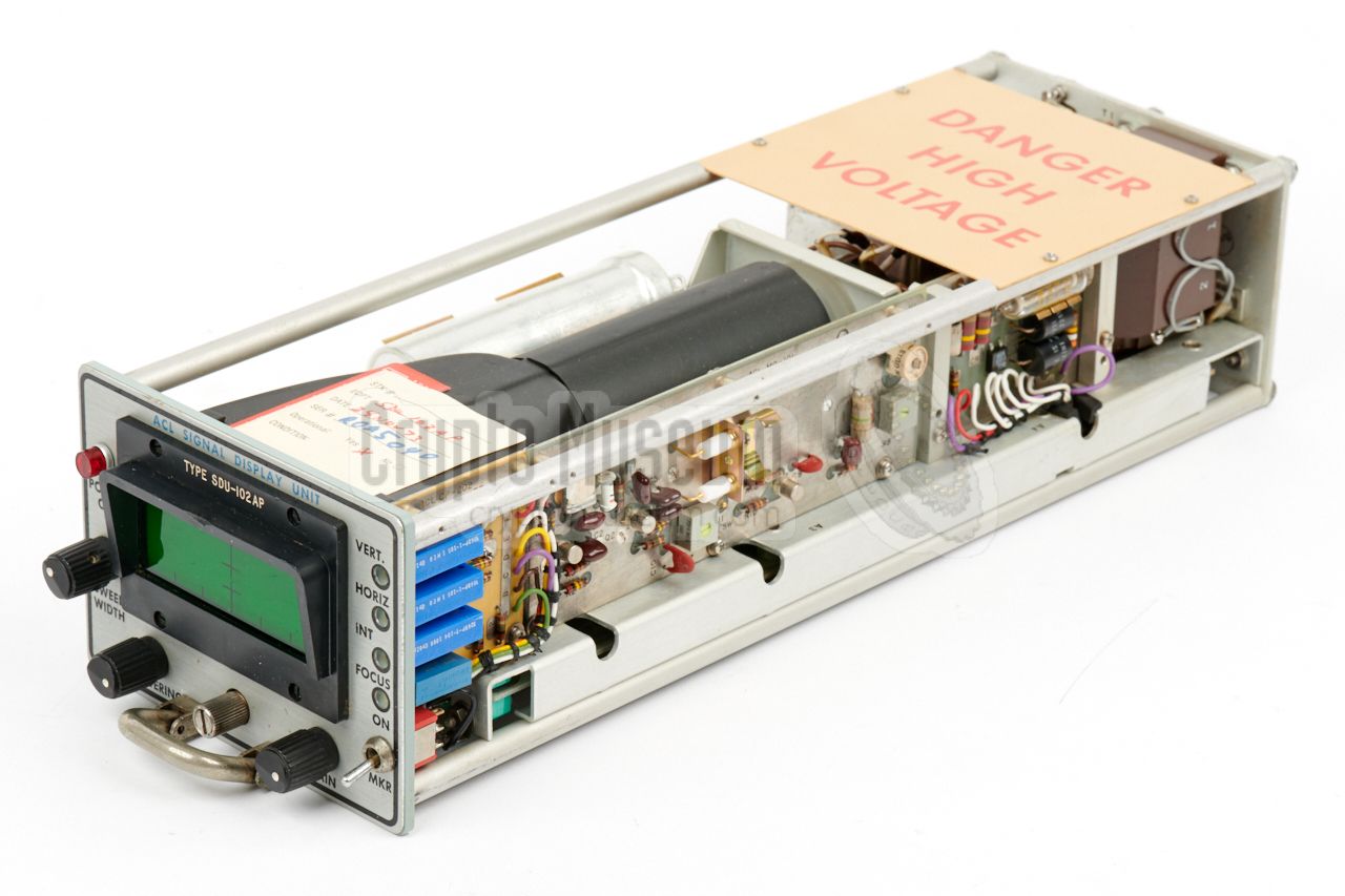
For surveillance and countermeasures jobs, it can be useful to have a real-time
visual display of a section of the radio spectrum. In such cases a Signal
Display Unit, or SDU, could be installed in the leftmost expansion bay. Two
such SDU's were available: one for the 2 — 45 MHz range, and one for the
45 — 12000 MHz range.
The SDU is built around a classic green phosphor cathode ray tube (CRT),
and displays RF signals between DC and 3 MHz in the IF passband.
The image on the right shows the SDU-102AP.
|
|
|
|
|
Intermediate Frequency plug-in
IF
|
|
|
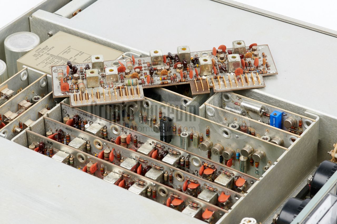
The receiver can be configured for up to three different IF bandwidths,
that are selected with a rotary switch at the front panel.
Each bandwidth requires
a dedicated IF-strip
to be installed in the IF-slots at the centre part of the mainframe.
Four IF-slots are present, of which only the leftmost three are wired to the
selector. The rightmost slot can hold a spare IF-strip. The image on the right
shows three installed IF-strips (300, 500 and 2000 kHz), with a spare one
(3000 kHz) extracted from its unwired slot, laying on top.
➤ Overview of available IF-strips
|
|
|
The SR-209 has a rather exotic AC mains power input socket at its
rear panel, which requires a
special type of plug.
It is suitable for 115V and 230V AC, but the two voltage selection
switches at the rear panel must be set to the correct voltage,
prior to connecting the mains cable.
The image on the right shows the original power plug with integrated bajonet
fitting. For safety reasons, the original rubber cable (which had
become brittle over the years) has been swapped for a new one, and the US-style power plug
has been swapped for a European continental one.
|
|
|
Audio is provided at the 6.3 mm jack socket at the front,
at a level that is suitable for a pair of 150Ω - 600Ω headphones.
When using high-impedance headphones,
a 150 ohm shunt resistor should be connected in parallel.
A separate 600Ω balanced output
is available at the rear
for connection to an external amplifier.
|
|
|
Original documentation of the SR-209 is very hard to find. Luckily,
our receiver came with most of the original manuals intact, which
are available for download below. So far, we have only recovered
the manuals of the base unit, one of the tuning heads and two of
the IF-strips.
We are still looking for the manual of the Signal Display Unit SDU-102AP.
Please help us to expand this page, by providing that manual.
➤ Get the manuals
|
|
|
The operation of the SR-209 is explained in the simplified block diagram below.
At the top is a typical tuning head (tuner) for UHF reception. It has a free
running Variable Frequency Oscillator (VFO) that operates 60 MHz above the
desired frequency (Fc), resulting in a 60 MHz IF1 signal.
The IF1 signal is mixed with 81.4 MHz from a Voltage Controlled Oscillator (VCO),
which results in a 21.4 MHz IF2 signal, that is fed to one of (up to three)
IF-strips in the receiver's mainframe.
Note that different IF-strips are available, for different frequency
ranges and for different bandwidths. The block diagram above shows typical
IF-211, IF-212 and IF-112 strips.
Each IF-strip produces AM and FM signals,
that are fed to the Automatic Gain Control (AGC), the (optional) Automatic
Frequency Control (AFC), the Carrier Operated Relay (COR, or squelch), the
video amplifier (VA) and the audio amplifier (AA). The signal strength
indicator is driven by a signal from the AGC, whilst the tuning indicator
shows the discriminator signal from the video amplifer.
|
|
The mainframe is housed in a strong 19" 2U rackmount enclosure. The interior
can be accessed by removing the top and bottom covers, each of which is held
in place by two knurled bolts at the rear. After loosening these bolts, the
cover panels can be slid towards the rear and removed.
|
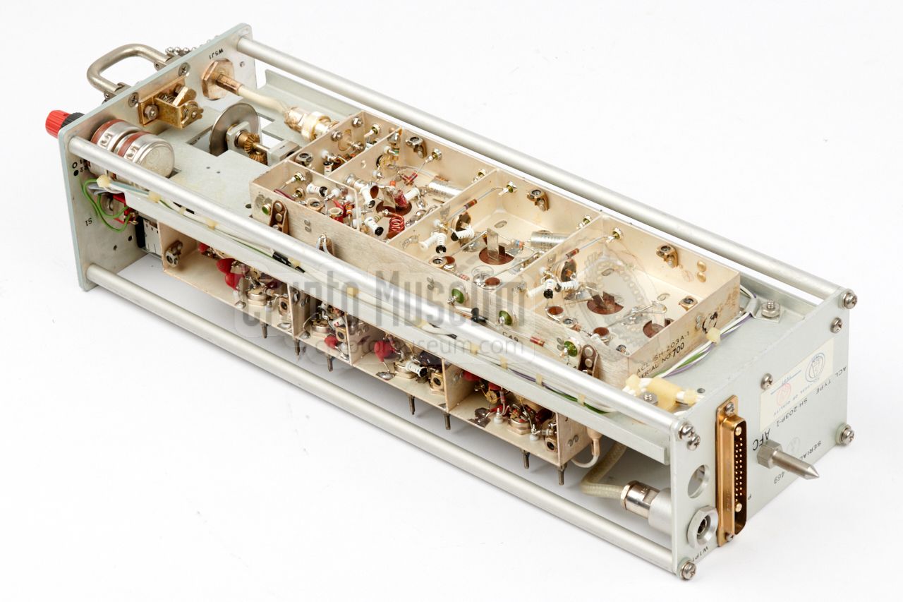
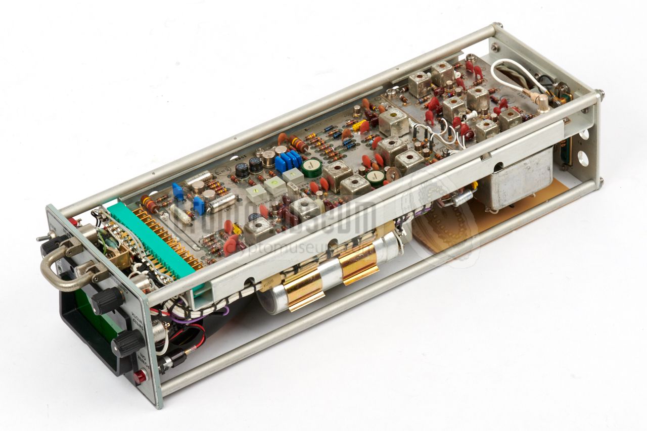
Inside the case is an aluminium construction that holds the parts that are
common to all SR-209 models. At the rear is a heavy mains transformer
with three stabilizing circuits on plug-in cards:
one for +24V,
one for +12V
and one for -12V.
Towards the front are five long plug-in cards, and four smaller ones.
From left to right are up to three IF-strips,
plus a 4th spare one, followed by the AGC board.
The smaller boards hold the (optional) AFC unit,
the COR (squelch),
the video amplifier (VA)
and the audio amplifier (AA).
The latter delivers the output to the headphones.
|
|
|
|
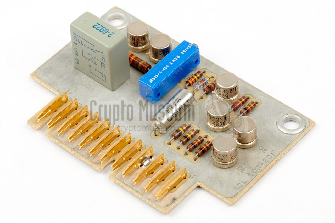
The audio signal is also available on a terminal block
at the rear. COR, the
carrier-operated relay, allows the audio to
be switched off when no carrier is detected. A set of free contacts from this
relay is also available on the terminal block at the rear.
The green lamp is lit when COR is active.
|
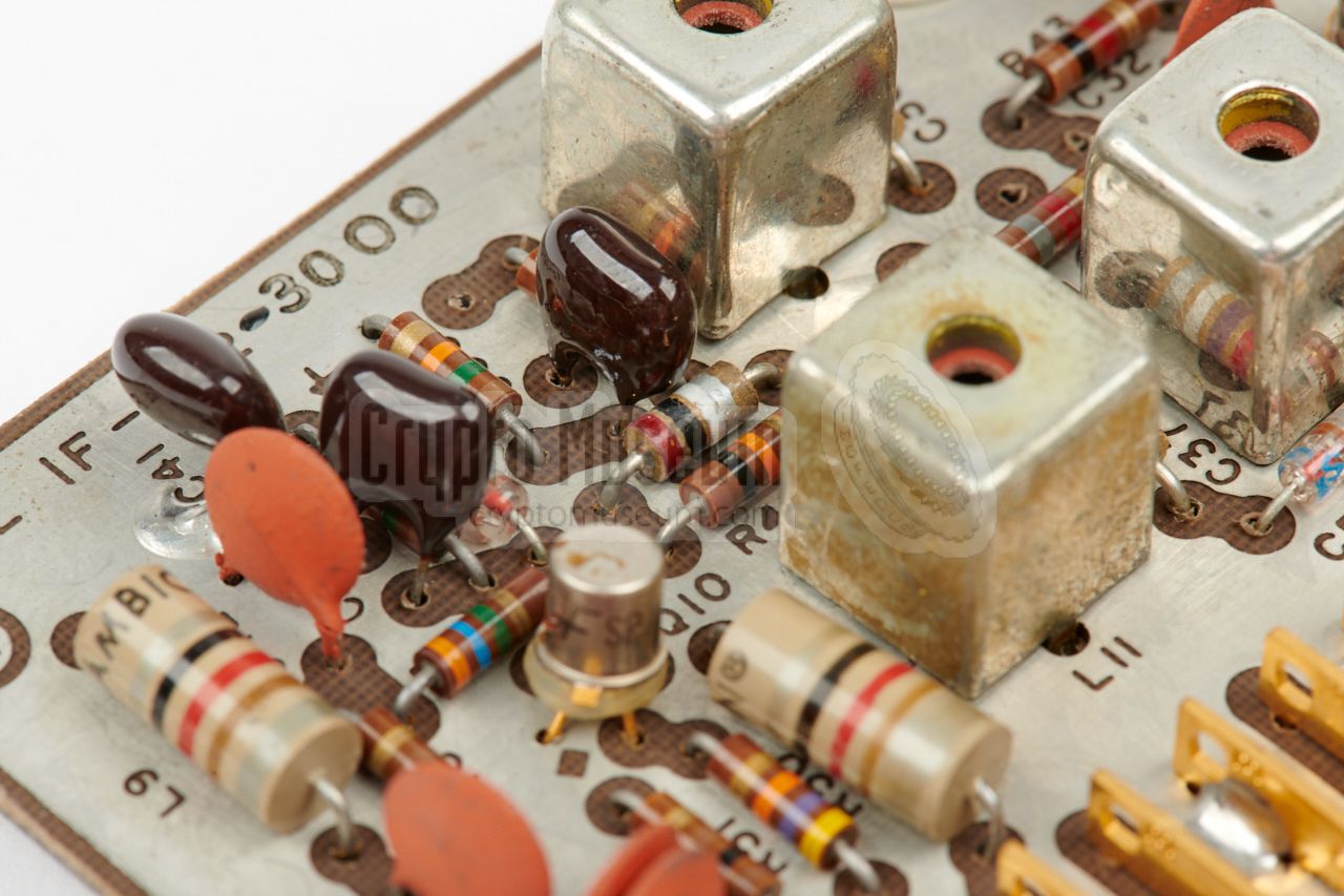
Depending on the selected frequency segment and the requirements of the user,
up to three IF-strips
can be fitted inside the mainframe. The image on the
right shows a typical IF-212-3000 IF-strip, that offers a bandwidth of 3000 kHz.
It is likely that this strip was used for the reception of pulse-modulated
listening devices (bugs).
An unwired slot in the base unit, allows a spare (4th) IF-strip to be stored
inside the receiver. It can be swapped with an active one,
in just a few minutes. For this reason, the text in the windows
above the rotary selector can also be swapped.
|
|
|
|
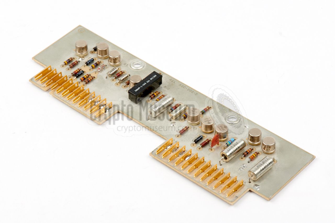
Each IF-strip directly produces an AM and an FM signal that are used for
several purposes. The AM detector produces the signal for the AGC,
whilst the FM discriminator drives the AFC. Both circuits remain active,
even when the alternative modulation type is selected by the operator.
|
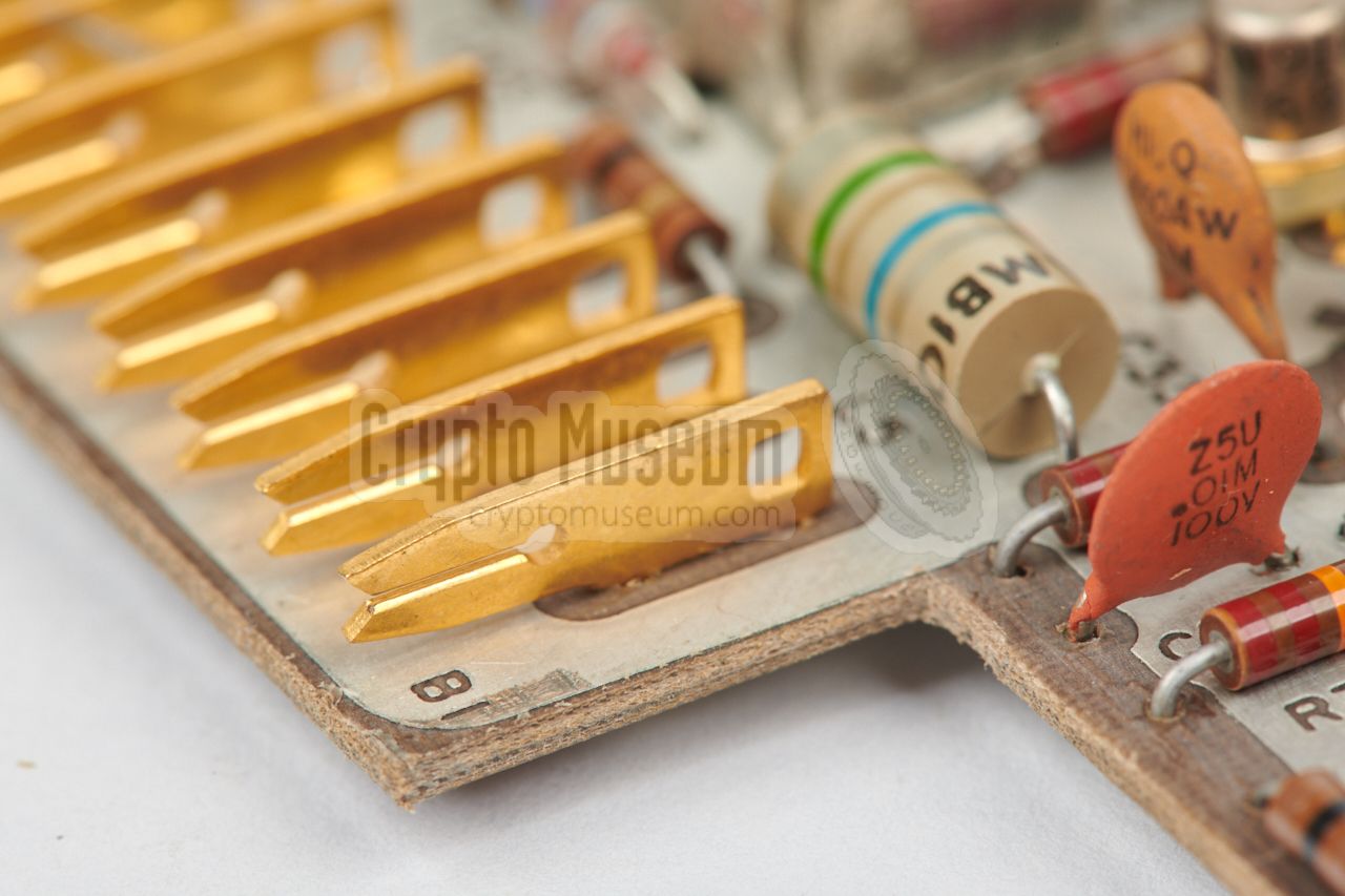
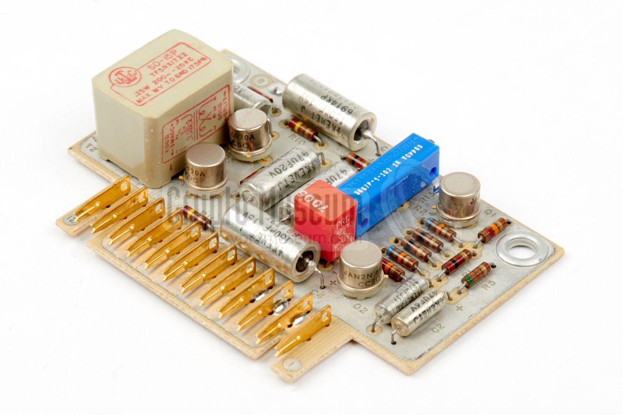
Considering its age, the SR-209 is extremely well built, using only first
class components and gold-plated contacts
where necessary. Most circuits are built with transistors from brands
like Motorola and
General Electric (GE),
but the AFC board holds a very early implementation of a
modular circuit block,
or integrated circuit (IC).
It is an operational amplifier (OpAmp), supplied by Zeltex
Inc. in Concord (California, USA)
and is visible in the image on the right as a large
black block at the centre. Inside this block, which was made by Philbrick,
is a potted hybrid circuit. 1
|
|
|
|
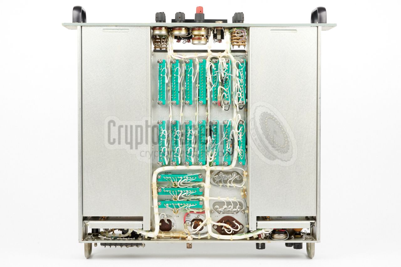
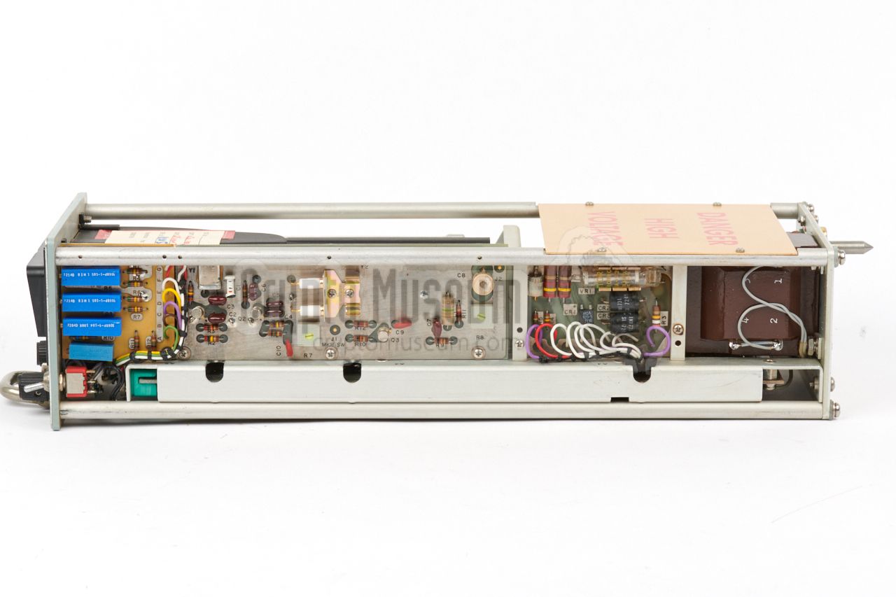
At the bottom of the mainframe
is the wiring between the sockets of the board, the AC mains transformer
and three large capacitors that are part of the power supply unit (PSU).
All wiring has teflon insulation, and shielded coaxial teflon wiring is
used for the RF, IF, video and audio signals.
|
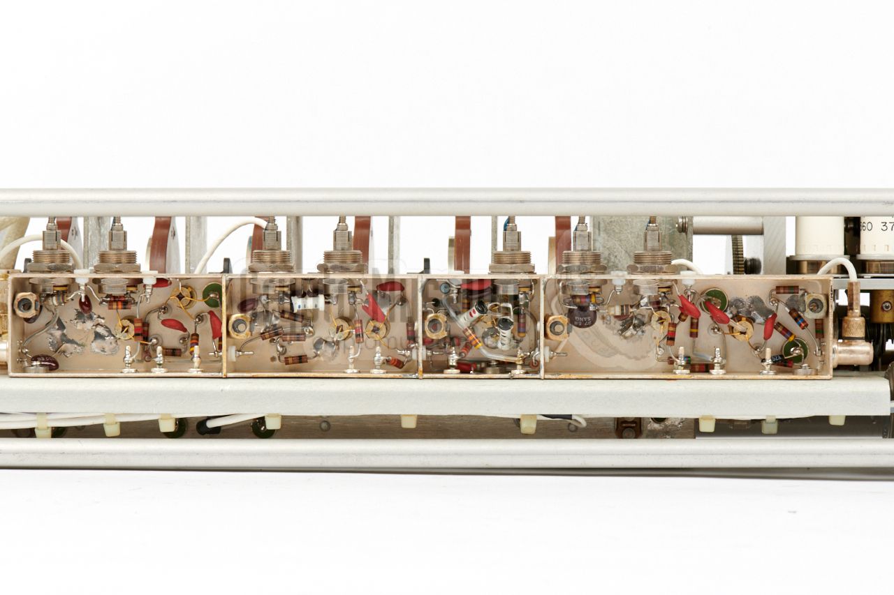
The mainframe has two expansion bays –
one at the left and one at the right –
that can take two types of plug-in units: a
tuning head (tuner) or a
Signal Display Unit (SDU, or panoramic display).
This means that a typical SR-209 receiver can hold two
tuners, or an SDU and a single tuner.
At least 15 different tuning heads were offered by ACL, each
with its own frequency range. In addition, at least four different
swept tuning heads
were available for electronic tuning and automated search. Depending on
the frequency, each tuning head was constructed differently.
|
|
|
|
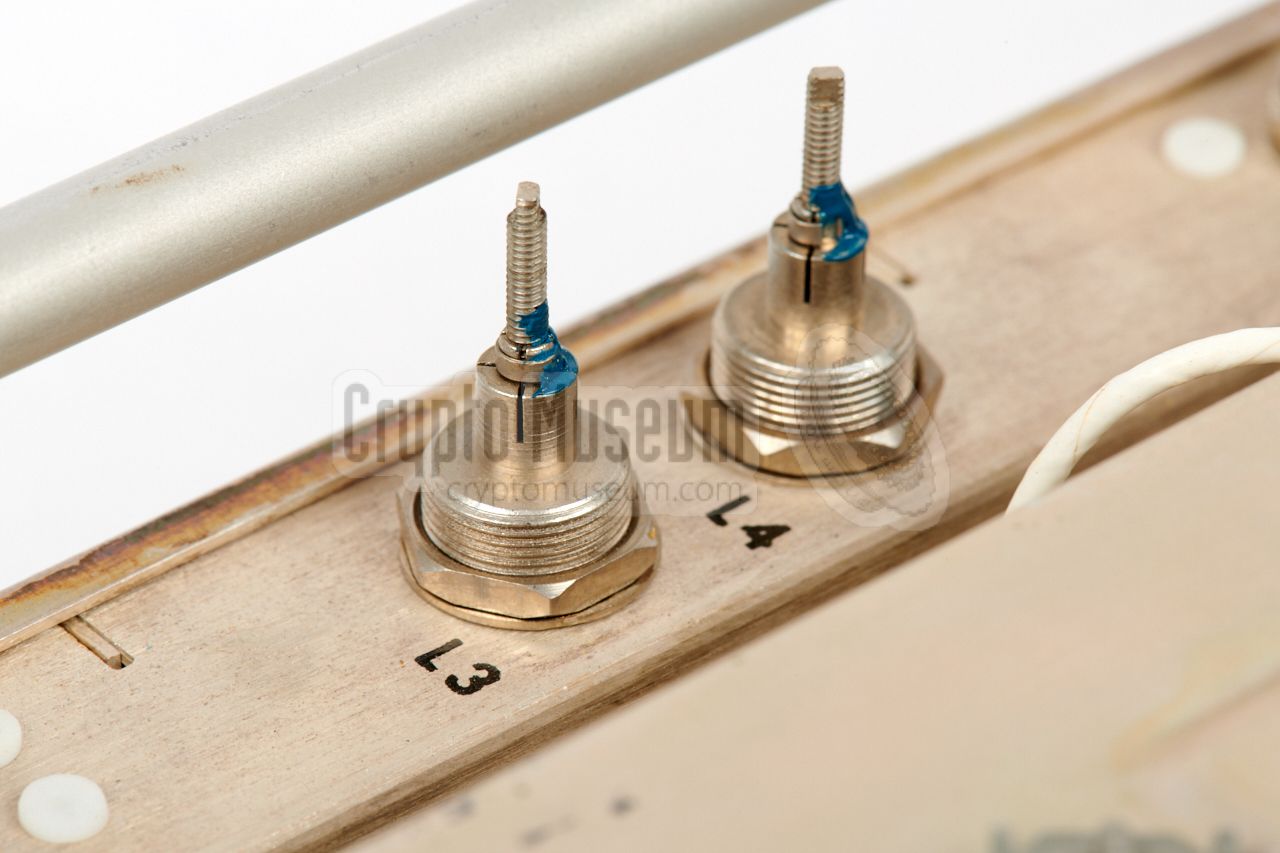
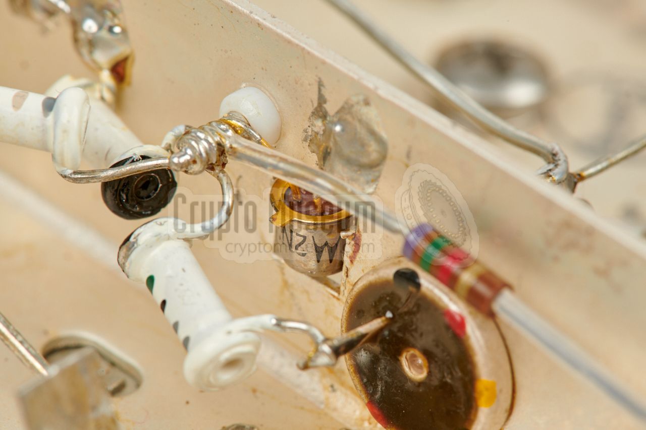
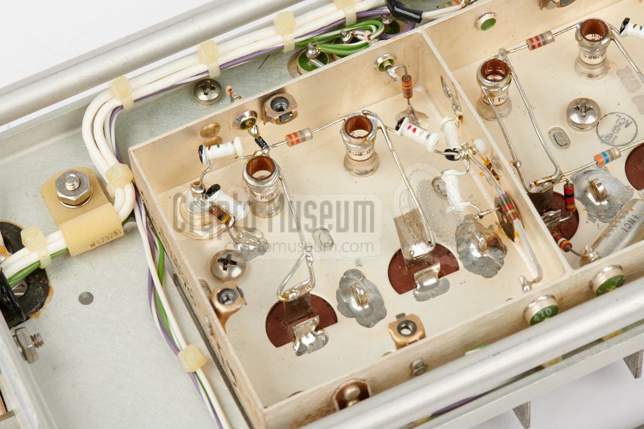
The image above shows the local oscillator of the
SH-203P tuner (250-500 MHz).
All HF tuning heads in the SH-100-series (2-45 MHz) produce an IF output
signal at 455 kHz, whilst all VHF, UHF and SHF tuning heads of the
SH-200-series (20-12000 MHz) produce an 21.4 MHz IF signal.
|
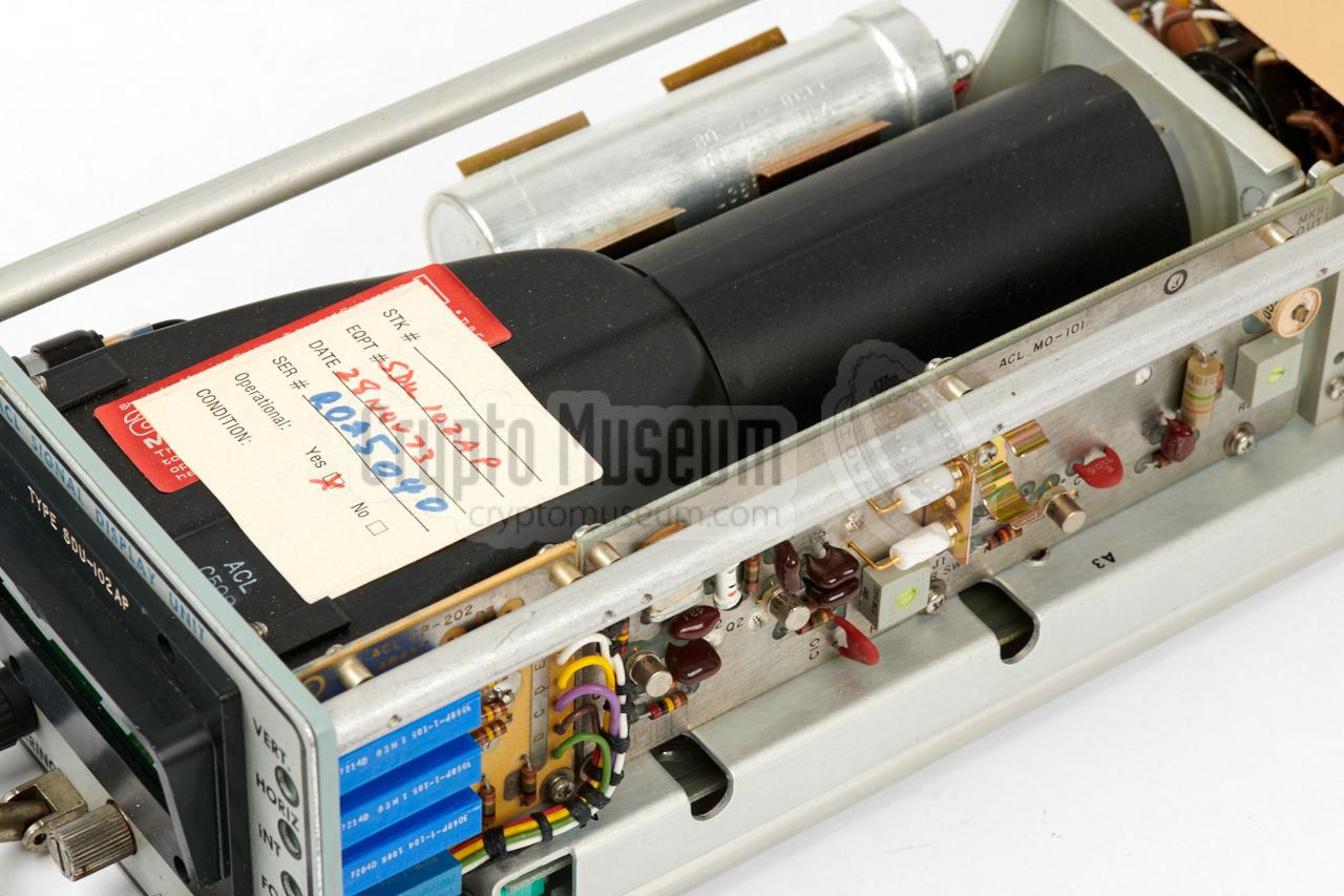
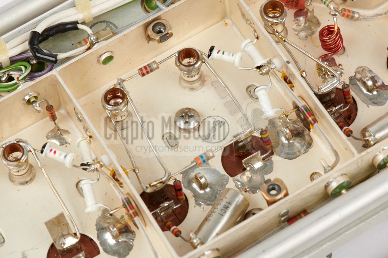
For this reason, there are two different SDUs: one for 455 kHz and one that
is suitable for 21.4 MHz signals. Inside the SDU is a narrow cathode ray
tube (CRT) with a green phosphor screen,
much like the ones that were present in old oscilloscopes.
The image on the right shows the CRT, plus one of
the driving circuit boards.
Behind the CRT (close to its connections) is the
HT-section with a transformer and a cascade
circuit. The remaining circuits are located at the
bottom of the unit.
The CRT can be adjusted with
four recessed multi-turn potentiometers.
|
|
|
|
The SDU-102AP allows part of the IF pass band – adjustable from DC to 3 MHz –
centred around 21.4 MHz, to be displayed on the CRT screen. A crystal-based
marker can be enabled, to help find the centre frequency on the screen.
In the same vein, the SDU-100P (needed with the 2-45 MHz HF tuners)
has a sweep width of 0-10 kHz or 0-50 kHz centred around 455 kHz [B].
|
-
The Zeltex ZEL-1 is listed in the service manual [C] as the
Philbrick PP65AU
[a]. It was probably supplied to Zeltex as an OEM part.
George A. Philbrick Researches (GAP/R) in Dedham (Massachusetts, USA) was
one of the pioneers of the Operational Amplifier [5].
|
The SR-209 featured on this page was manufactured by
ACL in August 1973, and has
previously been owned by the US
Central Intelligence Agency (CIA).
It was used throughout the 1970s and 1980s for testing
covert listening devices (bugs)
that operated in the UHF band around 380 MHz.
Once the receiver was decommissioned – some time after the transition
had been made to bugs operating at 1500 MHz – the receiver was put
on a shelf under humid conditions, where it stayed for the next 30
years, until it was donated to Crypto Museum. Although the exterior
had collected quite a bit of dust, the interior was surprisingly clean
and the components looked like they were made yesterday.
After reconditioning the electrolytic PSU capacitors,
the receiver was switched on and worked immediately. Even the frequency
calibration was still spot-on after all these years.
The following (minor) problems were observed:
|
- Mains cable brittle (unsafe)
- Meter glass broken
- Strong 50 Hz hum when COR (squelch) is active
- Power lamp broken
|
|
Fortunately, the original power cable (with the
exotic plug) was present,
but the rubber mantle had become brittle and showed signs of disintegration.
For safety reasons it was replaced by a modern neoprene power cable with
a suitable wall-socket plug for use in continental Europe.
|
The next thing to be fixed, was the transparent cover over the signal
strength meter, which had come off. As the meter is mounted very
close to the upper edge of the case, it is likely that it got damaged when
it was moved from one shelf to another. Luckily, the parts were still
present, and were easily glued back in place with Cyanolit™.
The problem of the 50 Hz hum was more serious and it took
a while to find its cause. Whenever the SR-209 was not receiving a
carrier, and the Carrier Operated Relay (COR)
– or squelch – fell off, a 50 Hz hum was heard in the headphones.
|
|
|
|
Strangely, the hum only started about 1 second after the COR relay had
turned off. Initially it was thought that it might be caused by a
faulty bridge rectifier in one of the power rails, but after checking
the DC power lines for any AC components (ripple),
this theory had to be discarded.
|
Next, the audio amplifier input was checked, and it was
observed that the hum appeared there as well – about 1 second after the
COR had turned off – although the supply to the audio pre-amplifier had
been fully cut-off at that stage.
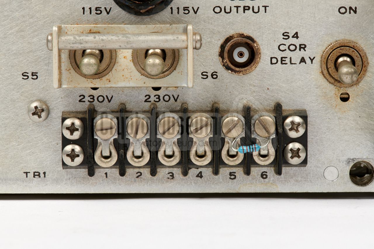
Long story short: it was caused by the 600Ω transformer at
the output of the power amplifier. Apparently, the open winding
for connection to an external amplifier, picked up hum from the mains
network and fed it back into the amplifier.
It was fixed by mounting a 1KΩ resistor accross contacts
5 and 6 of the TB1 terminal block.
|
|
|
|
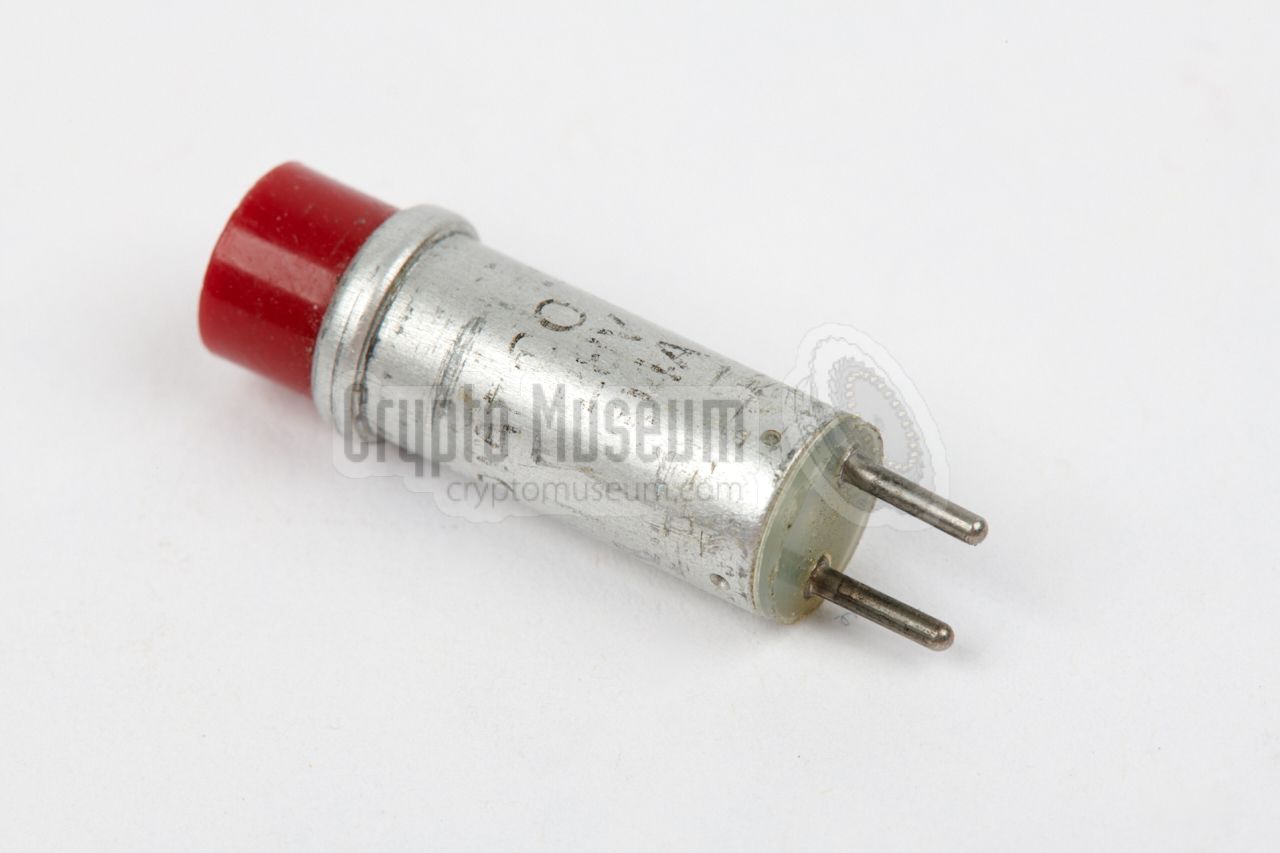
The last problem – the broken power lamp – was fixed more easily than
initially anticipated. It is shown in the image above and is in
fact a 28V filament lamp, mounted inside a pre-fabricated enclosure.
Luckily, these pilot lamps are still available from the original manufacturer
Dialight [b].
|
Device Surveillance receiver Purpose Surveillance and radio monitoring Model SR-209 Manufacturer Astro Communication Laboratory (ACL) Year 1965 Frequency 2 MHz -7 GHz (optionally to 12 GHz) Modulation AM, FM, CW, Pulse Impedance 50 Ω unbalanced Audio 100 mW into 600 Ω external speaker Video out 5V pp max. into 93Ω Video impedance 93Ω, BNC Display output 21.4 MHz Meters Tuning, Signal strength Power 115V AC (option: 230V AC), 50-400 Hz Dimensions 19" rackmount Weight 30 pounds
|
SR-209 First incarnation of the SR-209 receiver SR-209-6 Special version with large field strength indicator SR-209 C Last known incarnation of the SR-209 receiver
|
SH-102 P 2-6 MHz SH-103 P 6-20 MHz SH-104 P 20-45 MHz
SH-200 P 20-45 MHz SH-270 P 20-70 MHz SH-201 P 30-100 MHz SH-271 P 55-260 MHz SH-202 P 90-300 MHz SH-272 P 225-400 MHz SH-203 P 250-500 MHz SH-204 P 490-1000 MHz SH-205 P 990-2000 MHz SH-206 P 1990-4000 MHz SH-207 P-1 4-7 GHz SH-208 P-1 7-12 GHz
|
ESH-201 P A: 30-55 MHz B: 55-100 MHz ESH-202 P A: 100-190 MHz B: 190-300 MHz ESH-203 P 300-500 MHz ESH-204 P A: 500-740 MHz B: 740-1000 MHz
|
|
|
IF units for series 100 tuning heads
|
|
|
IF-112-01 1 kHz IF-112-05 5 kHz IF-112-10 10 kHz
|
|
|
IF units for series 200 tuning heads
|
|
|
IF-220-10 10 kHz IF-220-20 20 kHz IF-211-60 60 kHz IF-211-75 75 kHz IF-211-100 100 kHz IF-211-150 150 kHz IF-212-300 300 kHz IF-212-500 500 kHz IF-212-1000 1000 kHz IF-212-2000 2000 kHz IF-212-3000 3000 kHz IF-212-4000 4000 kHz IF-212-8000 8000 kHz
|
SDU-100P Signal Display Unit, for use with series 100 tuners→ spec SDU-102AP Signal Display Unit, for use with series 200 tuners→ spec FRO-201P Frequency readout plug-in 2—300 MHz FRO-203P Frequency readout plug-in 2—500 MHz ESH-200 Sweep (scan) option) FRO-201 External frequency readout unit BP-201P Rechargeable NiCd battery for mobile use
|
CRT size 1 x 3 inches (25 x 76 mm) Sweep width 0-10 kHz and 0-50 kHz (continuously adjustable) Resolution 400 Hz and 2 kHz Sweep rate 4 Hz Intermediate IF1: 80 kHz, IF2: 15 kHz Response ±1.5dB (amplitude response) Sensitivity 10µV @ 1" deflection Marker 455 kHz (crystal based) Linearity 5% Power ±12V DC (provided by SR-209)
|
CRT size 1 x 3 inches (25 x 76 mm) Sweep width DC to 3 MHz (continuously adjustable) Resolution 10 kHz Sweep rate 20 Hz Intermediate IF1: 4.3 MHz, IF2: 455 kHz Response ±1.5dB (amplitude response) Sensitivity 10µV @ 1" deflection Marker 21.4 MHz (crystal based) Linearity 5% Power ±12V DC (provided by SR-209)
|
|
Six contacts are available on a terminal block at the right side of the
rear panel. The first three contacts are operated by a relay inside
the COR (squelch) unit. The situation is shown when no carrier is
received. The 4th contact provides ground and the last two contacts
(5 and 6) provide a balanced 600Ω audio output, which can be
fed to an external amplifier or telephone line.
|
- COR relay normally open
- COR relay common
- COR relay normally closed
- Ground
- Audio out 600Ω (balanced) 1
- Audio out 600Ω (balanced) 1
|
|
-
Note that a 1KΩ resistor should be connected between points 5 and 6
when the output is unused, to avoid hum on the headphones output. The
resistor effectively loads the output transformer.
|
|
AFC
|
|
Automatic Frequency Control
|
|
AGC
|
|
Automatic Gain Control
|
|
BFO
|
|
Beat Frequency Oscillator
Optional oscillator that feeds a signal to the AM detector,
to make CW signals (morse) audible. Note that not all IF-strips
have a BFO.
|
|
COR
|
|
Carrier-Operated Relay
Noise cancelling when no signal is present. Also known as squelch.
|
|
LO
|
|
Local Oscillator
Generally speaking this is the first oscillator in a receiver that
directly controls the reception frequency. In this case, it is
a free-running variable frequency oscillator (VFO).
|
|
SDU
|
|
Signal Display Unit
Also known as spectrum display, or panoramic display.
|
|
VCO
|
|
Voltage Controlled Oscillator
Oscillator of which the output frequency is determined by a DC voltage.
|
|
VFO
|
|
Variable Frequency Oscillator
|
- ACL catalog
Date unknown. 1
- The SR-209 Receiving System, Brochure
June 1971. Retrieved from NASA CR-130232, January 1973.
- VHF/UHF Receiver Type SR-209, Manual
CM-303046. ACL, date unknown.
- Plug-in tuning head SH-203P-1/AFC (250-500 MHz), Manual
CM-303046. ACL, date unknown.
- IF Amplifiers IF-212-300, Manual
CM-303046. ACL, date unknown.
- IF Amplifiers IF-212-500, Manual
CM-303046. ACL, date unknown.
- SDU-102AP & SDU-103AP, Manual
ACL, date unknown. 1
|
-
Document kindly provided by Terry O'Laughlin [1].
|
|
|
|
Any links shown in red are currently unavailable.
If you like the information on this website, why not make a donation?
© Crypto Museum. Created: Tuesday 26 February 2019. Last changed: Monday, 24 March 2025 - 11:15 CET.
|
 |

|
|
|