|
|
|
|
|

|
|
Radar
Radar locator
MRP-4, codenamed Barbara, is a receiver for
direction finding of radar
stations, manufactured in the early 1970s by
Tesla
in Czechoslovakia.
It is suitable for the reception of pulse transmissions in the
1 - 10 GHz frequency range, and was used during the
Cold War
for identifying and locating (mobile) radar stations.
It can also be used for finding the location
of the illumination beam of an externally energized
covert listening device (radio bug).
Also known as NSN 5840-16-001-1378.
|
The receiver measures 24.5 x 18.5 x 60 cm and weight 3700 grams.
It is is constructed in such a way that it can be carried on the chest
with the two circular antennas facing forward and the control panel
at the top, visible to the operator.
The receiver can detect radio signals between 1 and 10 GHz
in its vicinity, and is suitable for the detection of pulse-modulated signals
(typically radar), navigation aids and other directional sources, such as point-to-point microwave radio links and bug activation beams.
It can also find the pulse repeat frequency of a radar signal.
|
|
|
The MRP-4 was first introduced in 1972 and was initially built mainly for the
Army of the Soviet Union (USSR).
It was also used on tanks and reconnaissance
vehicles in Czechoslovakia
and other countries of the Warsaw Pact.
It was so popular that it was kept in production until 1994. Note however,
that from 1989 onwards, Czechoslovakia was no longer part of the Warsaw Pact
and that technically the MRP-4 had become a West-European product,
complete with NSN number.
But even after Tesla
had ceased production of the MRP-4, it was used for many
years, probably because it offered good protection against hostile radio
signals and because it was relatively easy to operate.
According to the maintenance logbook that came with a Polish MRP-4,
that unit was re-issued for the Polish mission in Afganistan in 2012
after more than 10 years of storage [A].
In 1995, the MRP-4 was succeeded by the modernized MRP-4M,
with extended range to 18 GHz [B].
|
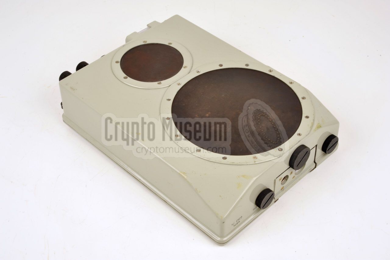
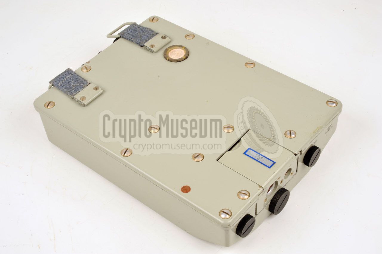
The MRP-4 is designed for operation from the operators chest. A canvas strap
should be attached to the two metal rings that are fitted to the unit's body
so that the device can be hung from the neck. The diagram below shows the front
side of the device that has two circular antennas: a large one for the lower
frequencies and a smaller one for the highest frequencies. All controls are
located at the narrow top panel,
so that they can be accessed easily by the operator.
The detector diodes for band I and IV are accessible from the
top panel. They are mounted in a special fitting.
The diodes for band II and III are located at the bottom side of the
device, as shown above. This image also shows the bay at the rear/bottom
for the NiCd battery
or the external power adapter. The unit is
shown here with the external power adapter installed. The installed part is held
in place by a black photo-thread bolt. The interior of the unit
can be accessed from the rear panel.
|
|
The MRP-4 had a range of options for powering the unit. It can be used as
a fully self-contained receiver with an internal NiCd battery that lasts
several hours, making it ideal for short covert surveillance operations.
Alternatively, it can be powered by an external battery pack that lasts
several days or even weeks. In addition, it can also be powered by an
external 9V DC source.
|
|
The internal NiCd battery pack (1) is fitted instead of the
external adapter (3). To ensure that it can be recharged under all
circumstances, various chargers are supplied with the set. Batteries
can be charged from the mains, a 12V car battery or another external source.
|
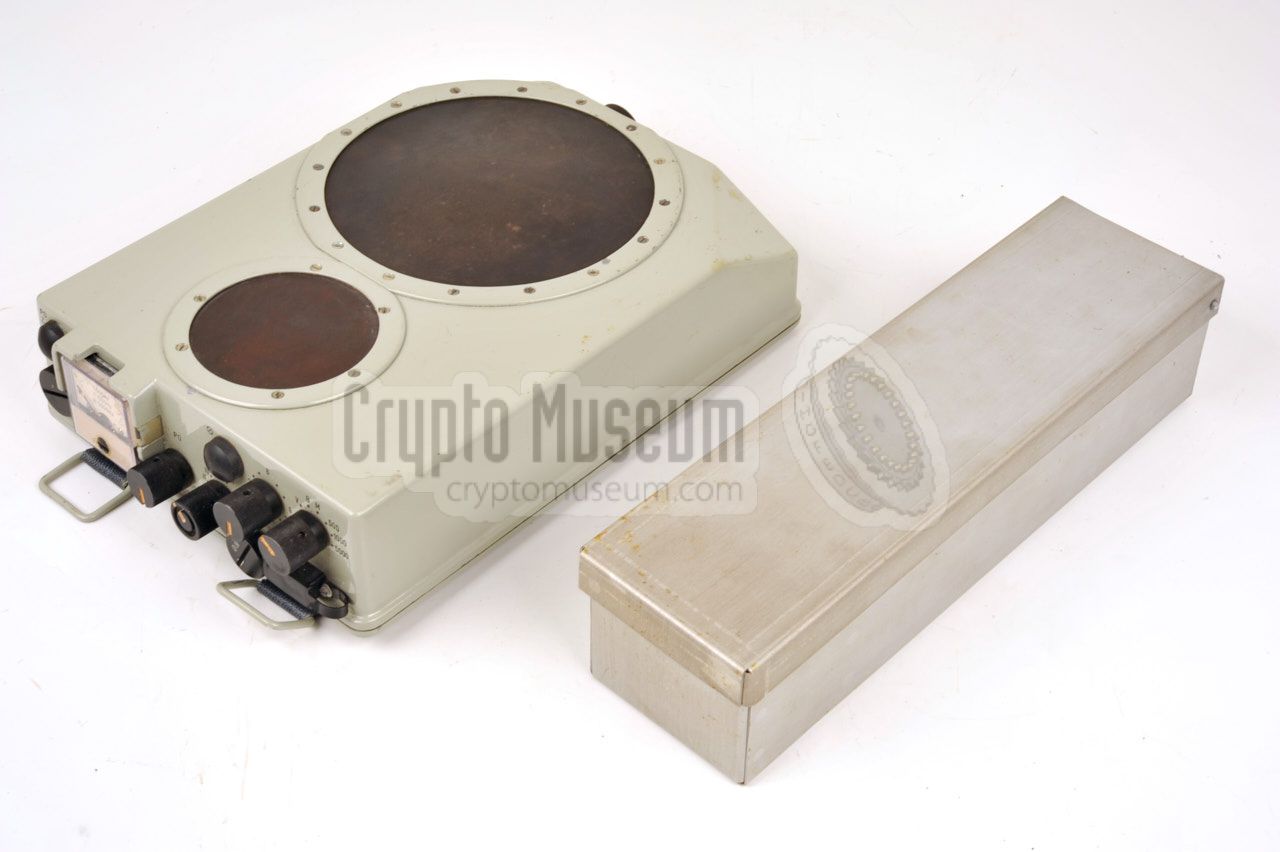
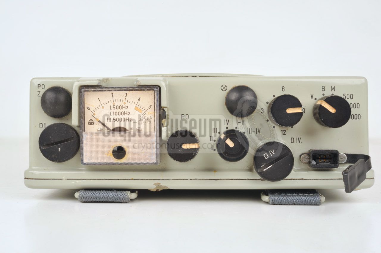
All controls of the MRP-4 are located at the front panel of the unit.
The receiver is constructed in such a way that, when it is carried on the
chest (using the neck belt), the controls are facing upwards, whilst the
antennas are at the front (facing forward). This gives the operator
easy access to the controls when using the receiver for direction finding
of an intercepted signal.
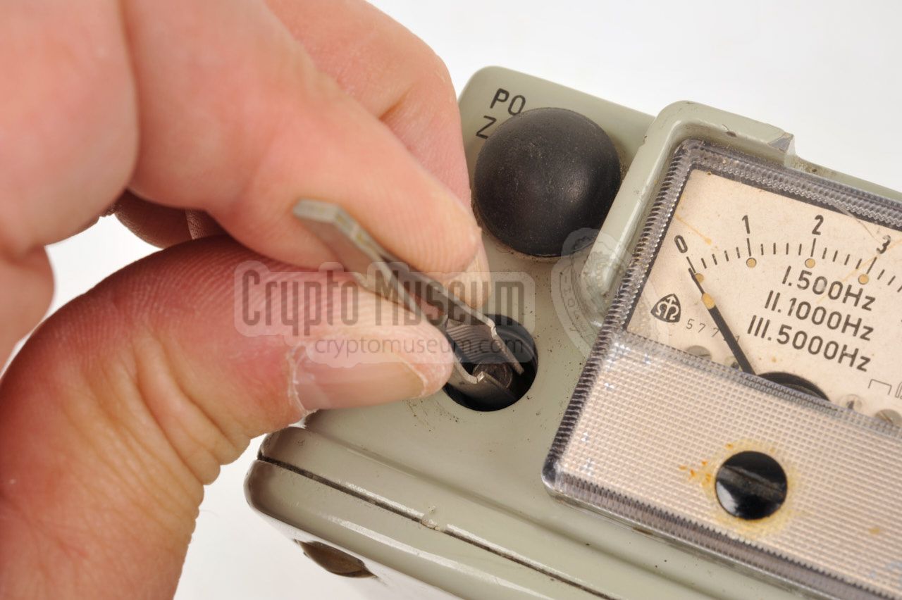
The unit is turned ON with the MODE selector at the top right.
The desired frequency band is selected with the RANGE selector,
whilst the sensitivity is adjusted with the Amplifier knob (between 1 and 12).
When operating the device in the dark, the scale illumination button can be
pressed to turn the scale lamp on temporarily. When receiving a radar signal,
its repeat frequency can be determined by pressing the PO Z button at
the top left and rotating the PO knob until the tone frequency is the same.
The correct frequency can than be read from the meter scale. Note that for
this feature, the MODE selector has to be set to a suitable range:
500, 1000 or 5000 Hz.
|
V Off B Battery check M Impulse count 1 500 500 Hz repeat frequency range 1000 1000 Hz repeat frequency range 5000 5000 Hz repeat frequency range
|
-
In this mode (M) the device counts the impulses in the direction of the
antenna. The count is shown on the meter and can be cleared with the PO Z button.
|
|
The MRP-4 supports a frequency range from 1 to 10 GHz, divided over 4 bands,
marked I, II, III and IV. Note that band I is for the highest frequency band
`and band IV is the lowest.
Within a band, the receiver is aperiodic, which
means that it does not have to be tuned. As a result, the MRP-4 can only
be used in close proximity of a transmitter.
The bands are divided as follows:
|
- 7,000 - 10,000 MHz
- 3,300 - 7,000 MHz
- 1,900 - 3,200 MHz
- 1,000 - 1,800 MHz
|
|
During the Cold War,
the MRP-4 was used in many countries of the
Warsaw Pact
and also in the former Soviet Union (USSR).
In the Czechoslovak
People's Army (ČSLA) it was issued as part of
the standard gear inside the BPzV Svatava 1 reconnaissance vehicle, where
it was used for detecting and finding enemy (mobile) radar installations [4].
In the Hungarian Army the MRP-4 was used on pre-strike and post-strike
surveillance missions behind enemy lines, by the highly trained and well-equipped
Special Reconnaissance Force (SRF), for locating radar sites
and C2 2 nodes [5].
|
In the event of a war between East and West, the MRP-4 would have been used
to locate fixed ground radar installations and categorize them. It would also
have been very effective against the mobile pulse-doppler radar systems
used by the Western reconnaissance units, like the Marconi 3
ZB-298 4 shown in the
image on the right [6].
The ZB-298
was a static (i.e. non-rotating) pulse doppler radar that worked
at ~10 GHz and gave an audible feedback of a moving object. A
well-trained operator could recognise the sounds and identify
moving men, vehicles, tracks, tanks, etc.
|
|
|
The ZB-298
also had a visual indicator, constructed from a red laser and a
rotating mirror, that allowed distance and size of the moving object to be
measured accurately. The image above was probably taken in The Netherlands,
as the antenna is labelled PAS OP (watch out).
The MRP-4 would have been able to effectively detect, identify and
locate this enemy reconnaissance unit.
➤ More about the ZB-298 radar
|
-
The BPzV Svatava vehicle was based on the Czechoslovak BVP-1K, which in
turn was a copy of the Russian BMP-1 reconnaissance track vehicle.
-
C2 = Command and Control.
-
Marconi-Elliot Avionic Systems Ltd, a GEC Marconi Electronics company.
-
The ZB-298 was known in the UK as Radar GS No. 14.
|
|
The MRP-4 was even used in Afganistan as part of the Polish Military Contingent,
as late as 2012. Although it is not entirely clear for what purpose it was
deployed in Afganistan, it is likely that it was used to detect and locate
SHF 1 radio links or mobile (GSM) phones used by the Taliban.
For this purpose, old MRP-4 units, that had been in storage for more than 10 years,
were re-issued. 2
|
-
SHF = Super High Frequency.
-
See deployment status of Polish MRP-4 [A p14].
|
|
Although this hasn't been confirmed, the MRP-4 would have been ideally
suited for finding the source of a
passive covert listening device,
such as The Thing,
SATYR
or Easy Chair.
Bugs of this type are usually activated and powered remotely by
a very strong narrow microwave beam that is aimed at the device
from a nearby position, typically a few hundred metres from the target.
|
Although suitable microwave detectors were available from the USSR, such
as the Osobnjak 8,
such detectors could not be used to trace and
locate the source of the activation beam.
The antennas of the MRP-4 however, have a very narrow opening angle of
1° - 2°, making it very easy to follow the beam. It could be worn
inconspicuously
under the operator's clothing, using just a small earpiece for the acoustic
indicator.
➤ More about bugs
|
|
|
|
The use of the MRP-4 by the following countries has been confirmed:
|
- Czechoslovakia
- Hungary
- Poland
- Soviet Union (USSR)
|
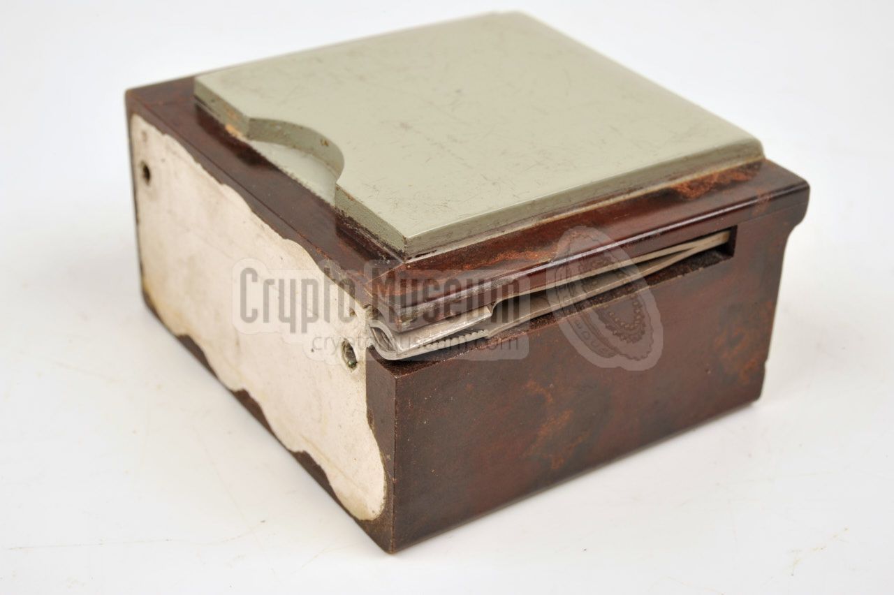
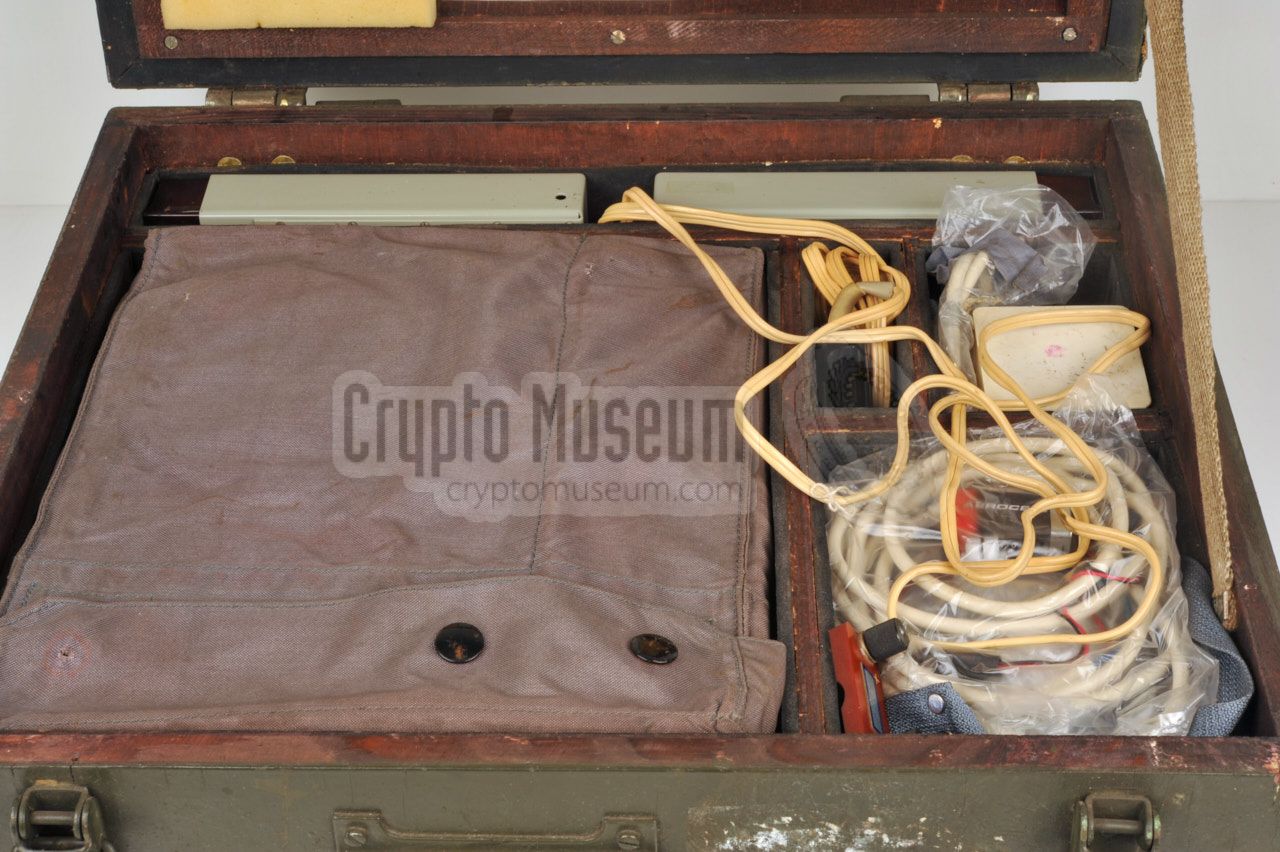
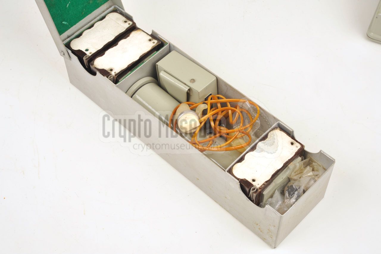
The MRP-4 was usually supplied in a wooden transit case, complete
with a range of spares, supplies, accessories and documentation.
The case has four padded compartments
in which the various parts are protected during transit.
Inside the top lid of the case is a checklist
and a storage plan,
so that the user can identify any missing parts and order them if
necessary.
|
|
|
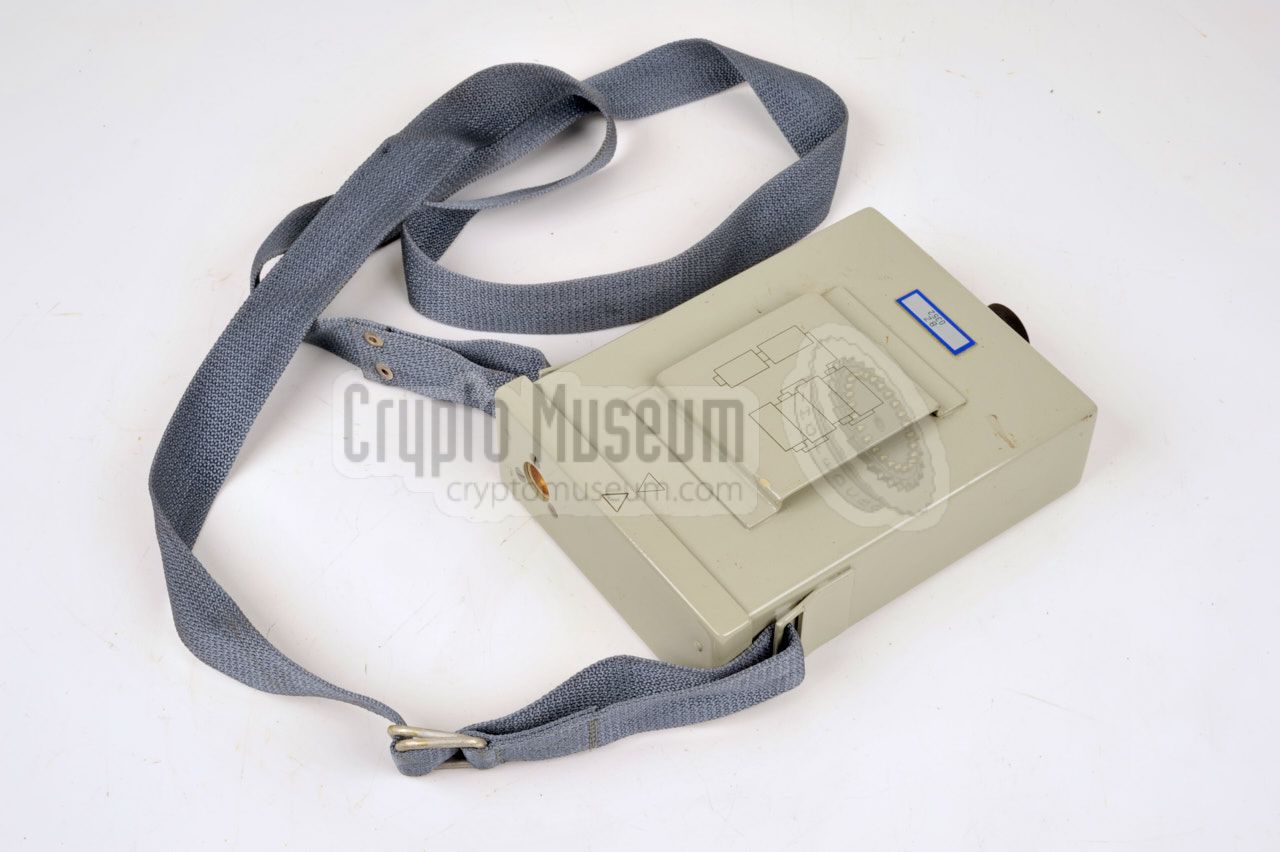
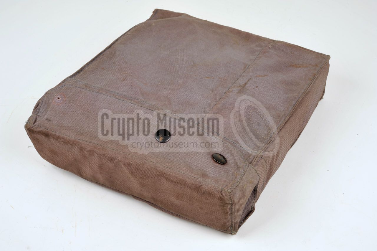
A canvas water-resistant carrying bag with a matching neck belt was supplied
with the set. It allows the receiver to be carried on the chest under harsh
conditions, such as rain.
The carrying bag is shown in the image on the right and has space for the
receiver and the accessory box. The receiver can be operated from within
the carrying bag.
|
|
|
The MRP-4 has two indicators for providing feedback about the intercepted
(radar) signal: optical, via the meter at the front panel, and acoustically,
via the earphones.
The earphone is connected to the small rectangular socket at the bottom
right of the front panel.
Spare earphones and L/R earbuds are supplied with the set.
|
|
|
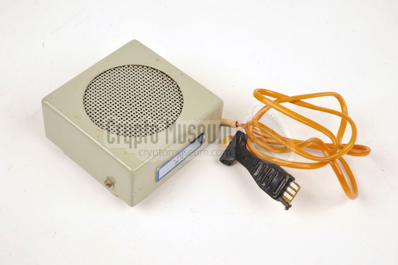
For training purposes, the earphones can be replaced by a speaker,
so that more people can hear the acoustic indicator. A small suitable
speaker is supplied with the set and is normally stored inside the accessory
box.
The speaker was not recommended for covert and surveillance operations, as
it would give the position of the interceptor away.
|
|
|
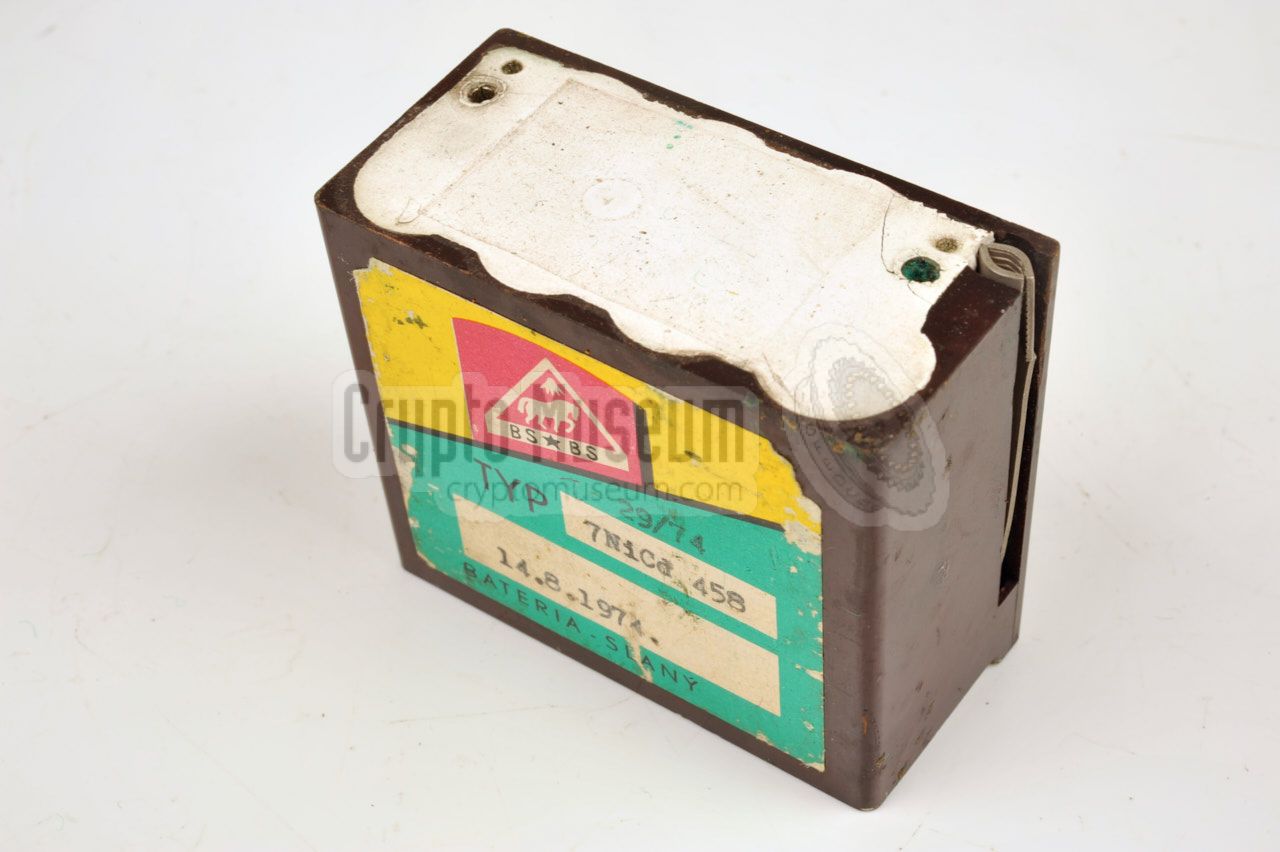
The radio is normally powered by an internal 8.4V / 450 mAh NiCd battery
that is installed at the back of the unit. As the receiver consumes
approx. 20 mA, a full battery should last for about 12 hours at normal
temperatures. The battery voltage can be checked with the meter.
Each battery also holds a pair of tweezers.
To allow uninterrupted operation, one or more spare NiCd batteries were
supplied with the set. Alternatively, the MRP-4 can be powered by an
external power pack (also supplied) or any other 9V DC source.
|
|
|
|
|
Mains AC battery charger
SN
|
|
|
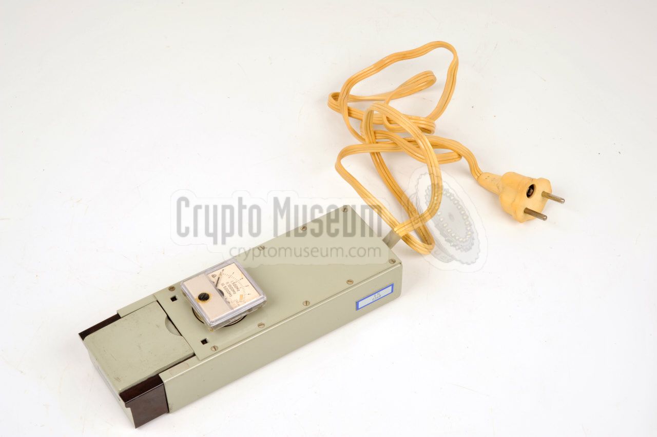
The internal battery is normally recharged with the AC battery charger
shown on the right. It is supplied with the set and allows the NiCd battery
to be charged from the 220V AC mains.
The meter can be installed to monitor the charging voltage. This is the same
(removable) meter as is used on the receiver's front panel.
|
|
|
|
|
Mobile DC battery charger
PN
|
|
|
When using the MRP-4 in a mobile environment, it is also possible to recharge
the batteries from a 12V DC car battery. A suitable mobile charger is supplied
with the set. It can be connected to the cigarette lighter socket of the car.
The mobile charger has the same physical shape as the mains charger, as shown
in the image on the right. Both chargers share the same meter. Note that the
AC and DC chargers were sometimes combined into a single unit (see below).
|
|
|
|
|
Universal AC/DC battery charger
UN
|
|
|
With some MRP-4 units, the two battery chargers shown above (AC and DC)
were replaced by a single one, named 'UN', shown on the right.
It has two
power cords: one for connection to the AC mains and one for connection
to a 24V DC source, such as the battery of a truck. If the UN unit was
present, the SN and PN chargers were omitted. The UN charger was stored
in the wooden transit case in the space that was normally taken
by the other two chargers.
|
|
|
|
|
Battery terminal block
PP
|
|
|
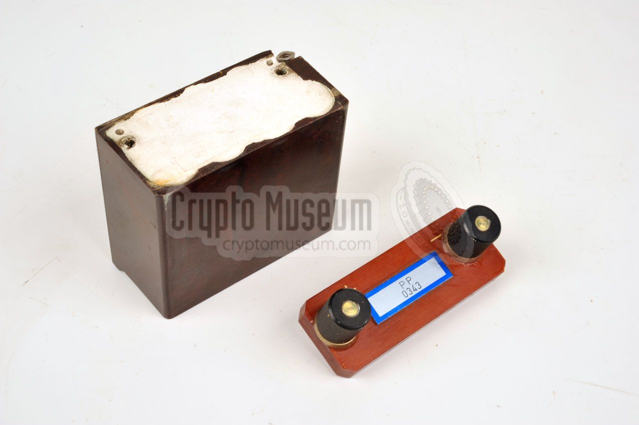
If the existing methods for recharging the batteries are not available,
for example when the DC charger is broken, they can also be charged by
means of an improvised method.
In order to get access to the recessed contacts of the batteries, a brown
pertinax terminal block is supplied. It can be installed on top of the
battery and makes the (+) and (-) contacts available on two regular terminals.
|
|
|
|
|
External power adapter
PS
|
|
|
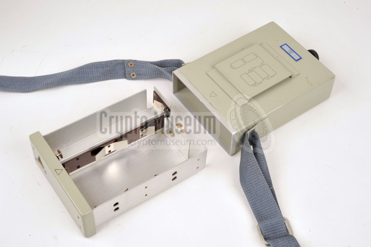
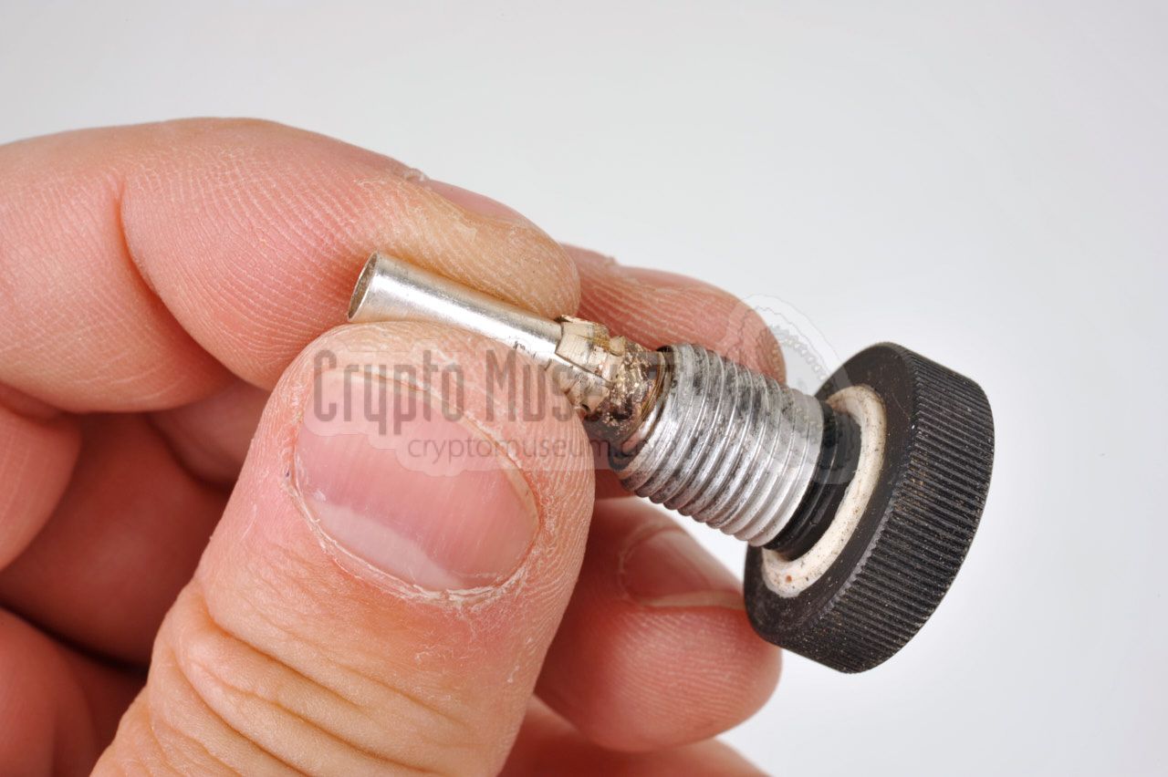
When using the MRP-4 in combination with an alternative power source (anything
else than the internal NiCd battery), the external power adapter has to be
fitted. This adapter is installed instead of the normal NiCd battery and has
two connections: a 5-pin DIN socket and a coaxial socket. The latter is used
for connection of the portable power pack or any other 9V DC source.
The adapter is held in place with a black tripod screw. The image on the right
shows the adapter aside the battery bay.
|
|
|
If the MRP-4 has to be used continuously for an extended period of time
(i.e. several days or even weeks), the external power pack should be used
instead of the small internal NiCd batteries.
The power pack takes 6 large 1.5V D-type batteries and can be carried around
the neck using a supplied strap. Alternatively, it can be attached to a
belt.
|
|
|
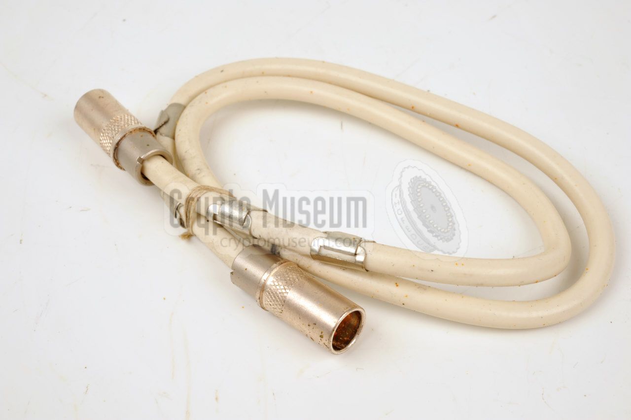
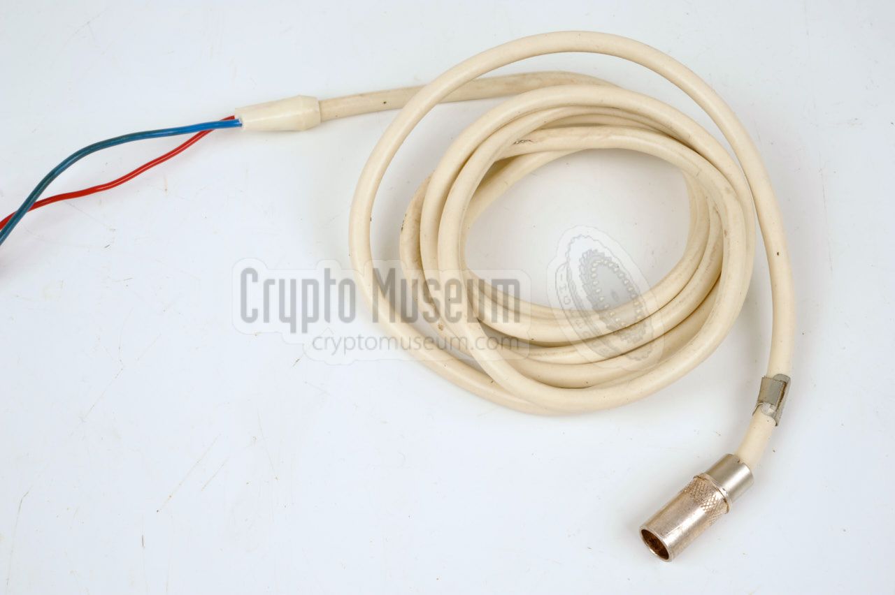
A short power lead is supplied for connection of the external power pack
to the receiver. It is a short piece of coaxial cable with two silver-plated
coaxial plugs at the ends.
When using the external power pack, the internal battery should be replaced
by the external power adapter.
The cable is used to connect the external power pack to the coaxial socket
on the adapter.
|
|
|
A separate cable is supplied to allow the MRP-4 to be powered from another
(external) DC power source. This can be useful if all other methods are
unavailable, if the batteries are flat, or when the receiver is used in a fixed
setup such as a static or mobile monitoring station.
It allows the MRP-4 to be powered by an alternative 9V DC power source,
such as a battery or a mains power supply unit (PSU).
|
|
|
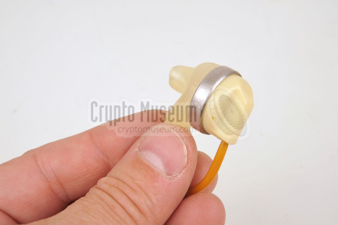
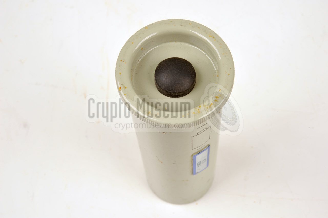
The small cylincdrical unit shown in the image on the right was supplied
with each MRP-4 to test its functions. The device contains a small
electromagnetic relay that is powered by a single 1.5V D-type battery.
The device produces enough static noise from switching its contacts,
that it can be heard on any of the four frequency bands. In practice it
was used to check whether the detector diode for each band was still
functioning properly.
|
|
|
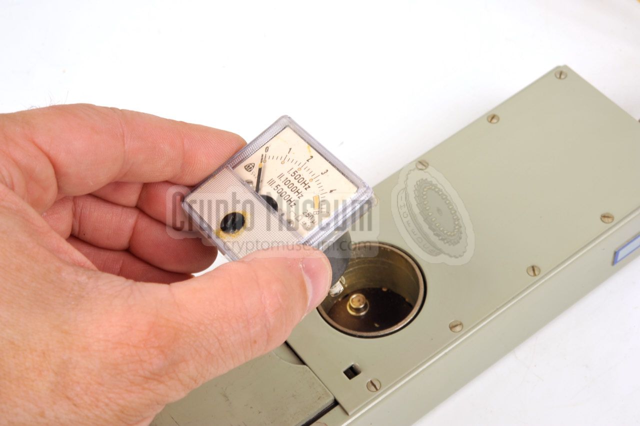
The meter is a special, versatile and fragile instrument. It is used as
a signal indicator on the body of the receiver. The same meter is also used
for checking the voltage when charging the batteries. As the same meter is
used in three places, it has been constructed as a plug-in unit.
The meter can be pulled out of the receiver's front panel and can be installed
in one of the chargers. As the meter is a fragile instrument, a spare one is
supplied in the accessory kit. It is usually store inside a small plastic
container.
|
|
|
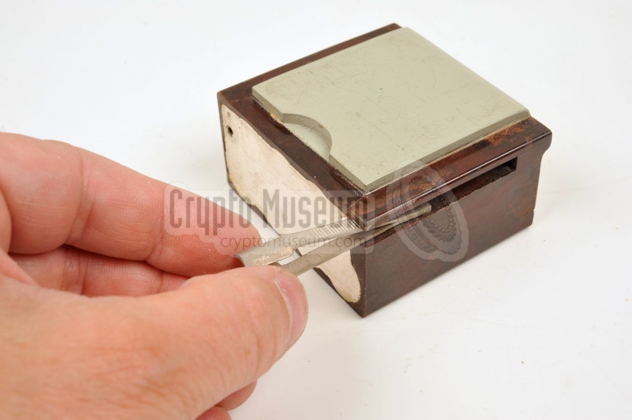
When replacing a broken detector diode, there is a chance that after
taking out the black fitting, the diode is left behind inside the socket.
For this reason a pair of tweezers is supplied with every NiCd battery.
In fact the tweezers are stored inside the side of the NiCd battery.
The tweezers are short and are shaped in such a way that a diode can be held
without damaging it. Replacing a diode is further described below.
|
|
|
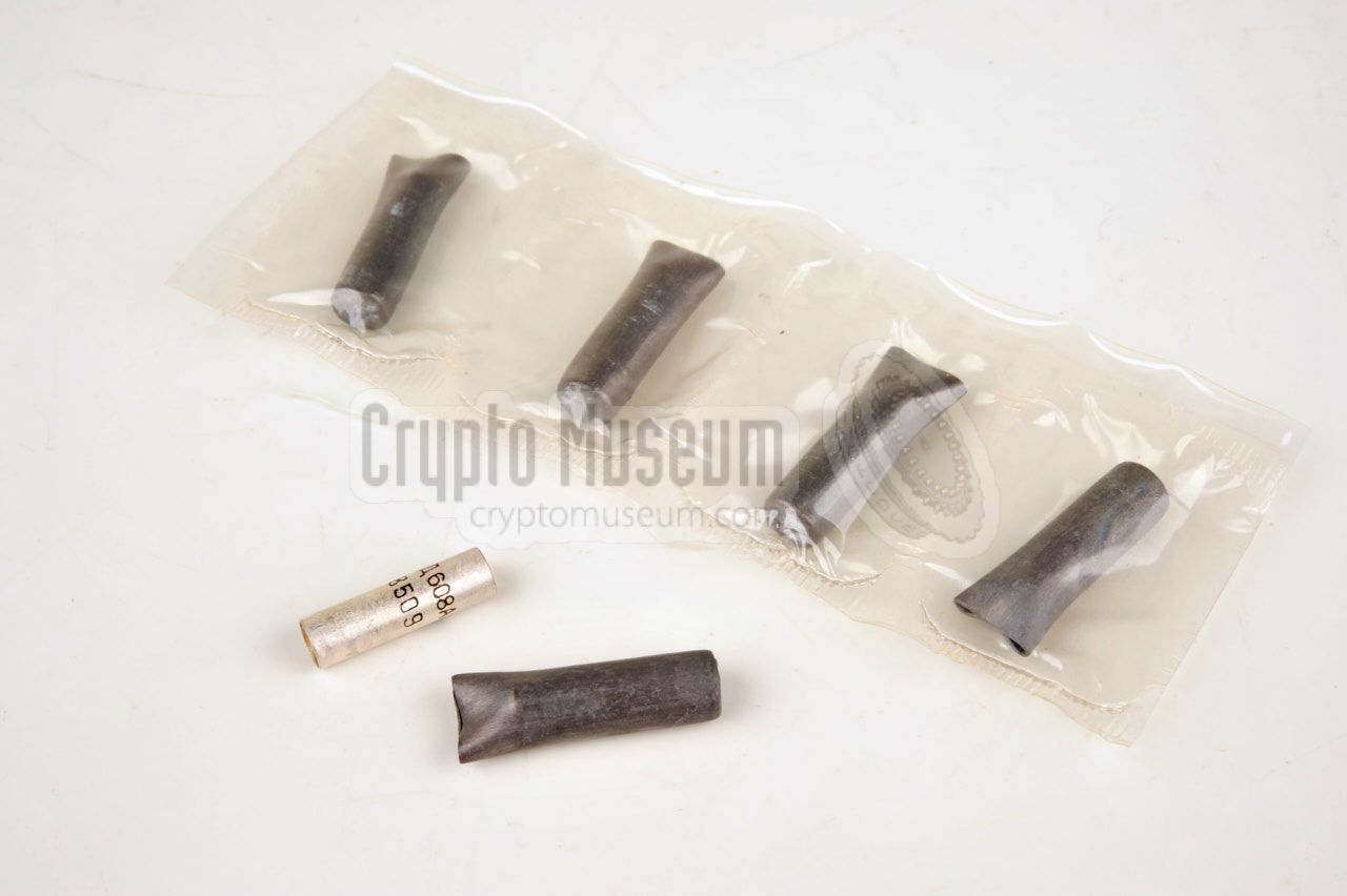
At the heart of the MRP-4, a set of four detector diodes are used.
As these devices are sensitive to static discharge and EMP, four spare
D608A diodes were supplied with each kit.
The diodes were usually supplied in a plastic sealed bag as shown in the
image on the right. Each diode is individually packed inside a lead cover
to protect it against static discharge and EMP whilst in transit.
➤ More about the diodes
|
|
|
In most cases, the MRP-4 came with some kind of logbook that holds the
release date, parts list, issuing status and repair/maintenance record.
The booklet shown on the right, was issued with an MRP-4 that was used
in Poland. It reveals that the unit was manufactured in 1974 and that
it was used until 2012.
We do not show the contents of this booklet as it contains names and
signatures of actively serving Polish military personnel (2016).
|
|
|
|
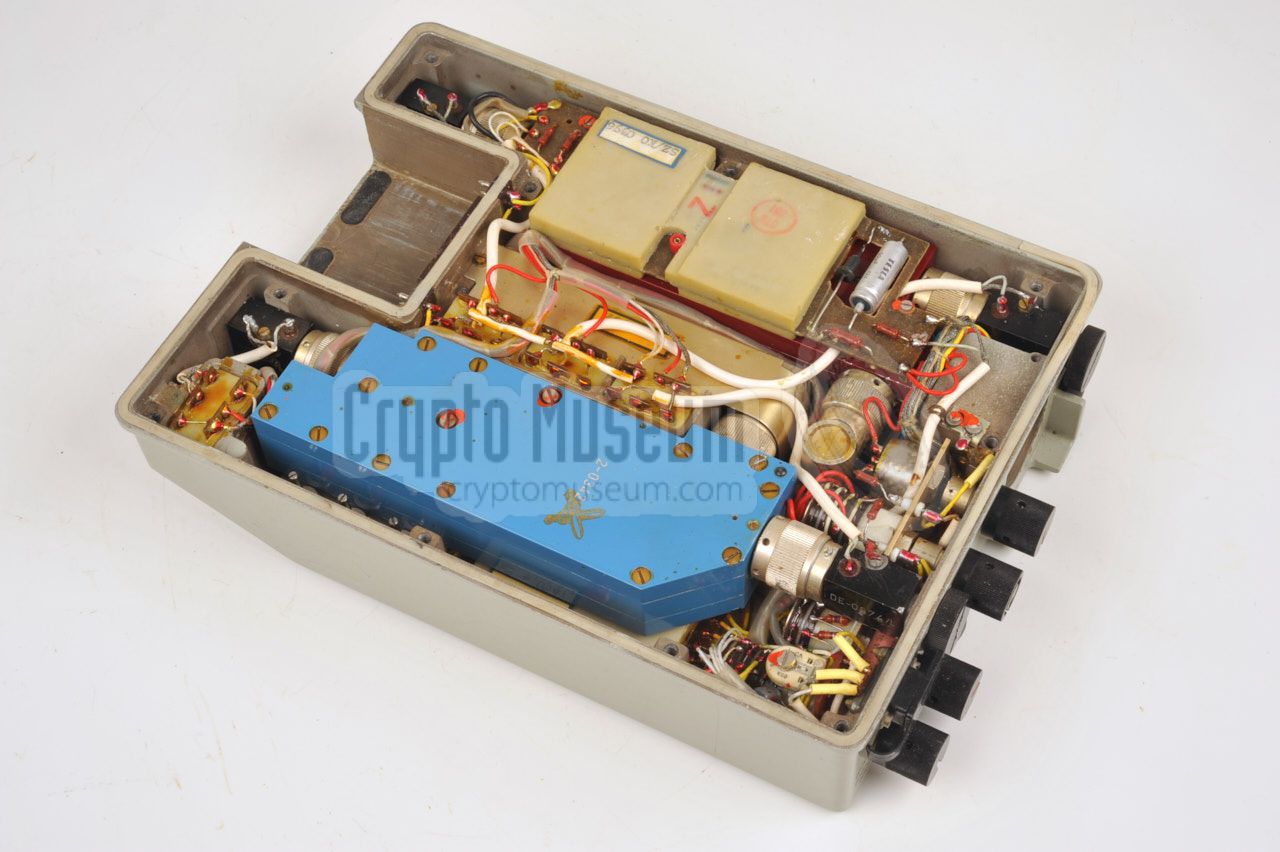
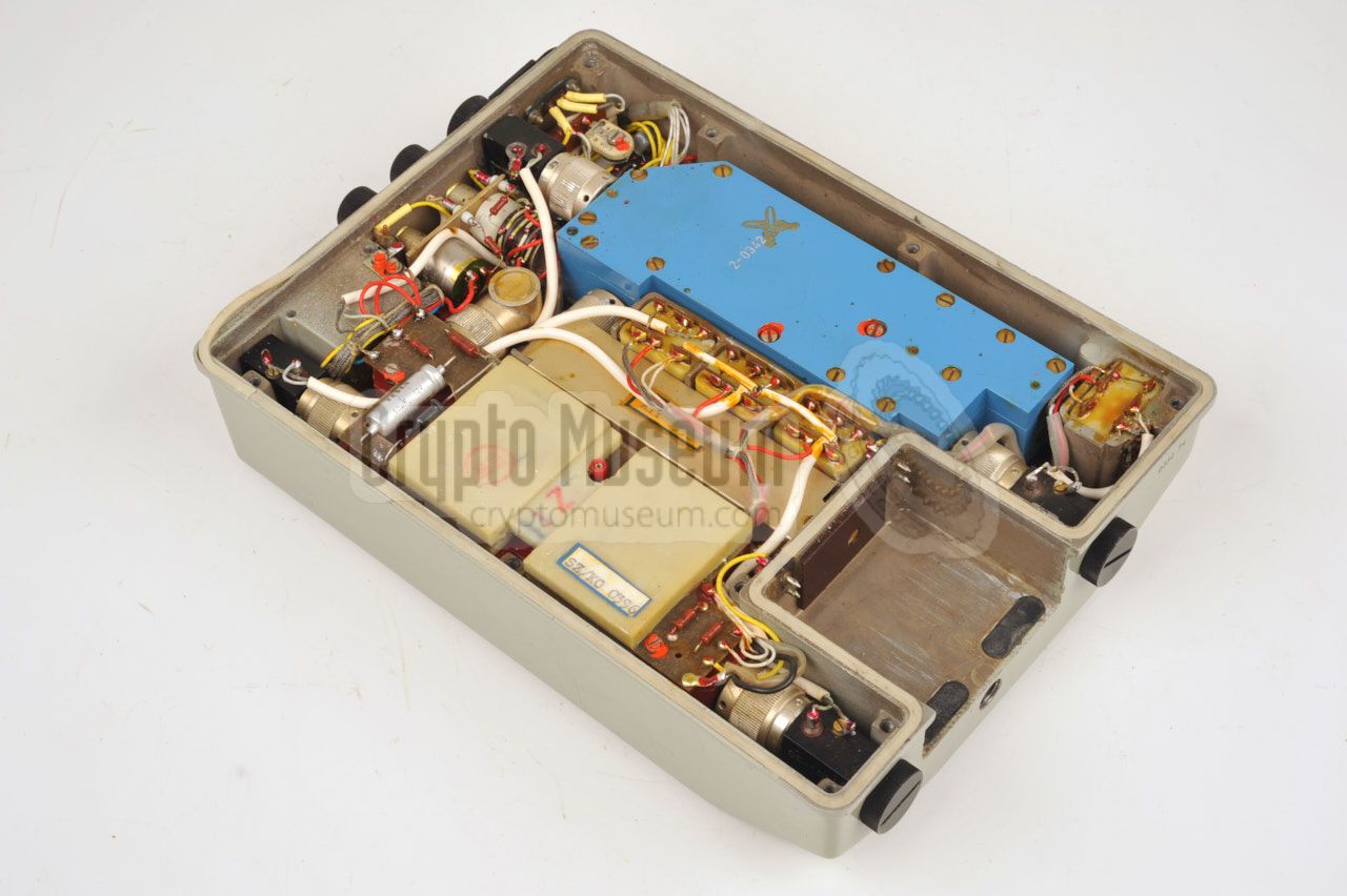
Despite its simple function, the MRP-4 is a complex device with
many rigid Super High Frequency (SHF) parts mounted in a rather small space.
The parts are housed inside a heavy die-cast metal enclosure and can be
accessed from the rear side of the unit, by removing the rear panel.
|
|
This is done by removing 13 large bolts from the
rear panel
after which it can be taken off. Note that one recessed bolt
may be sealed with a wax seal and that another
one covers a test point.
The image on the right shows the interior of the MRP-4 after the rear
panel has been removed.
|
|
|
Although we do not have access to the technical description of the MRP-4,
we can make a few educated guesses after studying the interior.
The device has two antennas: a small one for the highest frequencies
(bands I and II) and a larger one for the lower frequencies (band III and IV).
Each band has it own D608A detector diode,
as shown in the simplified block diagram below.
After selecting the desired band, the detected signal is amplified and
sent to the earphones or speaker. The signal is also shown on the visual
indicator (meter). Note that the actual band selector is more complex, as
it also allows band I and II to be monitored simultaneously. The same
is true for bands III and IV. The adjustable tone generator is not shown here.
|
|
One of the most critical parts of the MRP-4 is the Russian detector diode
D608A (Д608А). It is extremely sensitive to static discharge and spare
ones were usually supplied with each kit.
After 1994, even this Russian diode was given an
NSN number: 5840-99-972-1922. It is still available today from Russian
sellers on eBay. Note that the fitting for the Band IV diode has left-handed
thread, which is why a spare Fitting IV was supplied.
Turning it counter-clockwise tightens it!
|
- D608A
- D608A
- D608A
- D608A ← counter clockwise thread
|
|
|
When a broken diode has to be replaced, open its fitting by rotating its
black cap counter clockwise (or clockwise if you are replacing the band IV
diode).
If all goes well, the diode will be clamped in between the silver-plated
contacts of the cap, and will come out with the cap.
|
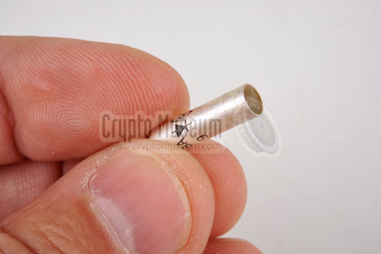
Also, ensure that the open end of the diode (with the tiny little contact
tip at the centre) is visible.
Next, carefully re-install the cap and ensure that the diode goes in
smoothly. If it binds, remove it and try again. Never use excessive force.
With the diode all the way in,
screw the cap in tightly.
|
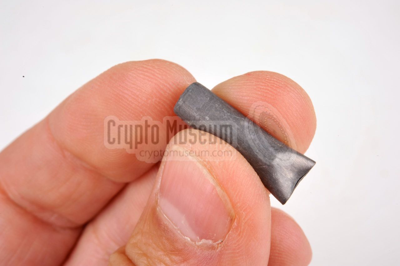
A pack of four spare D608A diodes
was supplied with each kit, commonly sealed
in plastic. To protect the diodes against static discharge and strong EMP, 1
for example after a nuclear blast, each diode was
individually covered in lead.
The image on the right shows a typical D608A diode as it was commonly
supplied. The lead cover has been partly peeled off to reveal the diode inside.
The diode can now be removed from its protective cover, but one has to be
careful not to touch the contact tip at the other end. Always
hold the diode
at the closed end.
|
|
|
When replacing a diode, ensure that the closed end is
fitted inside the cap
and the contact tip is facing outwards, as
shown here.
When repairing a broken MRP-4 unit, spare D608A diodes can usually
be found on auction sites such, as eBay as New Old Stock (NOS) items (2016).
|
 |
|
-
With some MRP-4 units, items 15 and 16 were replaced by a single universal
charger, marked 'UN'.
|
The storage plan below shows where the various items are stored inside
the transit case and the accessory box. This storage plan is usually present
inside the top lid of the transit case.
|
Device Radio direction finder Purpose Detection, identification and locating of radar signals Model MRP-4 Manufacturer Tesla Country Czechslovakia Year 1972 ~ Principle Direct conversion, with RF filters, video detectors and video amplifiers Frequency 1 - 10 GHz, 2.7 to 32 cm, divided over 4 user-selectable sub bands Indication Optical (meter), acoustic (speaker or earphone) Method Direct or Differential Power 8.4 V DC Current 20 mA Uptime 12 hours (with internal NiCd battery) Size 24.5 x 18.5 x 60 cm Weight 3700 g
|
We are still looking for the operating manual for the MRP-4 and/or any
document that was originally supplied with the device. If you have any
of these available, or if you know how to operate this unit, please
contact us.
|
-
This booklet is held in the collection of Crypto Museum, but is not available
for download as it contains names and signatures of actively serving military
personnel (2016).
-
Manual kindly provided by ZKRAT (www.zkrat.com).
|
|
|
|
Any links shown in red are currently unavailable.
If you like the information on this website, why not make a donation?
© Crypto Museum. Created: Tuesday 26 July 2016. Last changed: Monday, 18 May 2026 - 07:51 CET.
|
|

|
|
|
|


![Marconi ZB-2987 mobile static doppler radar. Retrieved from [6]. Source unknown.](../../radar/zb298/img/zb298_small.jpg)